$42.95
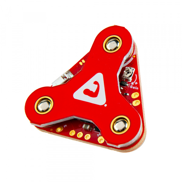
Using our muscles to control things is the way that most of us are accustomed to doing it. We push buttons, pull levers, move joysticks... but what if we could take the buttons, levers and joysticks out of the equation and control it with our muscles? The MyoWare 2.0 Muscle Sensor is an Arduino-compatible, all-in-one electromyography (EMG) sensor from Advancer Technologies that allows you to do just that! The MyoWare 2.0 Muscle Sensor has been redesigned from the ground up with a new, easy-to-use, compact design and upgraded with the latest and greatest chipset improving sensor performance and reliability. The innovative snap connector system eliminates the need to solder connections for the MyoWare 2.0 ecosystem. It's that easy: stick on a few electrodes (not included), read the output voltage and flex some muscles! In this tutorial, we will go over the features and related shields to connect the sensor to a muscle group.
 |
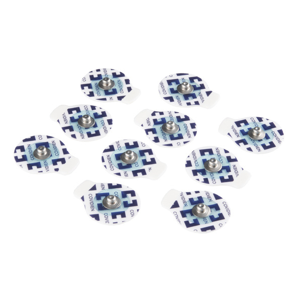
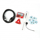
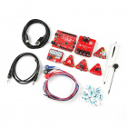
To follow along with this tutorial, you will need the following materials. You may not need everything though depending on what you have. Add it to your cart, read through the guide, and adjust the cart as necessary. You'll need at least three biomedical sensor pads per muscle sensor each time you connect to a muscle group.
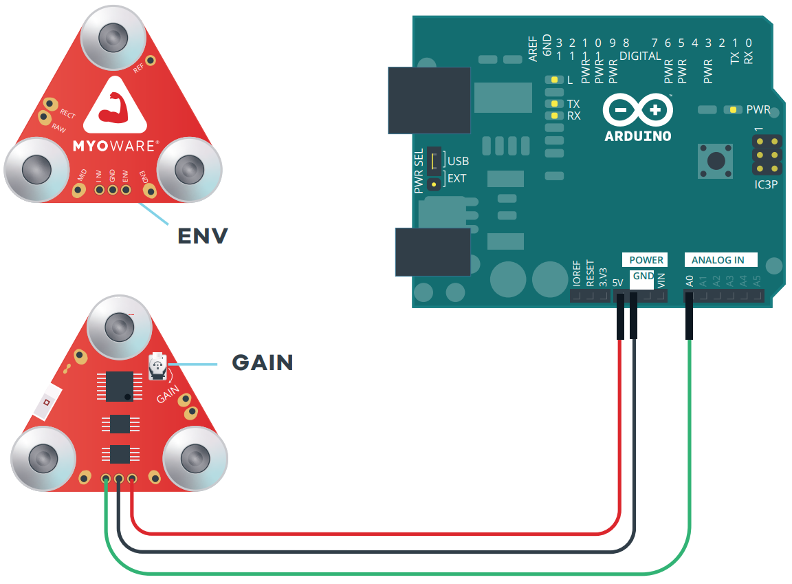
At a minimum, you will need the following parts to connect and power the muscle sensor. You can view the muscle signal from the ENV LED.
You will need the following parts to connect and power the muscle sensor. You can view the magnitude of the muscle signal from the LED segments.
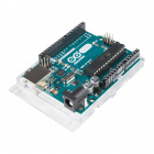
You will need the following to connect an 5V Arduino without the need to solder any wires between boards. Connecting to an Arduino allows you to process sensor data to control a device or viewing the signal on the Arduino Serial Plotter.
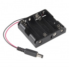
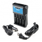
You will need the following to transmit sensor data wirelessly through an Arduino. The Artemis is one option to wirelessly send sensor data. Of course, you will need a minimum of 2x RedBoard Artemis boards and 2x USB cables. You'll need 1x battery pack and 4x AA batteries for each RedBoard Artemis that is battery powered. To follow along with example 3, we recommend the following parts.
An alternative to the Artemis is the ESP32. You will need to ESP32 boards and batteries. Luckily we have the MyoWare 2.0 Muscle Sensor Wireless Kit that provides all that you need!
Depending on your setup, you may need the following accessories to add an extension between the hardware and muscle group.
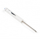
To easily disconnect the boards, we recommend using a flathead screwdriver. The following screwdriver can be used to remove the stack of boards from each other. Depending on the Arduino that you choose, we recommend getting a hobby knife, solder, and soldering iron when changing the jumper pad for the logic levels.
You will also need the following.
If you aren’t familiar with the following concepts, we recommend checking out these tutorials before continuing. Depending on the Arduino development board that you are using, you may need to install drivers. The RedBoards use a different USB-to-serial converter compared to the Arduino Uno. Both the Arduino Uno and the RedBoard Plus use 5V for the logic levels.
For users interested in using a Bluetooth® connection to wirelessly transmit the sensor data, we recommend getting the RedBoard Artemis and installing the board definitions. Note that the RedBoard Artemis uses 3.3V for the logic levels.
The MyoWare 2.0 ecosystem builds upon the previous muscle sensor designs. The major changes to the ecosystem include:
 |
 |
| V1 and V2 Shields Stacked for Comparision | Keyed Connectors Prevent Incorrect Stacking of Boards |
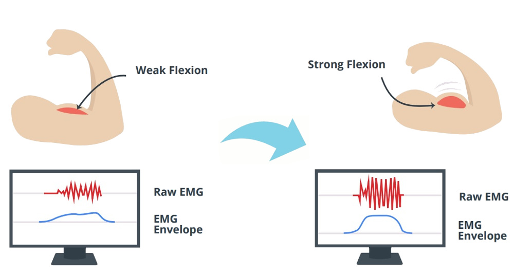
"The MyoWare measures muscle activity through the electric potential of the muscle, commonly referred to as surface electromyography (EMG or sEMG for short). When your brain tells your muscle to flex, it sends an electrical signal to your muscle to start recruiting motor units (the bundles of muscle fibers that generate the force behind your muscles).
The harder you flex, the more motor units are recruited to generate greater muscle force. The greater the number of motor units, the more the electrical activity of your muscle increases. The MyoWare will analyze this electrical activity and output an analog signal that represents how hard the muscle is being flexed. The harder you flex, the higher the MyoWare output voltage will go." -Advancer Technologies
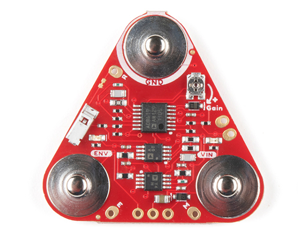
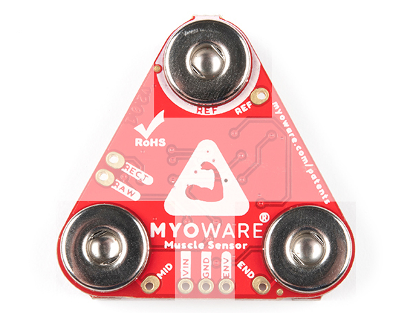
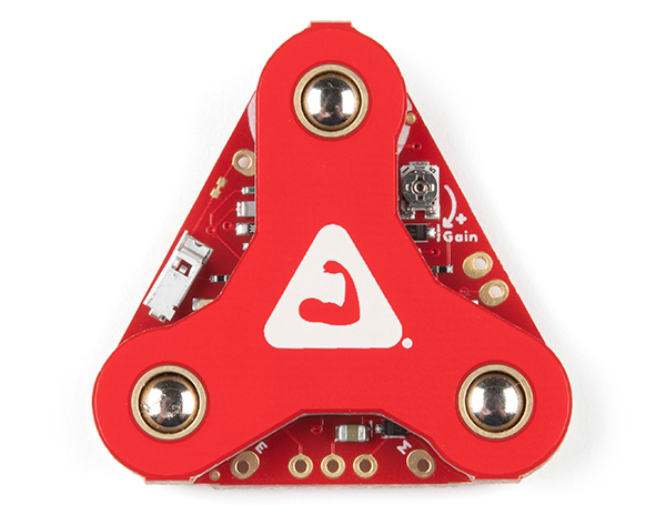
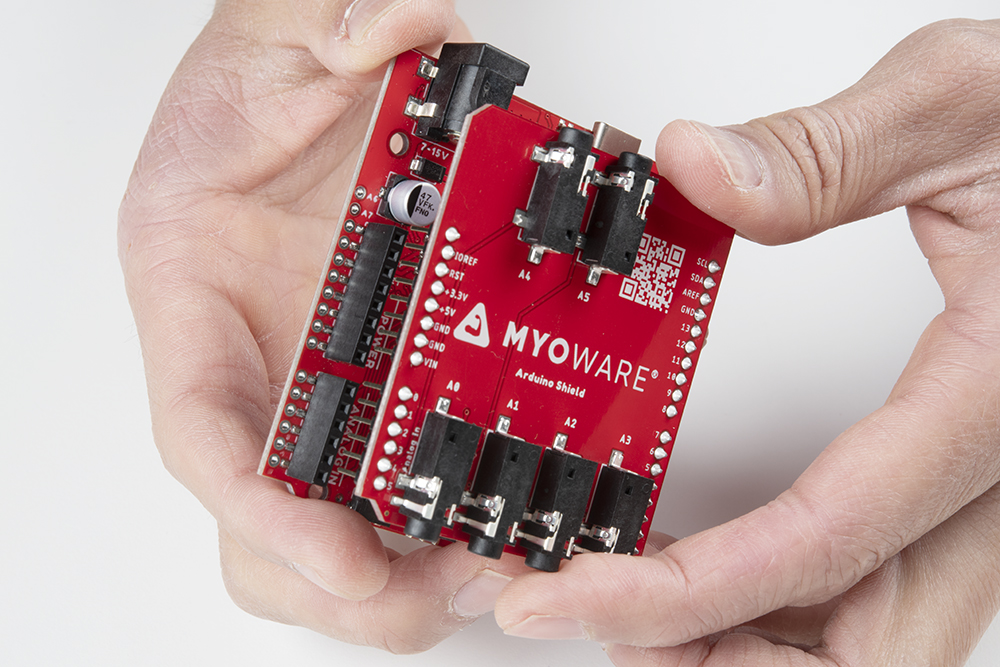
The MyoWare 2.0 Muscle Sensor is an Arduino-compatible, all-in-one electromyography (EMG) sensor from Advancer Technologies! The innovative snap connector system eliminates the need to solder connections for the MyoWare 2.0 ecosystem. It's that easy: stick on a few electrodes (not included), read the output voltage and flex some muscles! The muscle sensor’s snap connector system makes it easier to stack shields together. The top side connectors link to power and the sensor’s EMG envelope output while the bottom side links to the input electrodes. Measuring muscle activity by detecting its electric potential has traditionally been used for medical research. However, with the advent of ever shrinking yet more powerful microcontrollers and integrated circuits, EMG circuits and sensors have found their way into all kinds of control systems such as video games, robotics, and prosthetics!
The embedded snap connectors mate well with our biomedical sensor pad (10 pack).
The top side of the board is populated with the circuit and male snap connectors. The bottom of the board has the female snap connectors.
 |
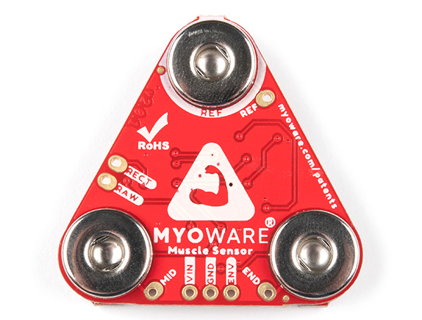 |
| Top Side | Bottom Side |
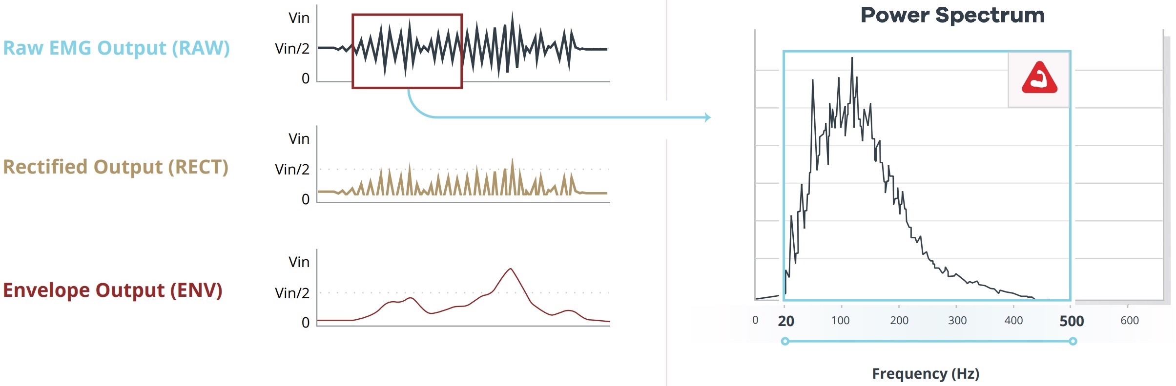
The MyoWare 2.0 Muscle Sensor measures a small EMG reading from the muscle group. This signal goes through an amplifier, bandpass filter, rectifier, and envelope detector so that users can easily read the muscle activity through a microcontroller's ADC pin.

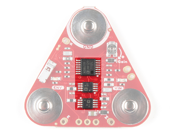
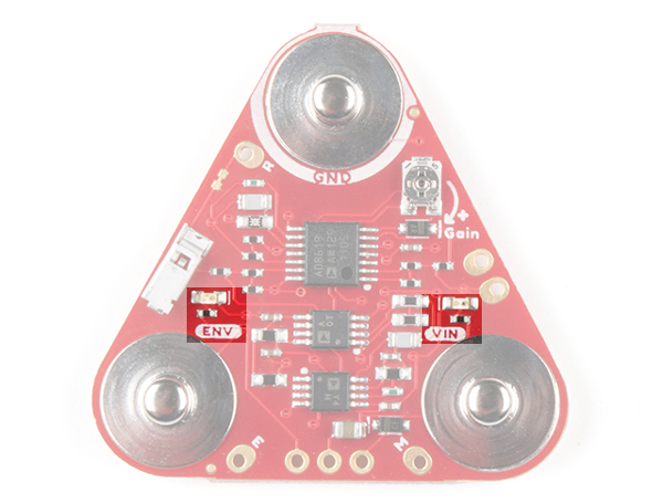
The ICs highlighted below are amplifiers used to help process the raw EMG signal. As stated from the MyoWare 2.0 Advanced Guide, some of the muscle sensor's technical specifications are as follows:
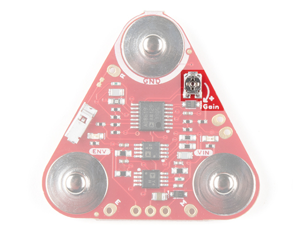
The board includes a potentiometer (trim pot) to manually adjust the gain of the envelope signal. You will need a screwdriver to adjust. Of course the top shield will need to be disconnected to access the potentiometer. The gain (G) for the following signals are as follows:
The image below shows the waveforms for the raw, rectified, and envelope outputs. The graph to the right of the outputs show the raw output's power spectrum. The MyoWare 2.0 Muscle Sensor has a first-order bandpass filter ranging between 20Hz - 500Hz. This range is ideal for capturing the the raw EMG signal and removing any unwanted signals such as motion artifacts. Note that the data shown is for illustration purposes only and not the actual data.
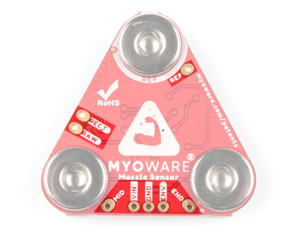
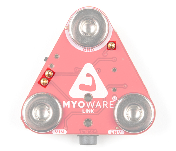
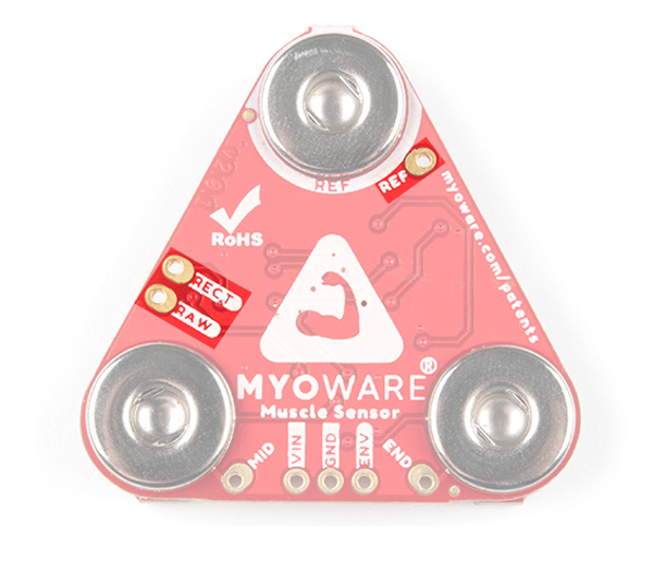
Flipping the board to the bottom side, you will see PTH pads labeled. For those that need to solder wire to connect VIN, GND, and ENV, we have included a 1x3 row of 0.1" spaced PTH pads on the board. Additionally, the RAW, RECT, REF, MID, and END pins are broken out throughout the board. When soldering wire to the REF, RECT, and RAW pins, care must be taken to avoid adding excessive solder to the pins as this may prevent the MyoWare 2.0 Link Shield's pogo pins from connecting properly to the PTH pads.
The board includes two status LEDs.
The board includes snap connectors to easily stack shields on the MyoWare 2.0 Muscle Sensor. The top of the board is slightly offset and designed to act like a key so there's only one way to connect the boards together. Align the GND or REF snap connectors before stacking the boards together. Otherwise, the three snap connectors will fail to connect.
The following male snap connectors are on the top side of the board. These are also broken out on the 1x3 header on the bottom of the board. Flip the board over to view the pin labels.
The following female snap connectors are on the bottom side of the board. These are broken out onto a PTH pad next to each snap connector.
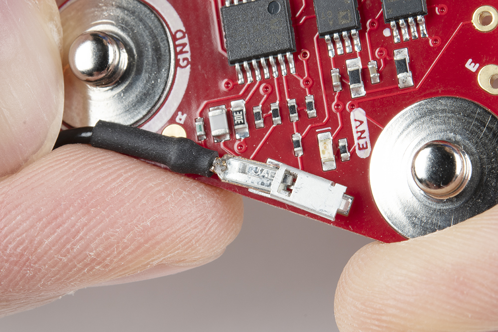
The board has a housing to insert the reference cable's crimped pin. By inserting the pin to its housing and placing a biomedical sensor pad into the electrode snap, you can stick the reference cable to a separate section of the body such as a bony portion of the elbow or a nonadjacent muscle near the targeted muscle where the built-in reference pin is unable to reach.
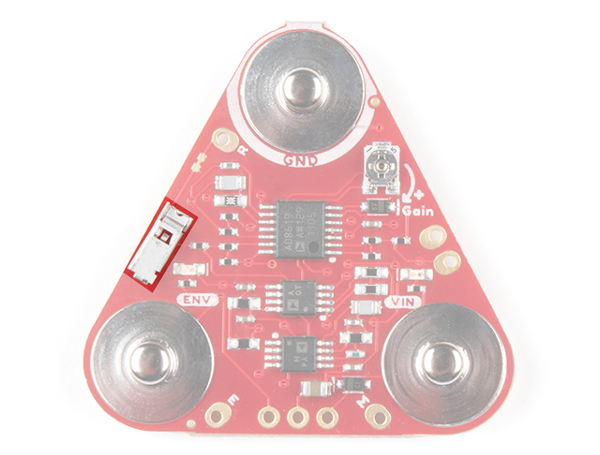
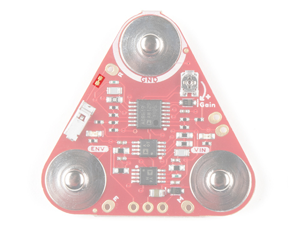
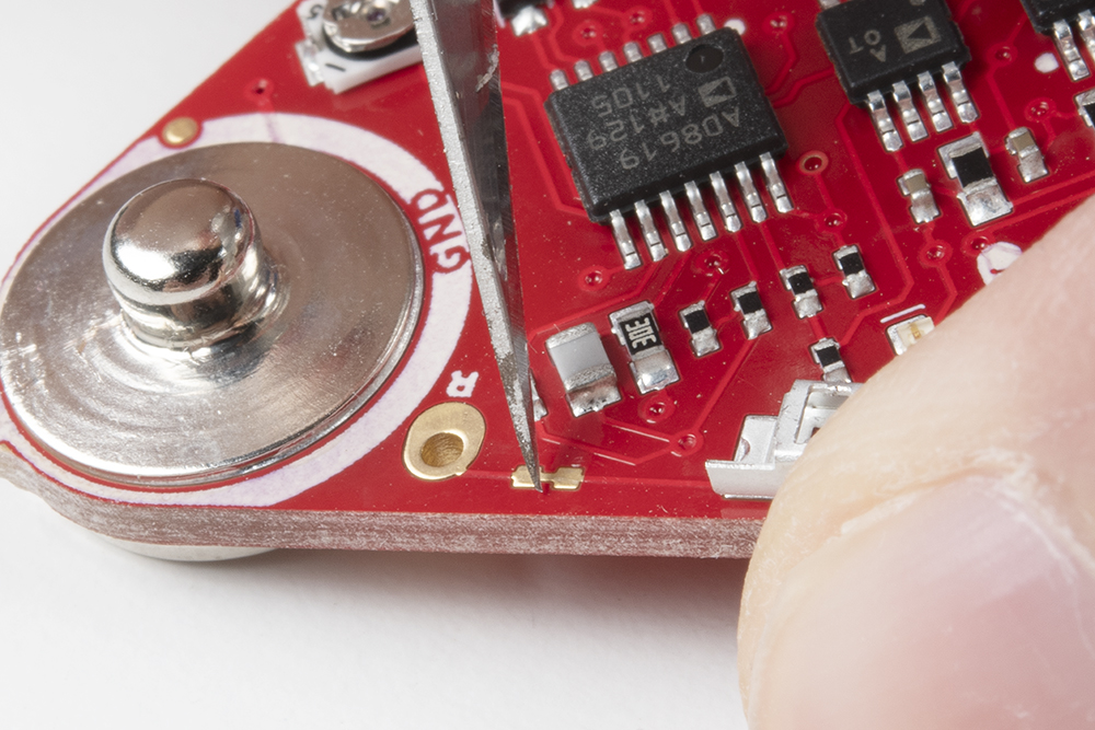
There is a small jumper beside the reference pin labeled "R". This jumper is closed by default and connects to the reference electrode connector. Make sure to cut this trace when using the reference cable. For more information on modifying the jumpers, check out our tutorial on working with jumper pads and PCB traces.
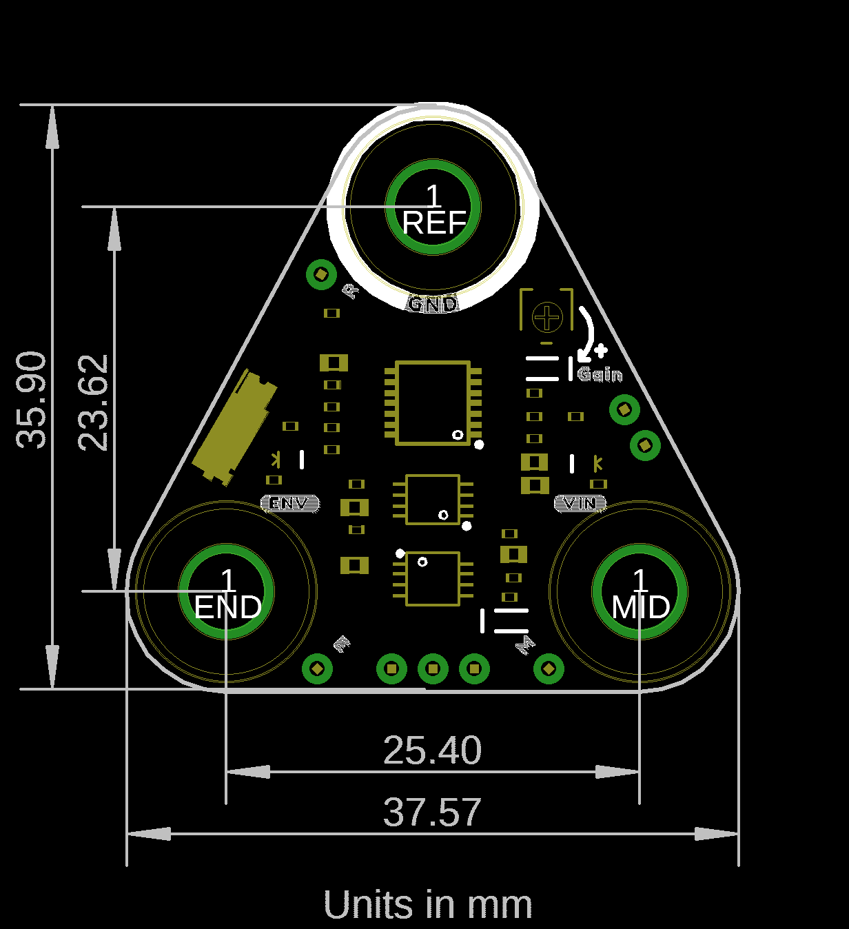
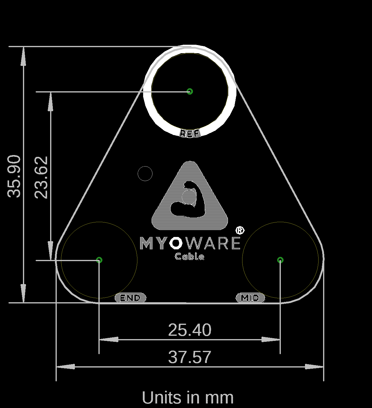
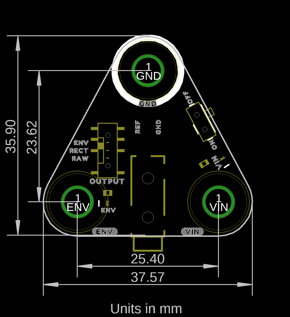
The MyoWare 2.0 Muscle Sensor board dimension is 37.57mm x 35.90mm (1.48” x 1.41”).
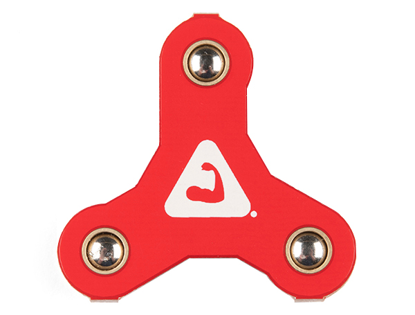
The MyoWare 2.0 Sensor Cover comes pre-installed with each MyoWare 2.0 Muscle Sensor. The cover should remain on the sensor to protect the circuitry unless you decide to stack shields on top.
There's not much going on with this board besides the snazzy design. It looks similar to a fidget spinner... well, that is without the press fit skateboard bearings built into the board. There is no circuitry populated on the board. On the top of the board, you will find the MyoWare logo from Advancer Technologies. On the bottom, you will find a QR code on the bottom of the board. Feel free to take out your smartphone and scan the QR code to head on over MyoWare's official site!
 |
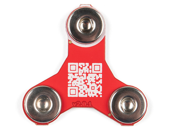 |
| Top Side | Bottom Side |
The sensor cover uses the MyoWare 2.0 Muscle Sensor form factor and has board dimensions of 37.57mm x 35.90mm (1.48” x 1.41”).

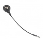
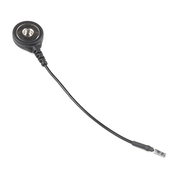
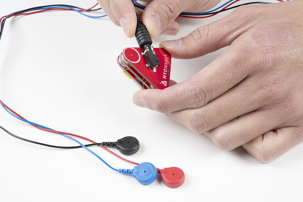
The MyoWare 2.0 Reference Cable is meant as an extension for the MyoWare 2.0 Muscle Sensor's reference pin. By inserting the pin to its housing and placing a biomedical sensor pad into the electrode snap, you can stick the reference cable to a separate section of the body such as a bony portion of the elbow or a nonadjacent muscle near the targeted muscle where the built-in reference pin is unable to reach.
One end of the MyoWare 2.0 Reference Cable has a crimped pin with a tab. This is meant to be inserted into its respective pin housing on the MyoWare 2.0 Muscle Sensor. The tab will lock the pin in place. The other end has a snap pin to connect to a biomedical sensor pad. The cable is about 3 inches long.

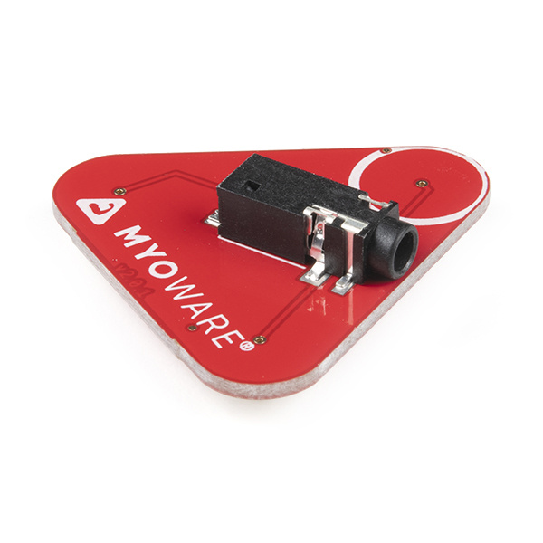
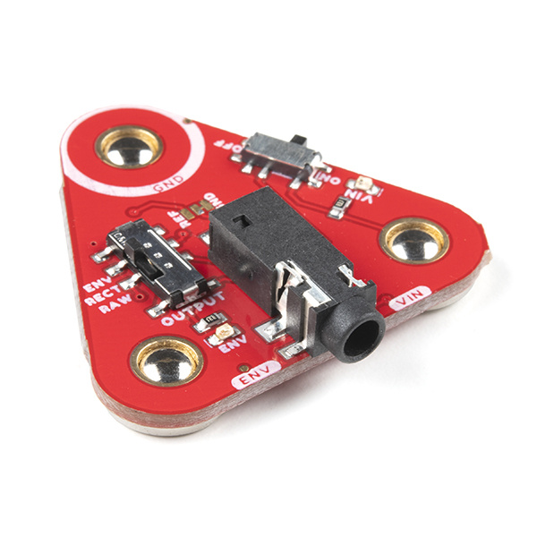
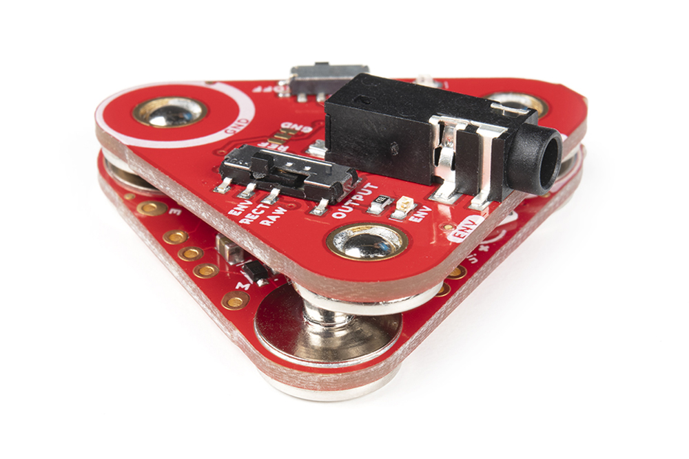
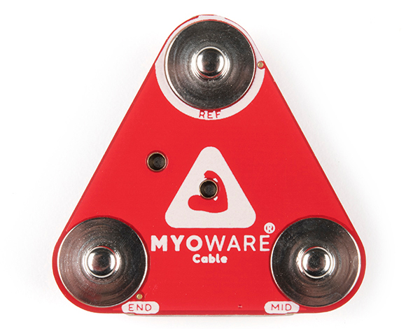
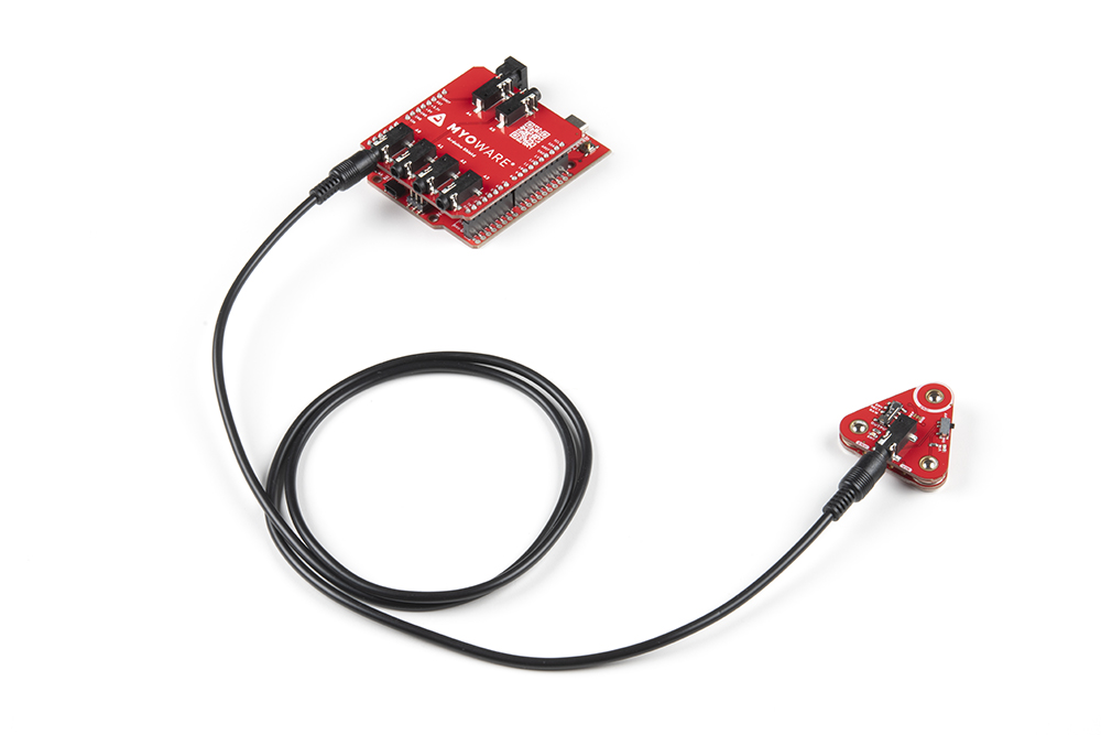
The MyoWare 2.0 Cable Shield is designed for cases where you would want to mount the sensor pads away from the MyoWare 2.0 Muscle Sensor. This allows the users to test and use the muscle sensor without actually attaching the board to the target muscle. The shield includes a 3.5mm TRS jack where you can attach a traditional three electrode sensor cable. The board is also equipped with snap connectors on the board so you can easily stack it. Unlike the other shields in the MyoWare 2.0 ecosystem, this board snaps to the bottom side of the MyoWare 2.0 Muscle Sensor. You'll want to use this shield for non-wearable projects that are housed in an enclosure or that target muscles that are too small or situated such that the on-board electrode sockets would not be suitable.
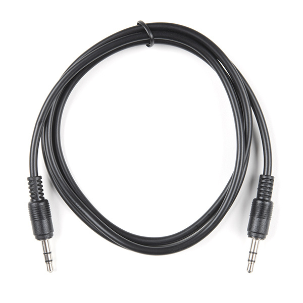
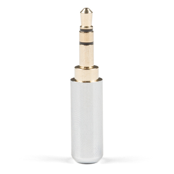
Of course, you will need a 3.5mm TRS connector to access the mid, end, and reference ground pins along with a few biomedical sensor pads. Make sure to grab the following products if you do not have them already.
Or you could grab a TRS plug to make an adapter using conductive material.
While the default image for the MyoWare 2.0 Cable Shield's product page shows the side with the 3.5mm TRS connector as the first image, the "top" of this board is the side with male snap connectors. Compared to the other shields in the MyoWare 2.0 ecosystem, this is the only shield that stacks to the bottom side of the MyoWare 2.0 Muscle Sensor.
 |
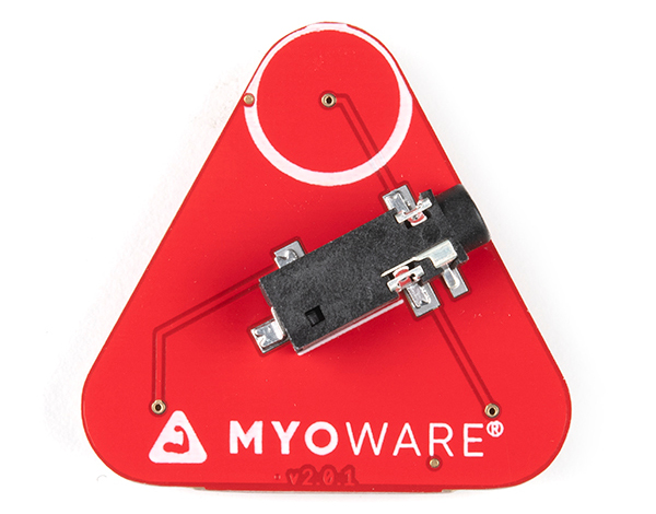 |
| Top Side | Bottom Side |
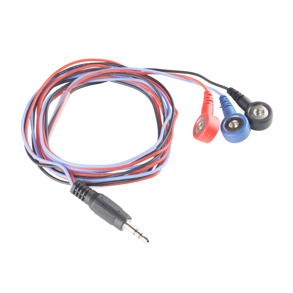
The cable color codes can vary depending on the manufacturer. If you are seeing unusual sensor readings and the MyoWare 2.0 Muscle Sensor is not responding to a muscle group, try testing the pinout by using a multimeter set to measure continuity. Below is a table that references the connections between the male snap pins, TRS connector, and cable. The male snap pins allow users to easily stack to the bottom of the MyoWare 2.0 Muscle Sensor
| Snap Connector | TRS Pinout | Electrode Pin Color [CAB-12970] |
Notes |
|---|---|---|---|
| Reference [REF] | Sleeve | Black | Reference electrode connection. Connect this to a separate section of the body such as a bony portion of the elbow or a nonadjacent muscle near the muscle group. |
| End [END] | Ring | Blue | End muscle electrode connection. Connect to the end of the muscle group. |
| Middle [MID] | Tip | Red | Middle muscle electrode connection. Connect to the middle of the muscle group. |
The shield uses the MyoWare 2.0 Muscle Sensor form factor and has board dimensions of 37.57mm x 35.90mm (1.48” x 1.41”).
 |
 |
| v 2.0.3 | v 2.0.2 |
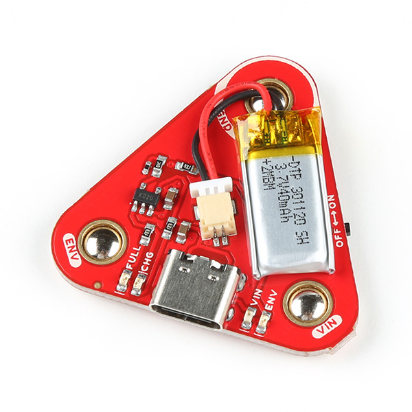
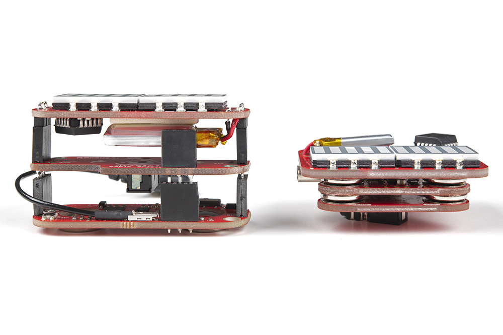
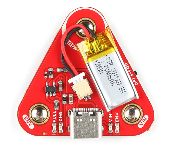
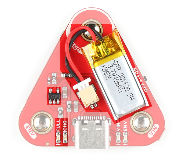
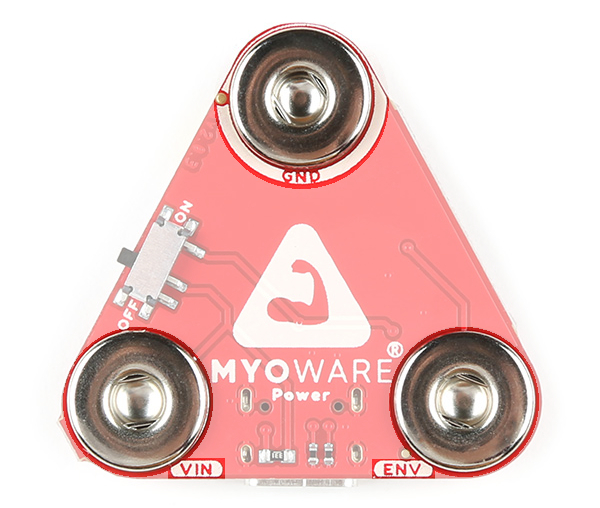
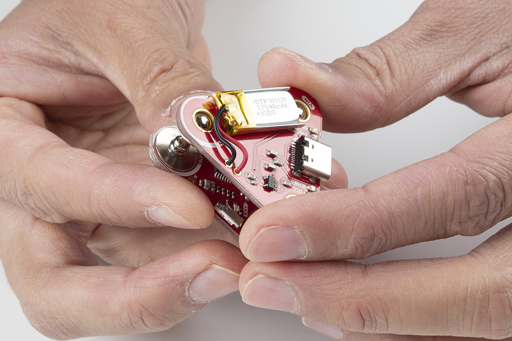
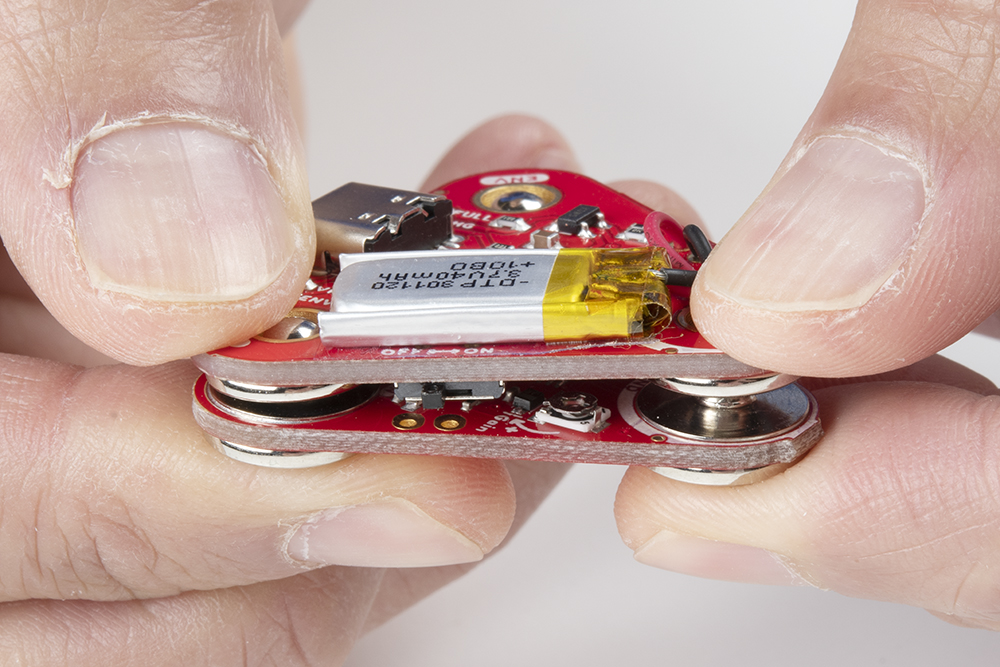
The MyoWare 2.0 Power Shield is designed to easily power the MyoWare 2.0 Muscle Sensor for remote applications. The MyoWare Power Shield is equipped with snap connectors on the board so you can easily stack it to the top side of the MyoWare Muscle Sensor. Flip the switch to the ON position to give the sensor all the power it needs to work its myoelectric magic. Connecting the MyoWare 2.0 Muscle Sensor to battery power allows for a cleaner signal while also eliminating the possibility of creating a dangerous current path to the power grid. Use it to power your sensor in portable applications.
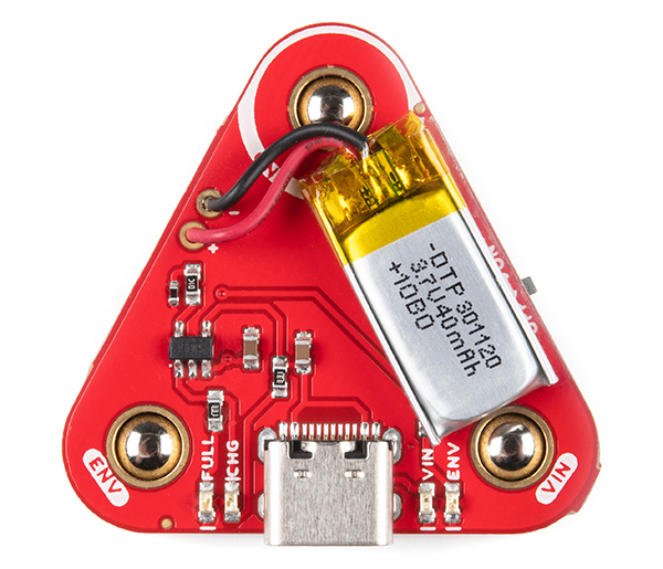
The top side of the board has the LiPo battery and the USB connector. The bottom side has the female snap connectors and a power switch.
|
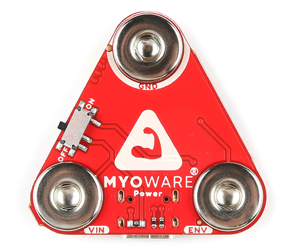 |
| Top Side | Bottom Side |
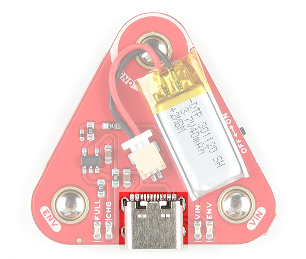
Included on the board is a USB Type C connector. Plug in a USB C cable to a 5V power source to charge the single cell LiPo battery.
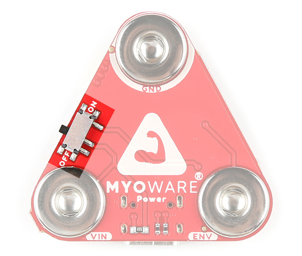
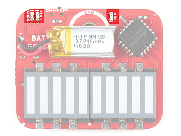
The board includes a power switch. Flip the switch to the ON position to provide power to the MyoWare 2.0 Muscle Sensor via the VIN female snap connector. When not in use, flip the switch to the OFF position.
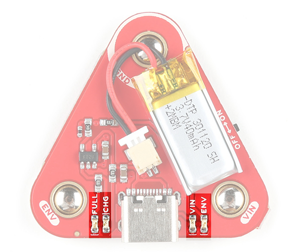
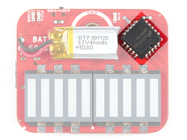
The board includes the MCP73831 LiPo charger IC (the little black IC with 5 pins) to safely charge a single cell LiPo battery. In this case, the charge rate is set to 40mA to charge the built-in 40mAh LiPo battery. The charge status of your battery is indicated by the charge (CHG) and full (FULL) LEDs.
The board includes three female snap connectors to easily stack on top of the MyoWare 2.0 Muscle Sensor:
The board includes four LEDs on the top side of the board:
The shield uses the MyoWare 2.0 Muscle Sensor form factor and has board dimensions of 37.57mm x 35.90mm (1.48” x 1.41”).
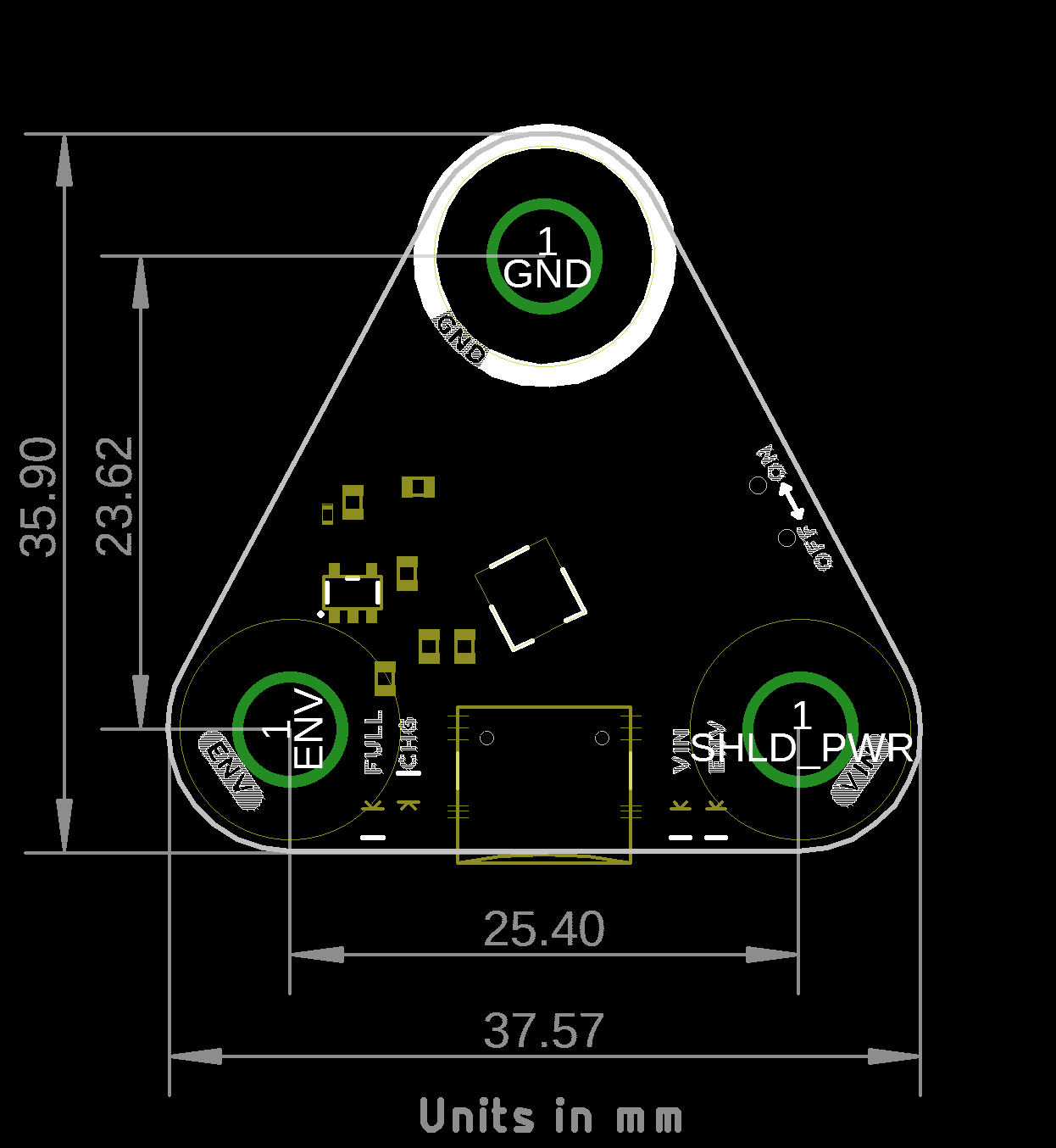
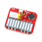
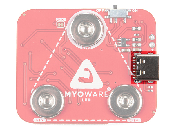
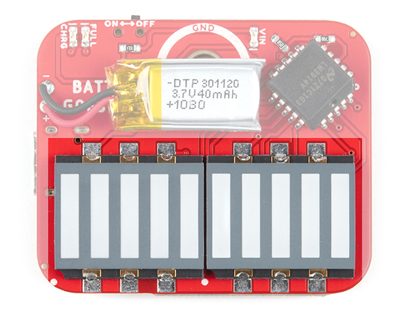
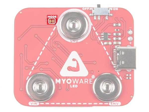
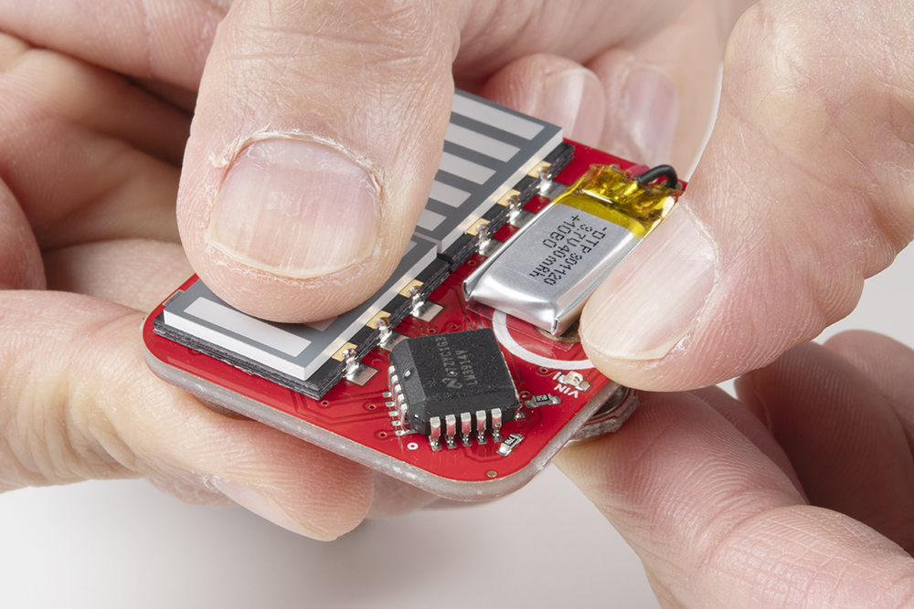
The MyoWare 2.0 LED Shield is designed to display the magnitude of a target muscle's signal and power the MyoWare 2.0 Muscle Sensor with its built-in battery. The blue 10-segment bar graph shows the magnitude of the measured signal. The more muscle activation measured, the higher up the board LEDs will go! With this shield, you will be provided with a visual representation of the signals provided by the MyoWare 2.0 Muscle Sensor. The LED shield is equipped with snap connectors on the board so you can easily stack it on the top side of the MyoWare 2.0 Muscle Sensor and flip the switch to the ON position to give the sensor all the power it needs to work its myoelectric magic. Connecting the MyoWare 2.0 Muscle Sensor to the battery power allows for a cleaner signal while also eliminating the possibility of creating a dangerous current path to the power grid. Use it to gauge how hard you’re working a muscle during a workout, as a teaching tool, or add some myoelectric flair to your Halloween costume!
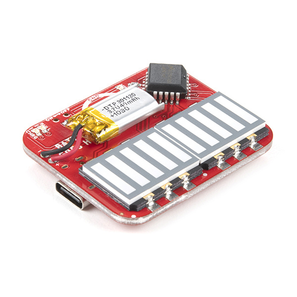
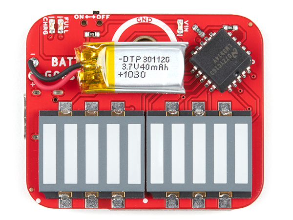
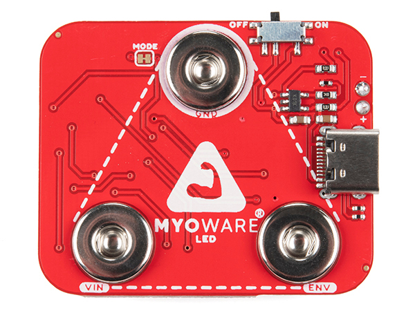
The top side of the board has the LEDs and LiPo battery. The bottom side has the female snap pins, power switch, and USB connector.
 |
 |
| Top Side | Bottom Side |
Included on the board is a USB Type C connector. Plug in a USB C cable to a 5V power source to charge the single cell LiPo battery.
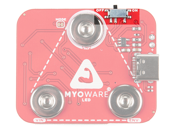
The board includes a power switch. Flip the switch to the ON position to provide power to the MyoWare 2.0 Muscle Sensor via the VIN's female snap connector. When not in use, flip the switch to the OFF position.
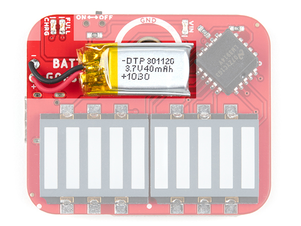
The board includes the MCP73831 LiPo charger IC to safely charge a single cell LiPo battery. In this case, the charge rate is set to 40mA to charge the 40mAh LiPo battery on the board. The charge status of your battery is indicated by the charge (CHRG) and full (FULL) LEDs.
 |
 |
| Top Side | Bottom Side |
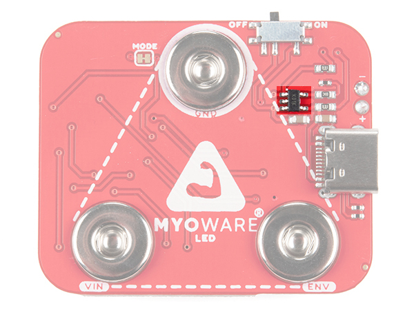
The black square IC is the LM3914 Dot/Bar Driver. This IC takes the output from the muscle sensor and outputs it to the 2x5 segment LEDs.
The board includes three status LEDs.
Of course, this board would not be called the MyoWare 2.0 LED Shield if it did not have the large segment LEDs. The bar graph lights up corresponding to the level of the muscle signal measured. The minimum is closest to the dot bar driver IC. As there is more muscle activity, the voltage will increase from the ENV pin. As a result, the LEDs will continue to light up until the last one on the other side is lit. The LEDs are bright enough to be seen in full light, but really glow nice in low light.
The board includes three female snap connectors to easily stack on top of the MyoWare 2.0 Muscle Sensor:
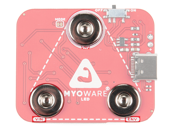
The board includes one jumper for the MODE that is closed by default. The MODE is wired directly to LM3914 Dot/Bar Driver's V+ pin for bar graph mode. In this mode, the LED segments will continue to light up based on the magnitude of the muscle signal until the last one on the other side is lit. Opening the MODE jumper will turn the board into dot mode. When dot mode is enabled, a leading LED bar (i.e. "dot") will light up and traverse the segments. Any trailing LEDs behind it will be turned off instead of filling in with light. For more information on modifying the jumpers, check out our tutorial on working with jumper pads and PCB traces.
The shield uses the MyoWare 2.0 Muscle Sensor form factor. The board dimension is different than the other boards: 46.15mm x 38.00mm (1.82” x 1.50”).

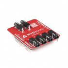
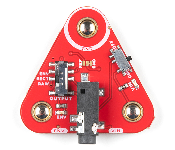
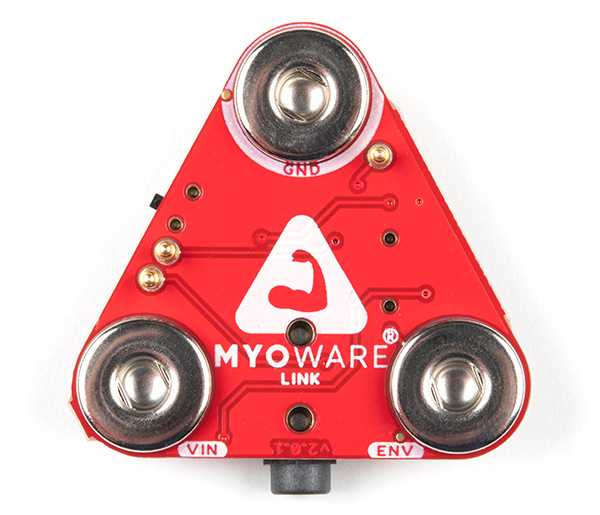
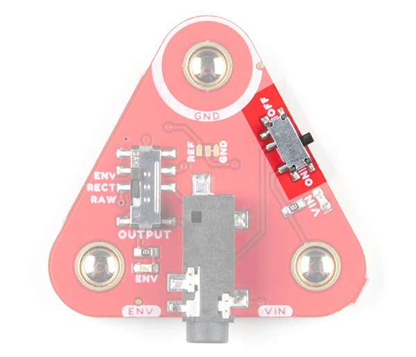
The MyoWare 2.0 Link Shield is designed to easily connect a MyoWare 2.0 Muscle Sensor to your Arduino microcontroller. The shield provides a 3.5mm TRS jack so that you can use a 3.5mm TRS-to-TRS cable to link the boards together. The MyoWare 2.0 Link Shield is equipped with snap connectors on the board so you can easily stack it to the top side of the MyoWare 2.0 Muscle Sensor. You'll need the MyoWare 2.0 Arduino Shield and a development board with the Arduino Uno R3 footprint to link each MyoWare 2.0 Muscle Sensor and Link Shield stack.
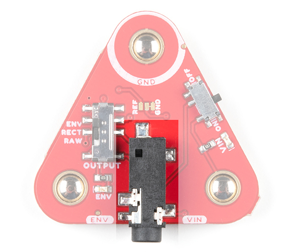
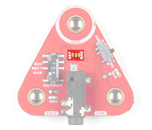
The top side of the board has the TRS connector, power and output switches. The bottom side of the board includes the female snap connectors.
 |
 |
| Top Side | Bottom Side |
The power switch turns MyoWare 2.0 Muscle Sensor on and off. Power is provided by your Arduino and the Arduino Shield. By default, power is set to 5V on the Arduino Shield. The ring pin of your TRS-to-TRS cable will connect the 5V to VIN when the switch is flipped to the ON position.
The OUTPUT switch selects the signal to provide for the Arduino's analog input.
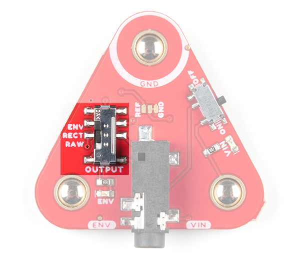
The 3.5mm TRS connector is connected to the following pins.
| Pinout | TRS Pin |
|---|---|
| Ground [GND] | Sleeve |
| Voltage Input [VIN] | Ring |
| ENV/RECT/RAW [OUTPUT] | Tip |
The board includes two LEDs.
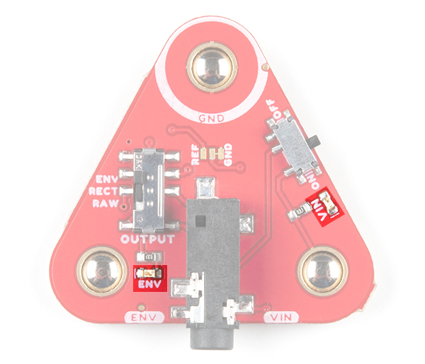
The board includes three female snap connectors to easily stack on top of the MyoWare 2.0 Muscle Sensor:
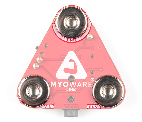
There are three pogo pins on the bottom of the board. These have a much lower profile than the other pogo pins that you may have seen in our storefront. These connect to the MyoWare 2.0 Muscle Sensor's PTH pads. Note that the MyoWare 2.0 Link Shield does not have any labels for the pins. The pogo pin closest to the GND snap connector is the reference pin. The pogo pin just next to the switch is the rectified output pin. The pogo pin just above the VIN snap connector is the raw output.
 |
 |
| Pogo Pins on the MyoWare 2.0 Link Shield | PTH Pads on the MyoWare 2.0 Muscle Sensor |
The board includes a 3-way jumper on the top of the board. The point of this jumper is to allow users to change the relative ground point for the output and Arduino. By default, the RAW output will be centered around VIN/2, which is what REF is. Some users might want to change this so that it is centered around 0V, which would require changing the relative ground point to REF. Cutting the trace connected to GND and adding a solder jumper between the REF and center pad will connect the REF pogo pin to the muscle sensor's REF. For more information on modifying the jumpers, check out our tutorial on working with jumper pads and PCB traces.
The shield uses the MyoWare 2.0 Muscle Sensor form factor and has board dimensions of 37.57mm x 35.90mm (1.48” x 1.41”).
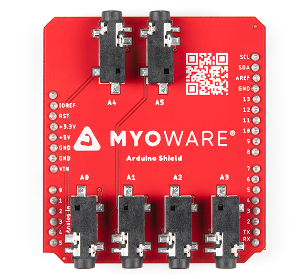
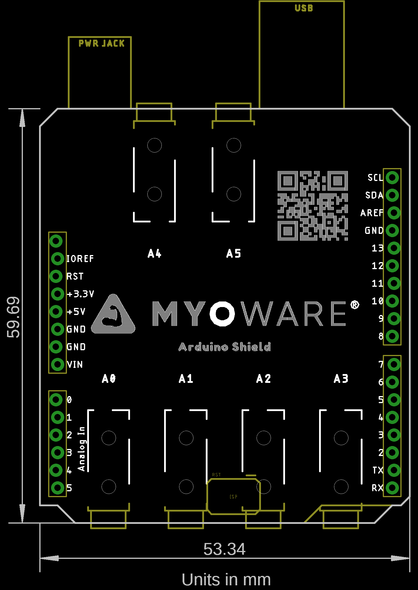
The MyoWare 2.0 Arduino Shield is designed to easily connect up to six MyoWare 2.0 Muscle Sensors and Link Shields using 3.5mm TRS-to-TRS audio cables. The board comes pre-populated with male headers so all you need to do is stack it on your Arduino and connect the sensors to read up to six muscle groups! The Arduino shield form-factor mates directly with development boards that have the Arduino Uno R3 standard footprint. You'll need a MyoWare 2.0 Link Shield and TRS-to-TRS cable for each MyoWare 2.0 Muscle Sensor.
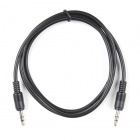
You'll need a TRS-to-TRS cable to link the boards together. Of course, you could solder wire to a TRS connector as well to make your own. Just make sure to solder wires to the correct pins.
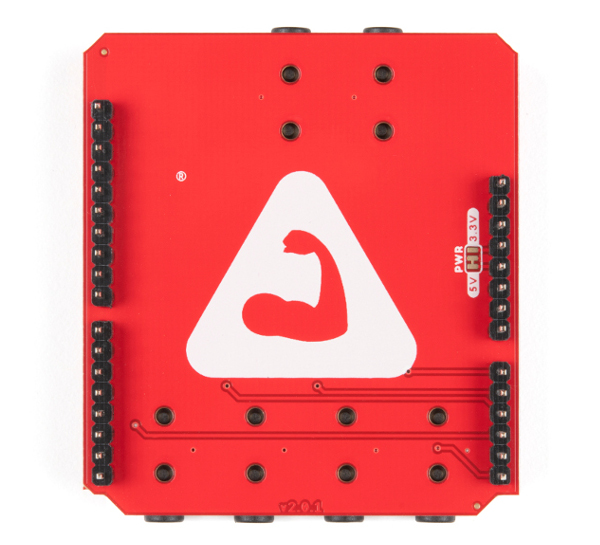
The top side of the board includes the TRS connectors and the QR code. Feel free to take out your smartphone and scan the QR code to head on over MyoWare's official site! The bottom side has the male headers to mate with female headers on Arduino development boards with an R3 footprint.
 |
 |
| Top Side | Bottom Side |
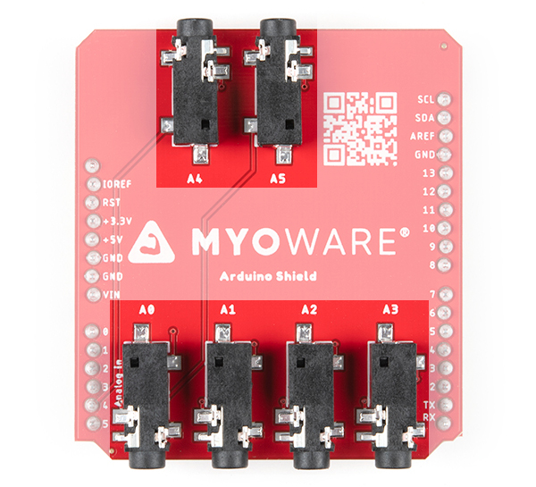
On the top side of the board you will find six 3.5mm TRS jacks. Each connector is connected to power and your Arduino's analog pins ranging from A0 to A5.
The 3.5mm TRS Connector is connected to the following electrode pins.
| Electrode Pin | TRS Pin |
|---|---|
| Ground [GND] | Sleeve |
| Voltage [VIN] | Ring |
| ENV/RECT/RAW [OUTPUT] | Tip |
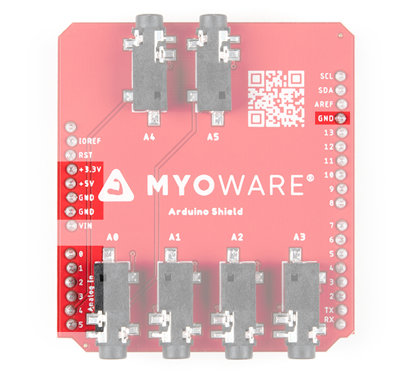
The 5V, 3.3V, GND net, and analog pins (A0 - A5) are reserved for the shield.
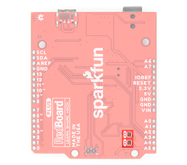
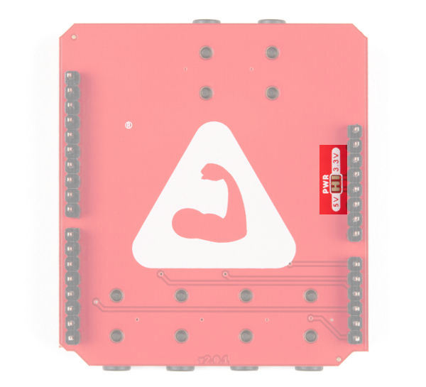
There's not too much going on the bottom of the board. On the back, there is a jumper labeled as PWR. By default, the 3-way jumper connects the 5V pin and the 5V plane on the back of the board. The center pad is connected to the TRS connectors to power any MyoWare 2.0 Muscle Sensors through the Link Shield. Cut the trace and add a solder blob between the center pad and 3.3V for an alternative voltage. For more information on modifying the jumpers, check out our tutorial on working with jumper pads and PCB traces.
The shield uses the Arduino Uno R3 form factor and has board dimensions of 53.34mm x 59.69mm (2.10” x 2.35”).
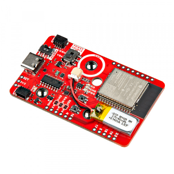
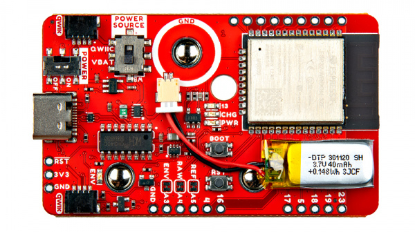
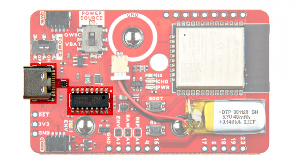
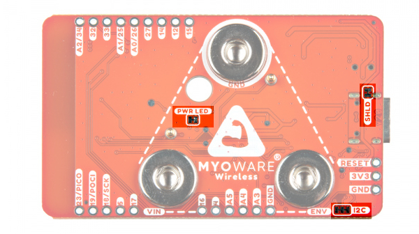
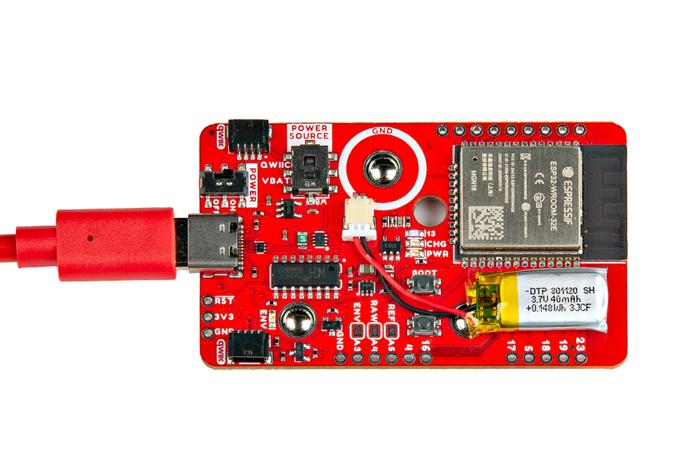
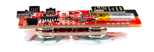
The MyoWare® 2.0 Wireless Shield is designed to take in readings from the MyoWare 2.0 Muscle Sensor and wirelessly transmit sensor data with the ESP32-WROOM! This shield also includes a built-in LiPo battery to remotely power both the muscle sensor and the ESP32 module. The Wireless Shield is equipped with snap connectors and low profile pogo pins on the board so you can easily stack it on the top side of the MyoWare 2.0 Muscle Sensor. Simply select a Power Source and flip the power switch to the ON position to give the sensor all the power it needs to work its myoelectric magic.
 |
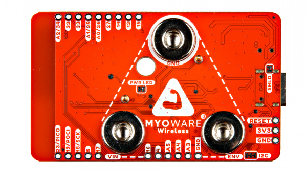 |
| Top Side | Bottom Side |
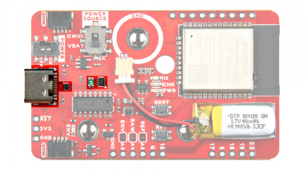
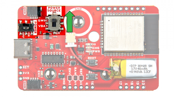
There are a variety of power and power-related nets broken out to connectors and through hole pads. How the Wireless shield is powered will depend on the configuration of the switches. Let's take a look at the options below.
A USB type C connector is included to power and program the ESP32. There are ESD protection diodes connected to the USB's data lines, a resettable fuse, and ideal diodes for reverse polarity protection on the USB and battery nets. You can also view serial data between the microcontroller and computer. When connected to the MyoWare 2.0 Muscle Sensor, however, we recommend sending data wirelessly to reduce the chance of introducing noise to the system and safeguard against electrical shock from the power grid. The USB connector is also used to charge the LiPo battery.
You will need to make sure that the switches are flipped to the proper sides to power the ESP32. Check below about the switches for more information.
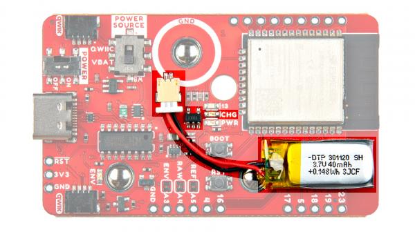
The board includes the MCP73831 LiPo charger IC (the little black IC with 5 pins) to safely charge a single cell, LiPo battery. In this case, the charge rate is set to about 40mA to charge the built-in 40mAh LiPo battery. Compared to other LiPo batteries on SparkFun's catalog, this one uses a smaller 2-pin, 1.00mm pitch JST-SH connector.
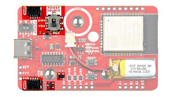
There are two switches on the board.

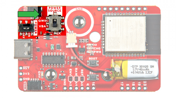
The Power Source is a triple pole, double throw (TPDT) switch. Flipping the switch to the VBAT position will connect the power source net to the 3.3V voltage regulator's output. This also connects the 3.3V voltage regulator's output to the Qwiic's 3.3V pin. Placing the switch in this position will connect the input of the voltage regulator to the upstream source (i.e. voltage from the USB or LiPo Battery).
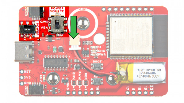
Flipping the switch to the QWIIC position will connect the power source net to the Qwiic's 3.3V pin. This also will disconnect the output from the 3.3V voltage regulator from everything. This allows you to power the MyoWare 2.0 Wireless Shield through the Qwiic connectors. Additionally, it will disconnect the input of the voltage regulator from the upstream source (i.e. voltage from the USB or LiPo Battery).
The switch labeled as Power ON/OFF, is a single pole, single throw (SPST) switch. Flipping the switch to the ON position, this connects the power source net to 3.3V net.
Flipping the switch to the OFF position will disconnect the power source net to 3.3V. This also disconnects the VREG input from any upstream sources. This removes power to the 3.3V voltage regulator regardless of the TPDT switch position.

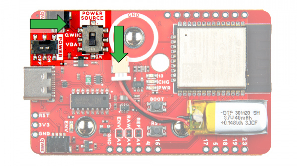
Voltage from the USB connector and LiPo battery is regulated down to 3.3V with the low power voltage regulator (RT9080). It can provide up to 600mA of output current for the system. The output of this voltage regulator will connect to the 3.3V PTH when the Power Source is flipped to the VBATT position. For users that decide to power the board through the Qwiic connector or PTH, you will need to flip the Power Source's switch to the QWIIC position and ensure that you are providing a regulated voltage of 3.3V. The snap connector on the bottom of the board is also connected to 3.3V. This will provide power to the MyoWare 2.0 Muscle Sensor.
The board includes a CH340 USB-to-serial converter. The chip can be used to send serial data between the microcontroller's hardware serial UART and the computer's USB port. This chip is also used to upload code to the ESP32 using the Arduino IDE.
The driver should automatically install on most operating systems. However, there is a wide range of operating systems out there. You may need to install drivers the first time you connect the chip to your computer's USB port or when there are operating system updates. For more information, check out our How to Install CH340 Drivers Tutorial.
The board includes three female snap connectors to easily stack on top of the MyoWare 2.0 Muscle Sensor:
39 / A3.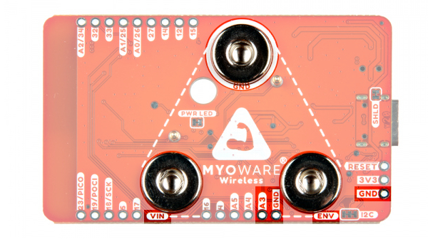
There are two pogo pins on the bottom of the board. These have a lower profile than other pogo pins that you may have seen in SparkFun's catalog . These connect to the MyoWare 2.0 Muscle Sensor's PTH pads. Note that MyoWare 2.0 Wireless Shield does not have any labels for these pogo pins. The pogo pin closest to the GND connector is the reference pin. The pogo pin by VIN is for the raw output.
35 / A5.36 / A4.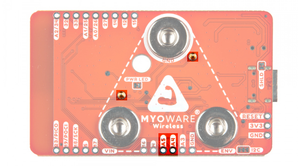
The "brains" of the board is the ESP32-WROOM module. Its pins are broken out to various components on the board, PTHs on the edge of the board, low profile pogo pins, and snap connectors.
 |
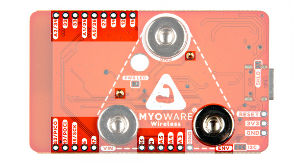 |
| ESP32 Broken Out to PTHs, Components | ESP32 Broken Out to PTHs, Snap Connectors, and Pogo Pins |
Each board includes two momentary buttons: one button for RESET and another for the bootloader mode (i.e. BOOT). Hitting the reset button will restart the ESP32 processor. The BOOT button is used to set the board in bootloader mode. Pressing down on the button as the board is powering up or when it is reset will set the board in bootloader mode. The BOOT button also acts as a general purpose button for user input and it is connected to the ESP32 on pin 0. If you decide to use the button, you will need to write a condition statement to do something after pressing the button.
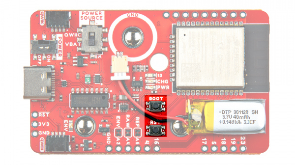
setup(). Need an idea for writing code for the general purpose button? We recommend looking at the SparkFun Inventor Kit V4.1 - Circuit 2B: Trumpet example! pinMode(10, INPUT_PULLUP);If you aren't familiar with the Qwiic Connection System, we recommend reading here for an overview.
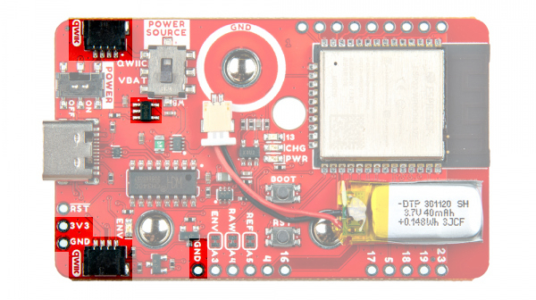
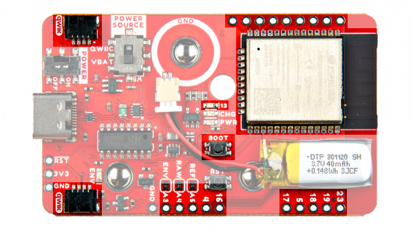
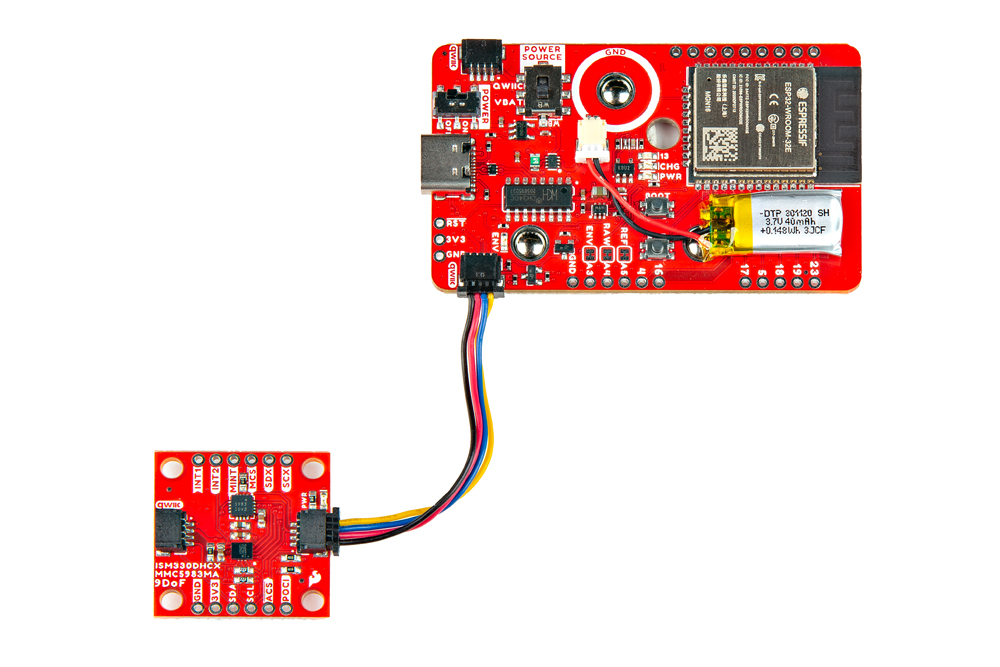
The board includes two horizontal Qwiic connectors. These are the 4-pin, 1mm JST-SH style connectors. These are connected to the ESP32 module's I2C pins. The I2C data and clock lines are also tied to 2.2kΩ pull-up resistors (not highlighted in the image) and transistors for isolation. Make sure to select a power source for your Qwiic-enabled devices using the "Power Source" switch. This allows users to connect Qwiic-enabled devices to the board. Try adding a Qwiic enabled device to monitor the orientation of your arm!
There are four LEDs on the board:
| Charge State | LED status |
| No Battery | Floating (should be OFF, but may flicker) |
| Shutdown | Floating (should be OFF, but may flicker) |
| Charging | ON |
| Charge Complete | OFF |
13. When using the default firmware, the LED will blink when not connected to a Bluetooth device. When the MyoWare 2.0 Wireless Shield is connected to a Bluetooth device, it will stay on.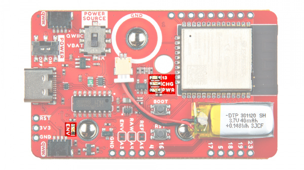
There are jumpers available on the top and bottom of the board. The following three jumpers are on the top side of the board.
35 / A5. Cut this to break the connection between the reference pin and the GPIO pin.36 / A4. Cut this to break the connection between the raw pin and the GPIO pin.39 / A3. Cut this to break the connection between the envelope pin and the GPIO pin.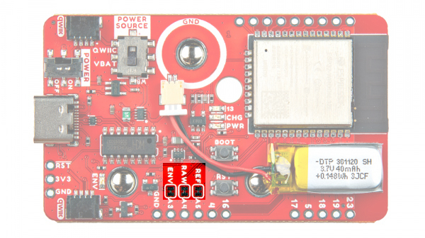
On the bottom side, there are three sets of jumpers.
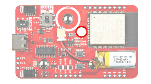
There is a small through hole on the MyoWare Wireless Shield for a precision Phillip's head. This is to manually adjust the potentiometer (trim pot) to change the gain of the envelope signal. As stated earlier in the hardware overview for the MyoWare 2.0 Muscle Sensor, the default gain should be sufficient for most applications. Take care when rotating the trim pot since it can be damaged by over rotating or applying too much pressure.
For users that need to adjust the default gain for a muscle group, we recommend turning the shield's POWER Switch to the OFF position and adjusting the gain down so that the maximum effort muscle contraction peaks just below VIN / 3.3V. Then turn the shield back on, connect the Bluetooth devices, and send the serial data wirelessly to a BLE central device to view the data.
The board dimension is 63.5mm x 38.000mm (2.50" x 1.50").
Advancer Technologies has provided a Quick Start and Advanced Guide for the MyoWare 2.0 Muscle Sensor. Feel free to check them out with this guide.
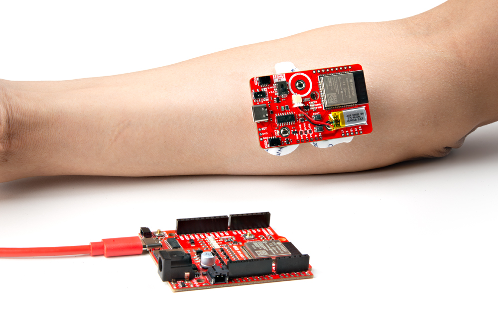
Select a muscle group to place the MyoWare 2.0 Muscle Sensor. Placement of the sensor is critical when measuring the muscle activity. You will need to connect the MID electrode to the middle of the muscle body with the END electrode lined up in the direction of the muscle length. The REF electrode will be adjacent to the muscle body.
We'll be using the forearm as an example. You can connect the sensor to any muscle group as long as orient the sensor's electrodes with respect to the target muscle as explained above. Note that the muscle group shown in the image below are not to scale.
For more other muscle groups, check out the MyoWare 2.0 Advanced Guide. Make sure to zoom in on the image for a closer look at the muscle group. The positions shown in the image are approximate.

Grab an alcohol swab to clean the skin where the MyoWare 2.0 Muscle Sensor will be placed. Cleaning the skin with soap can leave a residue on the skin and should be avoided.

Clean the skin where the EMG pads will stick using an alcohol swab. A cotton ball soaked in isopropyl alcohol is also sufficient to remove any oils or surface contaminants on the skin. Allow the isopropyl alcohol to evaporate before sticking the EMG pads on the skin
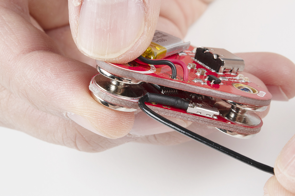
Since the shields are keyed, there's only one way to stack the boards together! Just look for the snap connector labeled as GND or REF. Align the snap connectors. Make sure the power switch is flipped to the OFF position for shields.
Push down on the snap connectors using your thumb and index finger. Make sure to avoid pressing down on the built-in LiPo battery.
 |
 |
Snap the EMG pads to the bottom of the MyoWare 2.0 Muscle Sensor. For users using the MyoWare 2.0 Cable Shield, you'll be snapping it to the sensor cable's snap connectors.
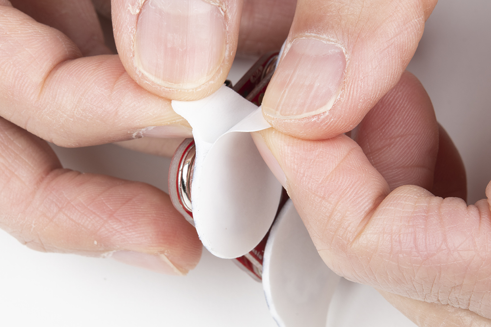
Peel and carefully remove the backs of the electrodes to expose the adhesive.
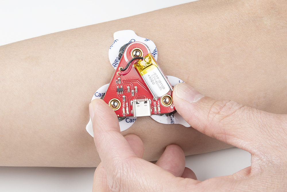
Attach the pads to the target muscle. In this case, we are using our right forearm.
Ensure that power is disconnected when stacking shields on the top side of the MyoWare 2.0 Muscle Sensor. Once everything is connected, flip the power switch to the ON position on the Power Shield or LED Shield. For users connecting the sensor to an Arduino and computer, check to make sure that your computer is not connected to the wall outlet. Then flip the power switch to the ON position on the Link Shield.

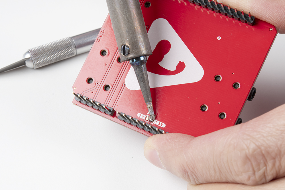
For users using a 3.3V Arduino, we recommend adjusting the PWR jumper by cutting the default trace and adding a solder jumper between the center pad and the 3.3V side. For users using a 5V Arduino, you can leave the jumper connected to the 5V side. For more information on modifying the jumpers, check out our tutorial on working with jumper pads and PCB traces.
Stack the Arduino Shield on your chosen development board with the Arduino Uno R3 footprint.
Insert the TRS cable between the MyoWare 2.0 Link Shield and Arduino Shield's TRS connector. In this case, we will be using the connector labeled as A0. Make sure to adjust the code when using the other channels.
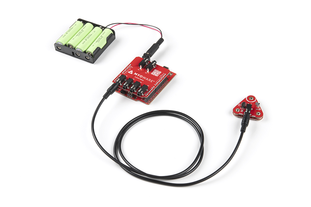
For remote applications, we recommend using a battery pack. In this case, we used AA batteries (NiMH) and a 4xAA battery pack to power the system.
Make sure to remove the power supply from your computer before connecting your Arduino with the MyoWare 2.0 Muscle Sensor to your USB port. This is to prevent noise and safeguard against electrical shock when connected to the power grid. This includes any computer docks and external monitors.
When ready, insert the USB cable between your Arduino and computer's USB port.
For users transmitting sensor data via Bluetooth, attach a battery pack to the RedBoard Artemis acting as the Bluetooth peripheral device. This is assuming that it has the Bluetooth peripheral example code uploaded. Connect the RedBoard Artemis acting as the Bluetooth central device to your computer's USB port. Since the Bluetooth peripheral device is disconnected, you could connect your laptop to a power supply since the MyoWare 2.0 Muscle Sensor is not connected to the main outlet. You just need to make sure to unplug the power supply every time you need to reprogram the RedBoard Artemis acting as the peripheral device.
When uploading new code to the Wireless Shield, you will need to connect a USB cable between the MyoWare 2.0 Wireless Shield and your computer's USB port. Select the POWER SOURCE on the Wireless Shield (in this case, we used the built-in LiPo battery so the switch was flipped toward the VBAT). When ready, flip the switch for the POWER to the ON position to begin uploading the modified peripheral code (i.e. MyoWareBLEPeripheral.ino) using the Arduino IDE. This is also how you would charge the built-in LiPo battery.
After uploading code, flip the POWER switch to the OFF position. Stack the shield on top of the MyoWare 2.0 Muscle Sensor similar to the Power Shield or LED Shield. Then attach the EMG pads to the bottom of the board.
Connect a compatible ESP32 development board to your computer's USB port. This will act as a Bluetooth central device. When ready, upload the code for the Central Device (i.e. MyoWareBLECentral.ino) to the ESP32. In this case, we used the IoT RedBoard - ESP32.
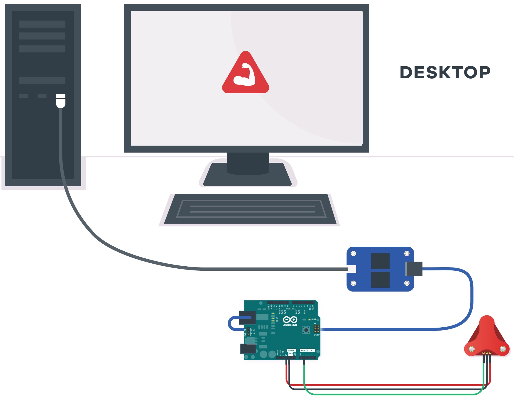
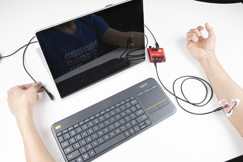
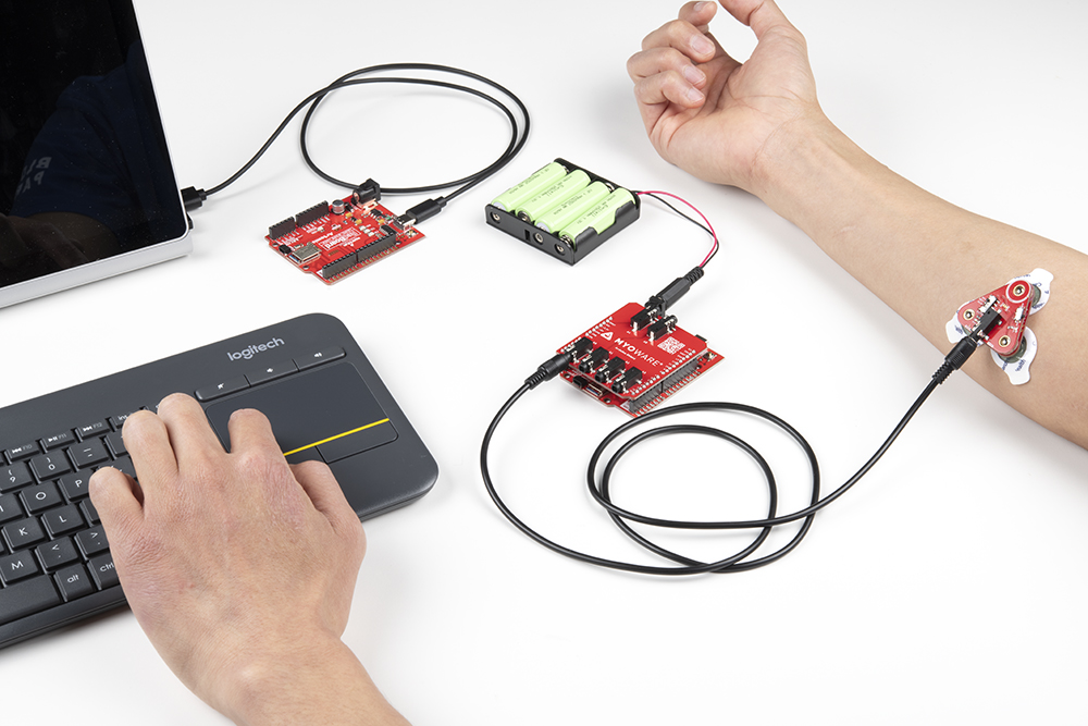
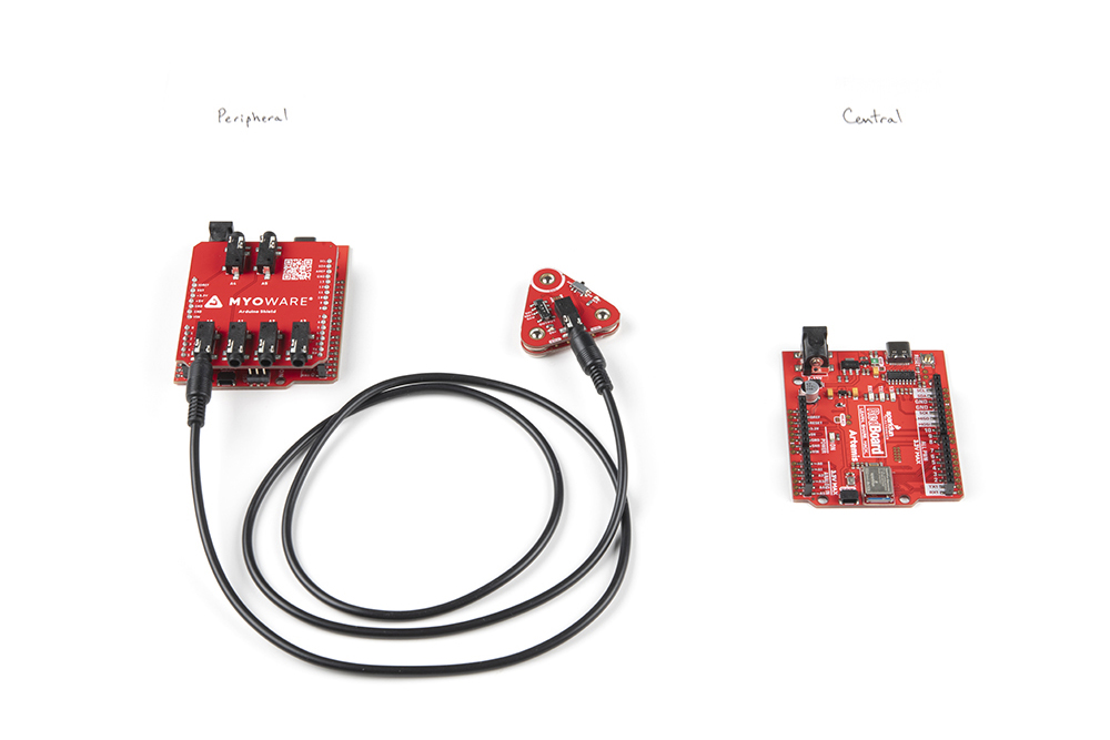
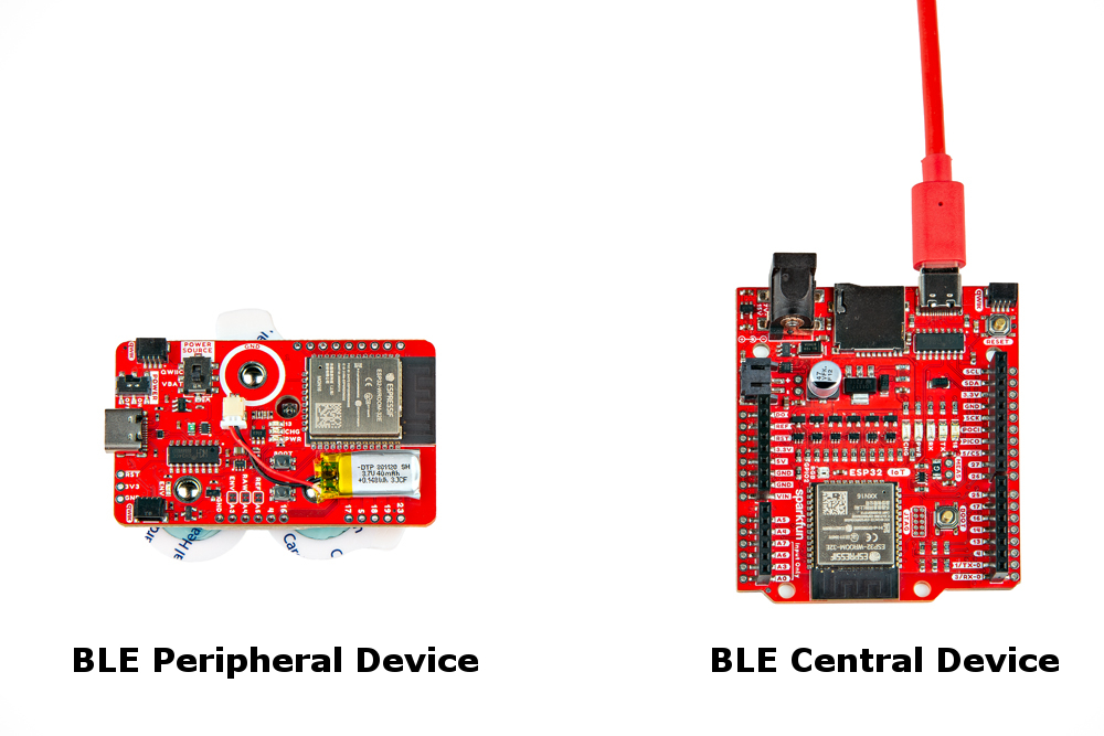
At this point, your setup should look similar to the following before attaching to the Muscle Sensor to a muscle group. To keep track of what board is the peripheral and central, try labeling the boards with a Sharpie or label maker.
Once a muscle group has been chosen, prepare the skin with alcohol wipes, remove the backs of the electrodes, and attach the stack to a muscle group. In this case, we used the forearm.
For users that are interested in connecting another Qwiic-enabled device, you will just need to insert a Qwiic cable between the two boards. You will just need to make an enclosure or find a way to mount the Qwiic-enabled device.
For muscles that require you to mount the sensor pads away from the sensor, snap the MyoWare 2.0 Cable Shield on the bottom of the MyoWare 2.0 Muscle Sensor. Then insert the sensor cable into the 3.5mm TRS connector.
Attach the EMG pads to the snap connectors. After cleaning the skin and selecting the muscle, peel and remove the backs of the electrodes to expose the adhesive. Then attach the pads to the target muscle group based on the MID, END, and REF.
| Snap Connector | TRS Pin | Electrode Pin [CAB-12970] |
|---|---|---|
| Reference [REF] | Sleeve | Black |
| End [END] | Ring | Blue |
| Middle [MID] | Tip | Red |
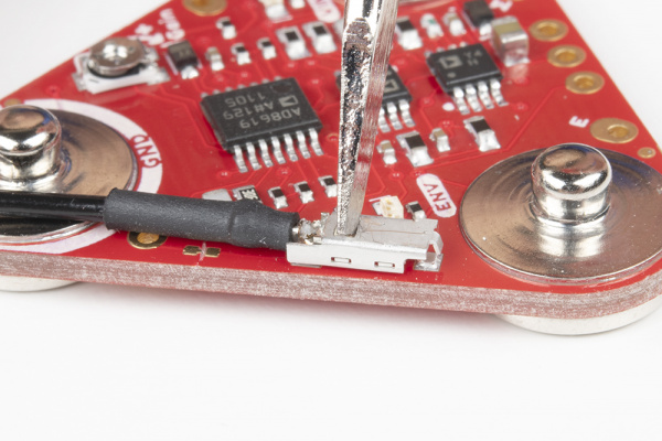
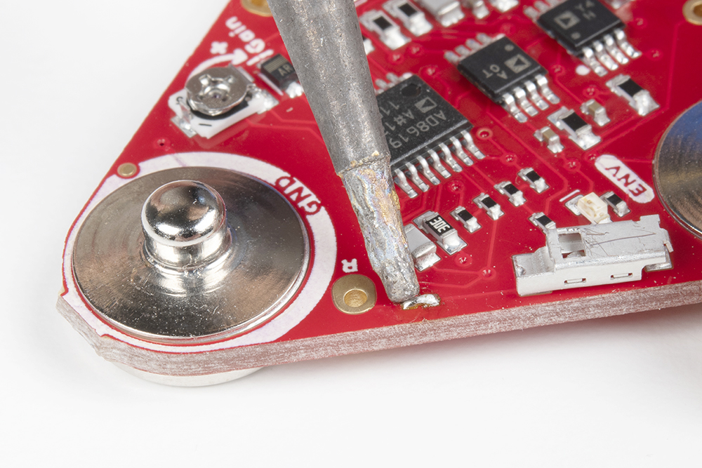
With a hobby knife, slice the reference jumper pad closest to the GND pin. There are traces near the jumper so you will need to make sure to avoid cutting traces that are adjacent to jumper pad. For more information on modifying the jumpers, check out our tutorial on working with jumper pads and PCB traces.
Then insert the reference cable into the MyoWare 2.0 Muscle Sensor, slide the pin into the housing with the tab facing away from the board.
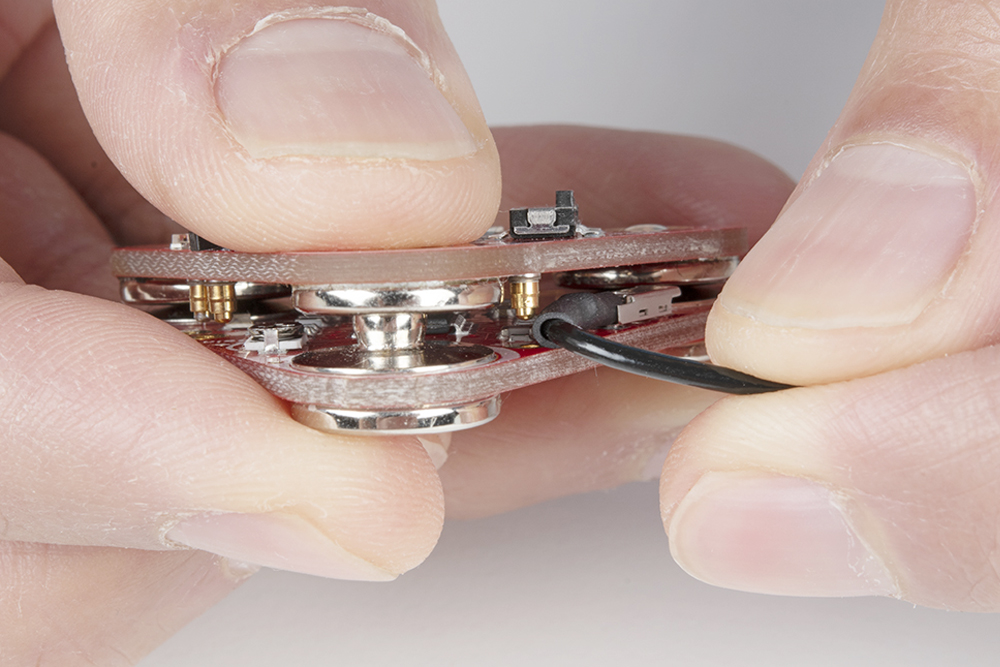
When stacking a shield on top of the MyoWare 2.0 Muscle Sensor, make sure carefully pull the cable away from the shield's snap pin.
To remove the reference cable, push the tab into the housing with the end of a flathead screwdriver and gently pull the pin out of the housing.
 |
 |
To close the jumper pad, add a small amount of solder on the jumper pad.
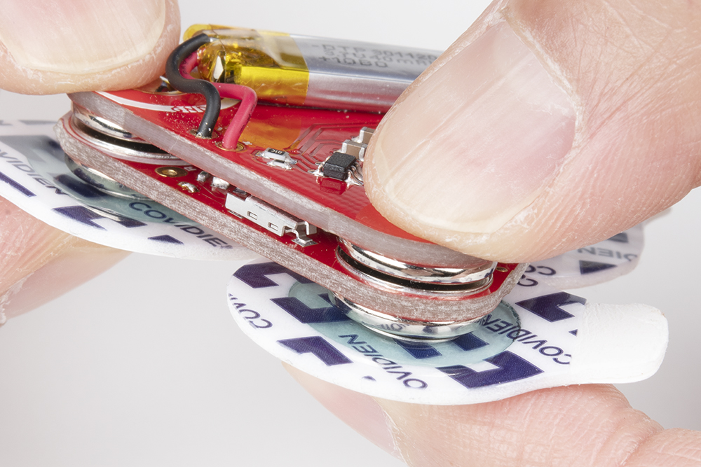
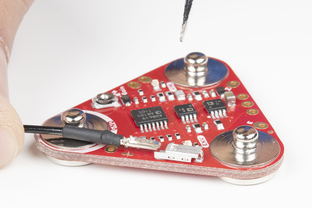
When prototyping, you will want to test out different shields or you may need to adjust the trim pot. To remove the boards, you will need a flathead screwdriver. With power off, insert the flathead between the snap connectors and ensure that there are no components in the way of the flathead. Gently slide the flathead between the snap connectors.
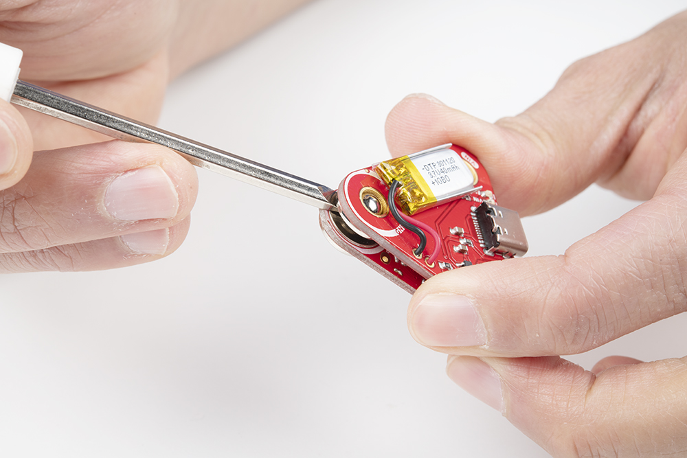
Angle the flathead against the connectors until the boards disconnect.

With one side disconnected, pull the boards away from each other so that the other two snap connectors disconnect.
To test the MyoWare 2.0 Muscle Sensor without an Arduino, you could use the MyoWare 2.0 Power Shield or the LED Shield. Both shields have a built-in battery removing the need to solder a power source to the sensor. After stacking the boards together and sticking it to a muscle group, flip the power switch to the ON position. Start flexing the muscle to see if you can light up the ENV LED on the Power Shield or the LED segments on the LED Shield!
If you are using the MyoWare 2.0 Power Shield, observe the ENV LED. The LED will be off. As you flex, the voltage from the ENV pin increases. As a result, the ENV LED will start to light up and increase in intensity as you flex the muscle. If you look closely between the stacked boards, you will also notice the ENV LED on the MyoWare 2.0 Muscle Sensor light up.
If you are using the MyoWare 2.0 LED Shield, observe the LED segments. The LED segments will be off. As you flex, the voltage from the ENV pin increases. As a result, the LED segments will start to light up. The more you flex the muscle, the more LED segments will light up. When fully flexed, all 10x LED segments will be on.

For users that cut the jumper labeled as MODE (i.e. enabling dot mode) on the MyoWare 2.0 LED Shield, you will see a different effect. A leading LED bar (i.e. "dot") will light up and traverse the segments. Any trailing LEDs behind it will be turned off instead of filling in with light. When fully flexed, one LED segment should be on.
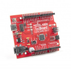
The following example uses an analog input on the RedBoard Plus with an Atmega328P to read the muscle sensor's analog signal. However, you could also use any microcontroller with the Arduino Uno R3 footprint.
If you have not already, select your Board (in this case the Arduino Uno), and associated COM port. Upload the code to the board.
language:c
/*
  MyoWare Example_01_analogRead_SINGLE
  SparkFun Electronics
  Pete Lewis
  3/24/2022
  License: This code is public domain but you buy me a beverage if you use this and we meet someday.
  This code was adapted from the MyoWare analogReadValue.ino example found here:
  https://github.com/AdvancerTechnologies/MyoWare_MuscleSensor

  This example streams the data from a single MyoWare sensor attached to ADC A0.
  Graphical representation is available using Serial Plotter (Tools > Serial Plotter menu).

  *Only run on a laptop using its battery. Do not plug in laptop charger/dock/monitor.

  *Do not touch your laptop trackpad or keyboard while the MyoWare sensor is powered.

  Hardware:
  SparkFun RedBoard Artemis (or Arduino of choice)
  USB from Artemis to Computer.
  Output from sensor connected to your Arduino pin A0

  This example code is in the public domain.
*/

void setup()
{
  Serial.begin(115200);
  while (!Serial); // optionally wait for serial terminal to open
  Serial.println("MyoWare Example_01_analogRead_SINGLE");
}

void loop()
{
  int sensorValue = analogRead(A0); // read the input on analog pin A0

  Serial.println(sensorValue); // print out the value you read

  delay(50); // to avoid overloading the serial terminal
}
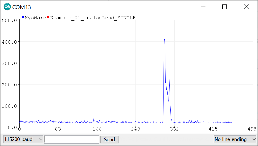
Once uploaded, open the Arduino Serial Plotter (Tools > Serial Plotter) to 115200 baud. Flip the power switch on the MyoWare 2.0 Link Shield to provide power and start flexing! You should see something similar to the output below with the envelope signal. In this case, the MyoWare 2.0 Muscle Sensor was attached to my right forearm. For those that are interested in viewing the serial output, you can also open the Arduino Serial Monitor to see the values.
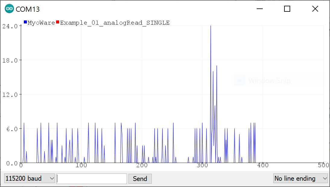
To view the Rectified or Raw signals, flip the power switch to the OFF position on the Link Shield, adjust the OUTPUT switch to either the Rectified or Raw position and then turn the power switch to the ON position. Reopen the Serial Plotter and you will see a smaller signal output when flexing your forearm.
The images below show the forearm being flexed at around 300ms when the signal increases by a value of about 22 for the rectified output and about 20 for the raw output. Note that the raw signal will be centered around a voltage offset of about +VIN/2. Make sure that the +VIN is the maximum voltage of your microcontroller's ADC to ensure that you can see the positive and negative portions of the waveform. The output shown in the graphs are values and have not been converted to voltages.
 |
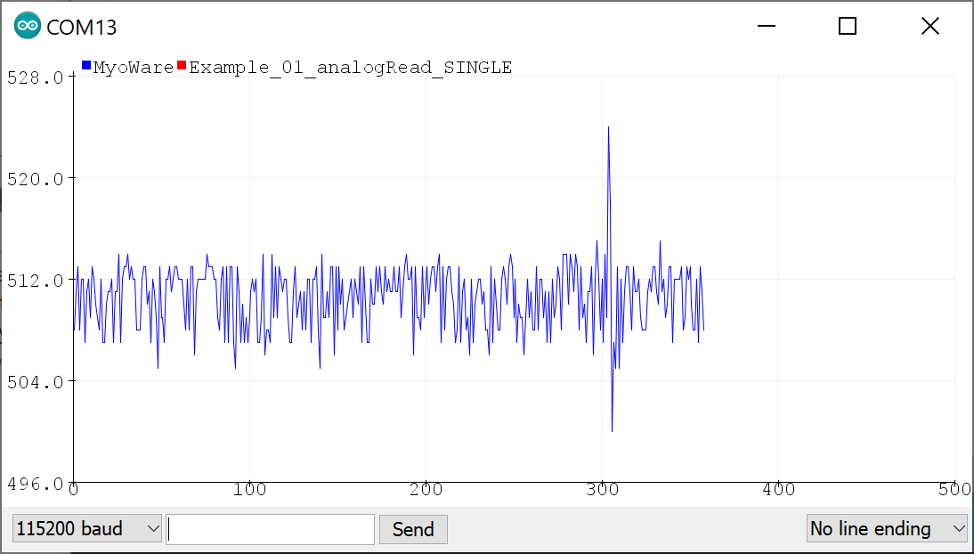 |
| Serial Plotter with Rectified Signal | Serial Plotter with Raw Signal |
The following example requires two RedBoard Artemis boards to send and receive sensor data from one muscle sensor. This is useful for users that need a clean signal or want to transmit the sensor data wirelessly.
For an explanation of how the Bluetooth peripheral and central devices works, we recommend looking at the Arduino reference language under the ArduinoBLE Library for a quick introduction.
The following example uses a RedBoard Artemis to transmit the analog reading wirelessly via Bluetooth. If you have not already, select your Board (in this case the RedBoard Artemis), and associated COM port. Copy the code below and paste into your Arduino IDE. Then upload the code to the board.
language:c
/*
MyoWare Sensor BLE Peripheral SINGLE SENSOR Example
SparkFun Electronics
Pete Lewis
3/17/2022
This example reads a single MyoWare Muscle Sensor, and then gets that data from this RedBoard Artemis
(the peripheral) to a second RedBoard Artemis (the central) over BLE.
This Artemis, aka the "BLE Peripheral", will read the sensor on A0.
It will then update the value to the "bluetooth bulletin board."
Note, in BLE, you have services, characteristics and values.
Read more about it here:
https://www.arduino.cc/reference/en/libraries/arduinoble/
Note, before it begins reading the ADC and updating the data,
It first sets up some BLE stuff:
1. sets up as a peripheral
2. sets up a service and characteristic (the data)
-Note, Services and characteristics have custom 128-bit UUID,
-These must match the UUIDs in the code on the central device.
3. advertises itself
In order for this example to work, you will need a second Artemis, and it will
need to be programmed with the provided code specific to being a central device,
looking for this specific peripheral/service/characteristic.
Note, both the service and the characteristic get unique UUIDs
(even though they are extremely close to being the same thing in this example)
The second Artemis, aka the "BLE Central," will subscribe to the first board's
characteristic, and check to see if the value has been updated. When it has been
updated, it will print the value to the serial terminal.
Hardware:
MyoWare Sensor with Link Shield snapped on top.
TRS cable from Link Shield to A0 port of Arduino Shield.
Arduino Shield pressed into RedBoard Artemis.
USB from Artemis to Computer.
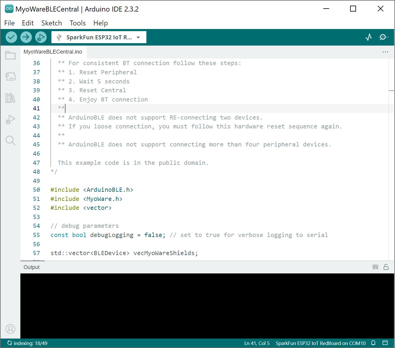
** For consistent BT connection follow these steps:
** 1. Reset Peripheral
** 2. Wait 5 seconds
** 3. Reset Central
** 4. Enjoy BT connection
**
** ArduinoBLE does not support RE-connecting two devices.
** If you loose connection, you must follow this hardware reset sequence again.
This example code is in the public domain.
*/
#include <ArduinoBLE.h>
BLEService sensorDataService("19b10000-e8f2-537e-4f6c-d104768a1214"); // BLE Service named "sensorDataService"
// BLE Data Characteristic - custom 128-bit UUID, readable, writable and subscribable by central
// Note, "BLENotify" is what makes it subscribable
BLEByteCharacteristic dataCharacteristic("19b10001-e8f2-537e-4f6c-d104768a1214", BLERead | BLEWrite | BLENotify);
const int ledPin = LED_BUILTIN; // pin to use for the LED
void setup()
{
Serial.begin(115200);
while (!Serial); // optionally wait for serial terminal to open, useful with micros that have native USB
Serial.println("MyoWare Single Sensor Example - BLE Peripheral");
pinMode(ledPin, OUTPUT); // set LED pin to output mode
if (!BLE.begin()) { // begin initialization
Serial.println("starting BLE failed!");
while (1);
}
Serial.println("BLE initiallized successfully");
BLE.setLocalName("MYOWARE1"); // set advertised local name
BLE.setAdvertisedService(sensorDataService); // set advertised service UUID
sensorDataService.addCharacteristic(dataCharacteristic); // add the characteristic to the service
BLE.addService(sensorDataService); // add service
dataCharacteristic.writeValue(0); // set the initial value for the characeristic
BLE.advertise(); // start advertising
}
void loop()
{
BLEDevice central = BLE.central(); // listen for BLE peripherals to connect
if (central) // if a central is connected to peripheral
{
Serial.print("Connected to central: ");
Serial.println(central.address()); // print the central's MAC address
Serial.println("Reading Sensor and writing BLE characteristic values now...");
// while the central is still connected to peripheral:
while (central.connected())
{
int val_int = analogRead(A0); // Read the sensor attached to Analog Pin A0
byte val_byte = map(val_int, 0, 1023, 0, 255); // map the int to a byte
delay(10);
dataCharacteristic.writeValue(val_byte); // "post" to "BLE bulletin board"
// Note, because our second Artemis in this example (the central) is subscribed to this characteristic,
// it can simply call Characteristic.valueUpdated() to see if it has been updated.
// valueUpdated() will return True if updated, or false if no update has happened.
// If it has been updated, the central Artemis can read the latest value using Characteristic.readValue();
}
Serial.print(F("Disconnected from central: ")); // when the central disconnects, print it out
Serial.println(central.address());
}
}
The following example uses a RedBoard Artemis to receive the analog reading from the peripheral RedBoard Artemis wirelessly via Bluetooth. If you have not already, select your Board (in this case the RedBoard Artemis), and associated COM port. Copy the code below and paste into your Arduino IDE. Then upload the code to the board.
language:c
/*
  MyoWare Receiver BLE Central SINGLE SENSOR Example
  SparkFun Electronics
  Pete Lewis
  3/17/2022

  This example sets up a SparkFun RedBoard Artemis as a BLE central device,
  Then, it connects to a second Artemis peripheral device that is reading a single MyoWare
  Muscle sensor. It then streams the data on the Serial Terminal.

  Note, in BLE, you have services, characteristics and values.
  Read more about it here:

  https://www.arduino.cc/reference/en/libraries/arduinoble/

  Note, before it begins checking the data and printing it,
  It first sets up some BLE stuff:
    1. sets up as a central
    2. scans for any peripherals
    3. Connects to the device named "MYOWARE1"
    4. Subscribes MYOWARE1's data characteristic

  In order for this example to work, you will need a second Artemis, and it will
  need to be programmed with the provided code specific to being a peripheral device,
  and advertising as MYOWARE1 with the specific characteristic UUID.

  Note, both the service and the characteristic get unique UUIDs
  (even though they are extremely close to being the same thing in this example)

  This Artemis, aka the "BLE Central," will subscribe to the peripheral board's
  characteristic, and check to see if the value has been updated. When it has been
  updated, it will print the value to the serial terminal.

  Hardware:
  SparkFun RedBoard Artemis
  USB from Artemis to Computer.

  ** For consistent BT connection follow these steps:
  ** 1. Reset Peripheral
  ** 2. Wait 5 seconds
  ** 3. Reset Central
  ** 4. Enjoy BT connection
  **
  ** ArduinoBLE does not support RE-connecting two devices.
  ** If you loose connection, you must follow this hardware reset sequence again.

  This example code is in the public domain.
*/

#include <ArduinoBLE.h>

void setup()
{
  Serial.begin(115200);
  while (!Serial); // optionally wait for serial terminal to open, useful with micros that have native USB
  Serial.println("MyoWare Single Sensor Example - BLE Central");

  if (!BLE.begin()) // initialize the BLE hardware
  {
    Serial.println("starting BLE failed!");
    while (1);
  }
  Serial.println("BLE initiallized successfully");

  BLE.scanForUuid("19b10000-e8f2-537e-4f6c-d104768a1214"); // start scanning for peripherals
}

void loop()
{
  BLEDevice peripheral = BLE.available(); // check if a peripheral has been discovered

  if (peripheral) // discovered a peripheral, print out its info
  {
    Serial.print("Found ");
    Serial.print(peripheral.address());
    Serial.print(" '");
    Serial.print(peripheral.localName());
    Serial.print("' ");
    Serial.print(peripheral.advertisedServiceUuid());
    Serial.println();

    if (peripheral.localName() != "MYOWARE1")
    {
      return;
    }

    BLE.stopScan();

    checkUpdate(peripheral);

    Serial.println("Starting to scan for new peripherals again...");
    BLE.scanForUuid("19b10000-e8f2-537e-4f6c-d104768a1214"); // peripheral disconnected, scan again
    Serial.println("Scan has begun...");
  }
}

// Connect to peripheral
// Then continue to check if the data has been updated,
// If so, print it to terminal
void checkUpdate(BLEDevice peripheral)
{
  Serial.println("Connecting ..."); // connect to the peripheral

  if (peripheral.connect())
  {
    Serial.println("Connected");
  } else {
    Serial.println("Failed to connect!");
    return;
  }

  Serial.println("Discovering attributes ..."); // discover peripheral attributes
  if (peripheral.discoverAttributes())
  {
    Serial.println("Attributes discovered");
  } else {
    Serial.println("Attribute discovery failed!");
    peripheral.disconnect();
    return;
  }

  // retrieve the data characteristic
  BLECharacteristic dataCharacteristic = peripheral.characteristic("19b10001-e8f2-537e-4f6c-d104768a1214");

  if (!dataCharacteristic)
  {
    Serial.println("Peripheral does not have that characteristic!");
    peripheral.disconnect();
    return;
  } else if (!dataCharacteristic.canWrite())
  {
    Serial.println("Peripheral does not have a writable characteristic!");
    peripheral.disconnect();
    return;
  } else if (!dataCharacteristic.canRead())
  {
    Serial.println("Peripheral does not have a readable characteristic!");
    peripheral.disconnect();
    return;
  } else if (!dataCharacteristic.canSubscribe())
  {
    Serial.println("Characteristic is not subscribable!");
    peripheral.disconnect();
    return;
  } else if (!dataCharacteristic.subscribe())
  {
    Serial.println("subscription failed!");
    peripheral.disconnect();
    return;
  }

  while (peripheral.connected()) // while the peripheral is connected
  {
    if (dataCharacteristic.valueUpdated()) // Check to see if the value of the characteristic has been updated
    {
      byte received_val = 0;
      dataCharacteristic.readValue(received_val); // note, readValue returns nothing, and needs the variable to be passed by reference
      Serial.println(received_val);
    }
    delay(1);
  }
  Serial.println("Peripheral disconnected");
}
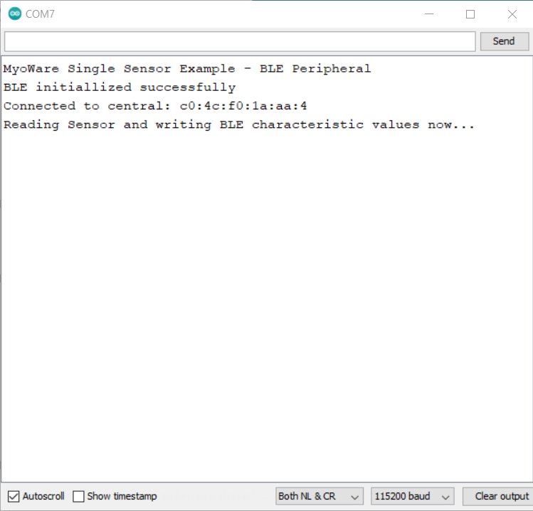
With two instances of the Arduino IDE open with a COM port selected for each respective board, you should see the following output in the Serial Monitor set to 115200 baud. If the Bluetooth fails to connect, try pushing the reset button on the Peripheral first, wait about 5 seconds, then hit the reset button on the Central. Once connected, the muscle sensor readings will be transmitted wirelessly to the central. Try flexing your arm to see if you can see the values increase.
 |
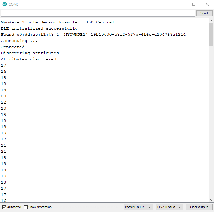 |
| Debug Output from Peripheral Device | Debug Output from Central Device |
For users looking for a graphical view of the output, close the Arduino Serial Monitor for the Bluetooth set as the Central device (i.e. the RedBoard Artemis receiving the sensor data). Then open the Arduino Serial Plotter. You should see something similar to the output below. In this case, we flexed our forearm muscle causing the values to increase. Relaxing the muscle caused the values to decrease.
Looking for more examples? Try checking out the GitHub Repository to use multiple analog channels via BLE! There's also a project example that connects to the Tsunami Super WAV Trigger (Qwiic) and speaker.
Using a different microcontroller? You can use the sensor with MakeCode and a micro:bit by opening the MakeCode_Examples folder. You can even check out the MicroPython example with the RP2040 located in the Python_Examples folder.
Advancer Technologies has written an Arduino Library for the MyoWare 2.0 Muscle Sensor and the ecosystem! This library helps users interact with the MyoWare 2.0 Muscle Sensor, MyoWare 2.0 Wireless Shield, and more. The MyoWare Arduino Library can be downloaded with the Arduino Library Manager by searching 'MyoWare Arduino Library' or you can grab the zip here from the GitHub repository to manually install:
The following example requires the Wireless Shield and a BLE module to send and receive sensor data from one muscle sensor. This is useful for users that need a clean signal or want to transmit the sensor data wirelessly.
For an explanation of how Bluetooth peripheral and central devices work, we recommend looking at the Arduino reference language under the ArduinoBLE Library for a quick introduction.
This example is for those that are modifying the firmware on the MyoWare 2.0 Wireless Shield. This is useful if you have more than one peripheral device. The example code uses a MyoWare 2.0 Wireless Shield to transmit the analog reading wirelessly via Bluetooth. Connect the MyoWare 2.0 Wireless Shield to your Computer if you have not already. Select the Power Source and flip the power switch to the ON position.
This particular example uses code from the MyoWare Arduino Library which is located in a different GitHub repository. With the library installed, head to the menu and select the following: File > Examples > MyoWare Arduino Library > MyoWareBLEPeripheral.
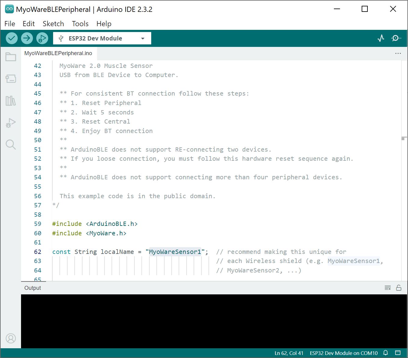
By default, the Wireless Shield includes firmware to act as a peripheral device. For users connecting more than one Wireless Shield to your central device, we recommend changing the BLE peripheral device name with a unique name. For this example, you would change the number in the following line of code in the MyoWareBLEPeripheral.ino for each additional peripheral device:
language:c
const String localName = "MyoWareSensor1";  // recommend making this unique for
                                            // each Wireless shield (e.g. MyoWareSensor1,
                                            // MyoWareSensor2, ...)</code></pre>
The second Wireless Shield would need to have the localname changed to MyoWareSensor2.
language:c
const String localName = "MyoWareSensor2";  // recommend making this unique for
                                                // each Wireless shield (e.g. MyoWareSensor1,
                                                // MyoWareSensor2, ...)
If you have not already, select your Board and associated COM port (in this case, the ESP32 Dev Module on COM10). Then upload the modified code to the board.
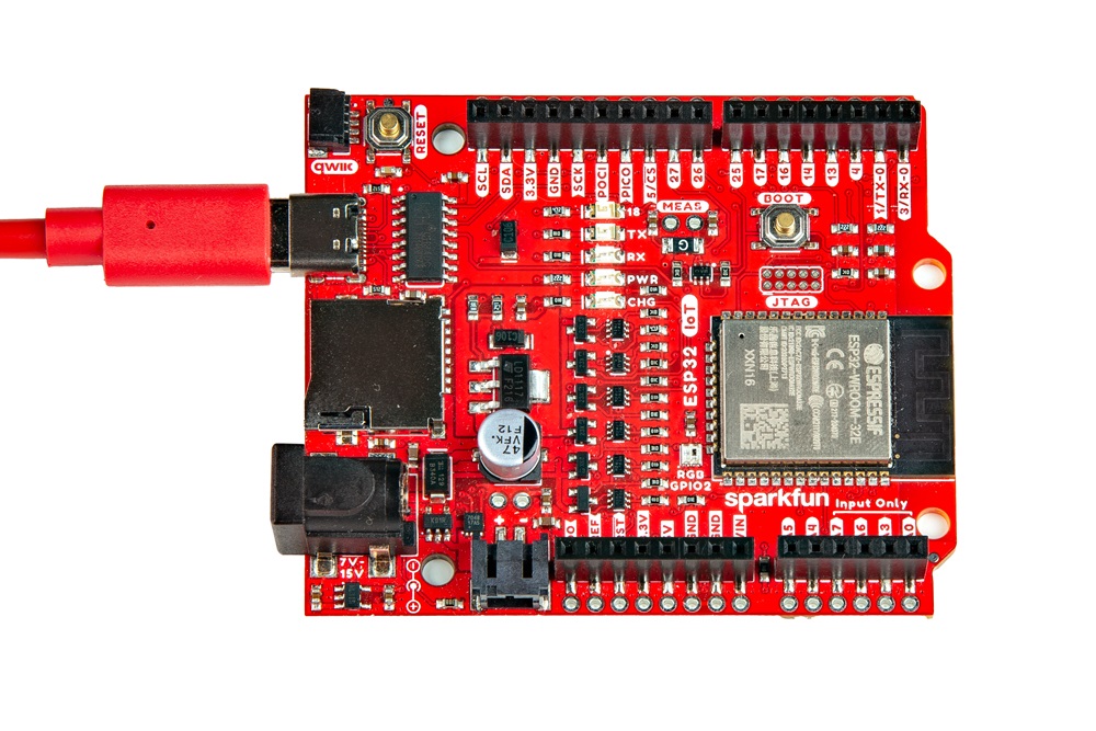
The following example uses an IoT RedBoard - ESP32 to receive the analog reading from the peripheral MyoWare 2.0 Wireless Shield. Of course, users can also use other Arduino boards that support Arduino BLE. Connect the IoT RedBoard - ESP32 to your computer if you have not already.
This particular example uses code from the MyoWare Arduino Library as well. With the library installed, head to the menu and select the following: File > Examples > MyoWare Arduino Library > MyoWareBLECentral .
If you have not already, select your Board and associated COM port (in this case, the SparkFun ESP32 IoT RedBoard on COM10). Then upload the code to the board.
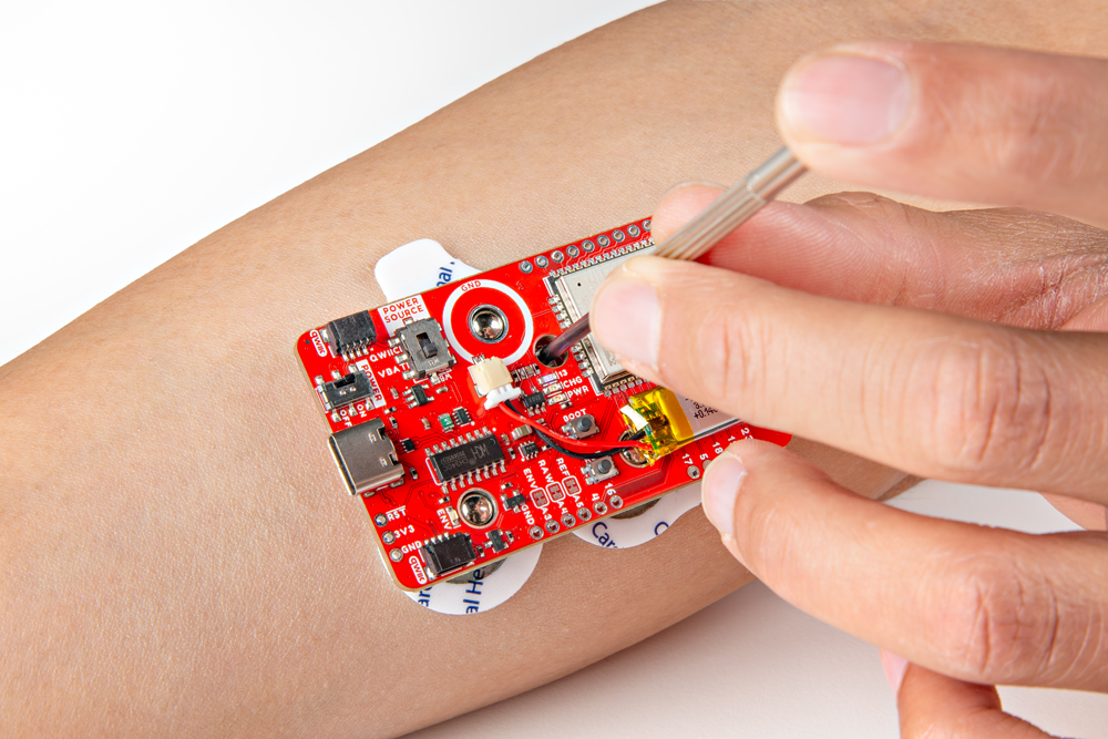
Choose a target muscle group, prepare the skin with alcohol wipes, remove the backs of the electrodes, and attach the stack to a muscle group. In this case, we used the forearm. Turn the POWER switch to the ON position.
With the IoT RedBoard - ESP32 still connected to your computer, open Arduino Serial Monitor set at 115200 baud. If the Bluetooth fails to connect, try pushing the reset button on the Peripheral first, wait about 5 seconds, then hit the reset button on the Central.
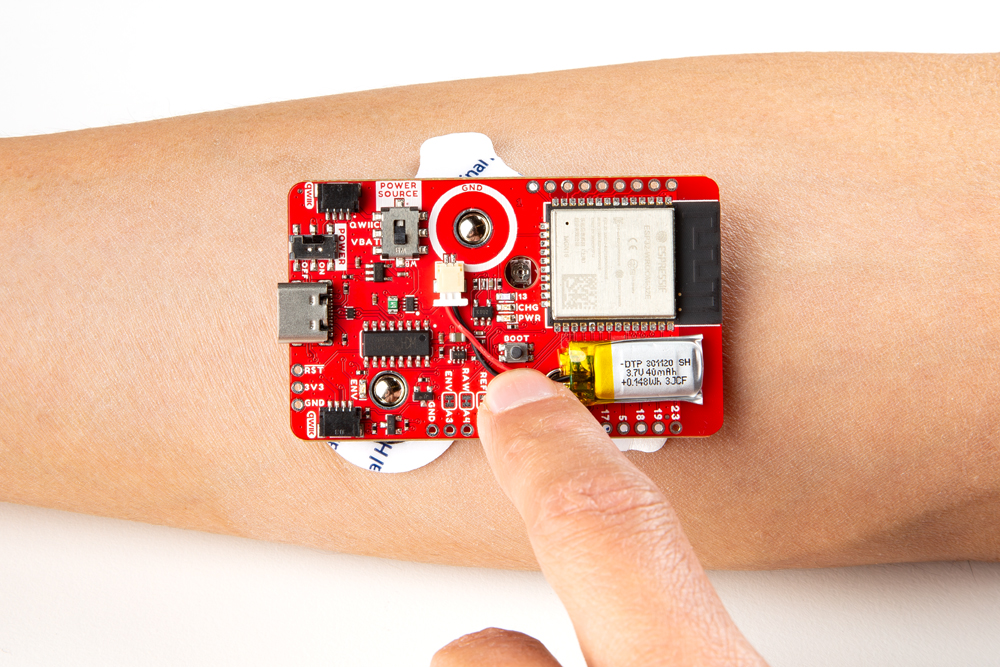 |
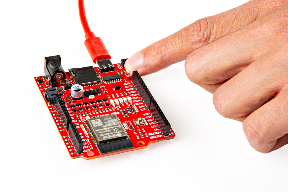 |
| Reset MyoWare 2.0 Wireless Sensor | Reset IoT RedBoard - ESP32 |
Once connected, the muscle sensor readings will be transmitted wirelessly to the central device. Try flexing your muscle to see if you can see the values increase. Below are the readings in the Serial Monitor and Serial Plotter while flexing and then relaxing a forearm muscle.
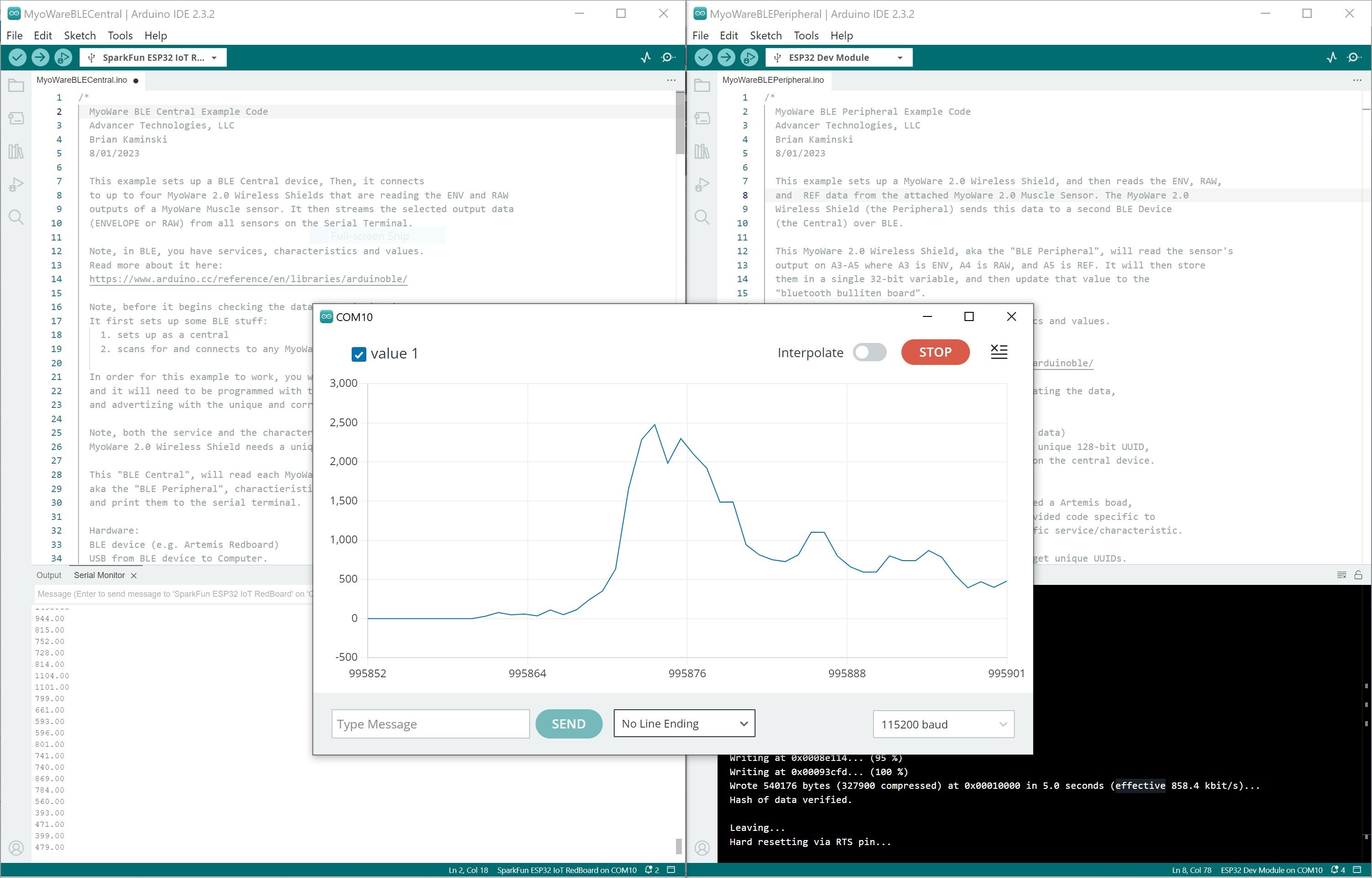
For users looking for a graphical view of the output, close the Arduino Serial Monitor for the Bluetooth set as the Central device (i.e the IoT RedBoard - ESP32 receiving the sensor data). Then open the Arduino Serial Plotter. You should see something similar to the output as shown above. In this case, we flexed our forearm muscle causing the values to increase. Relaxing the muscle caused the values to decrease.
Looking for more examples? Try checking out the other examples within the MyoWare Arduino Library!
For your convenience, the following troubleshooting tips for the MyoWare 2.0 Muscle Sensor are provided from the MyoWare 2.0 Quick Start Guide.
Now that you've successfully got your MyoWare 2.0 Muscle Sensor up and running, it's time to incorporate it into your own project! Try embedding the sensor in a prosthetic arm, controlling a servo to grip something, Halloween costume, video game, or turning on LEDs in a dance performance! For more information, check out the resources below:
[1] Note: This product is patent protected. To prevent counterfeit boards, the Eagle design files and GitHub hardware repository are not shared for boards in the MyoWare 2.0 ecosystem.
Need some inspiration for your next project? Check out some of these related tutorials tagged with biometrics.
learn.sparkfun.com | CC BY-SA 3.0 | SparkFun Electronics | Niwot, Colorado