Getting Started with MicroPython and the SparkFun Inventor's Kit for micro:bit
 LightningHawk
 Experiment 8: Using a Servo Motor
Introduction
This experiment is your introduction to the servo motor, which is a smart motor that you can tell to rotate to a specific angular location. You will program it to rotate to a series of locations, then sweep across its full range of motion, and then repeat.
Parts Needed
You will need the following parts:
- 1x Breadboard
- 1x micro:bit
- 1x micro:bit Breakout with Headers
- 1x micro-B USB Cable
- 1x Servo
- 3x Jumper Wires
Didn't Get the SIK for micro:bit?
If you are conducting this experiment and didn't get the Inventor's Kit, we suggest using these parts:


Suggested Reading
Before continuing with this experiment, we recommend you be familiar with the concepts in the following tutorial:
Pulse Width Modulation
Hobby Servo Tutorial
Introducing the Servo Motor

Unlike the action of most motors that continuously rotate, a servo motor can rotate to and hold a specific angle until it is told to rotate to a different angle. You can control the angle of the servo by sending it a PWM (Pulse Width Modulation) pulse train; the PWM signal is mapped to a specific angle from 0 to 180 degrees.
Inside of the servo there is a gearbox connected to a motor that drives the shaft. There is also a potentiometer that gives feedback on the rotational position of the servo, which is then compared to the incoming PWM signal. The servo adjusts accordingly to match the two signals.
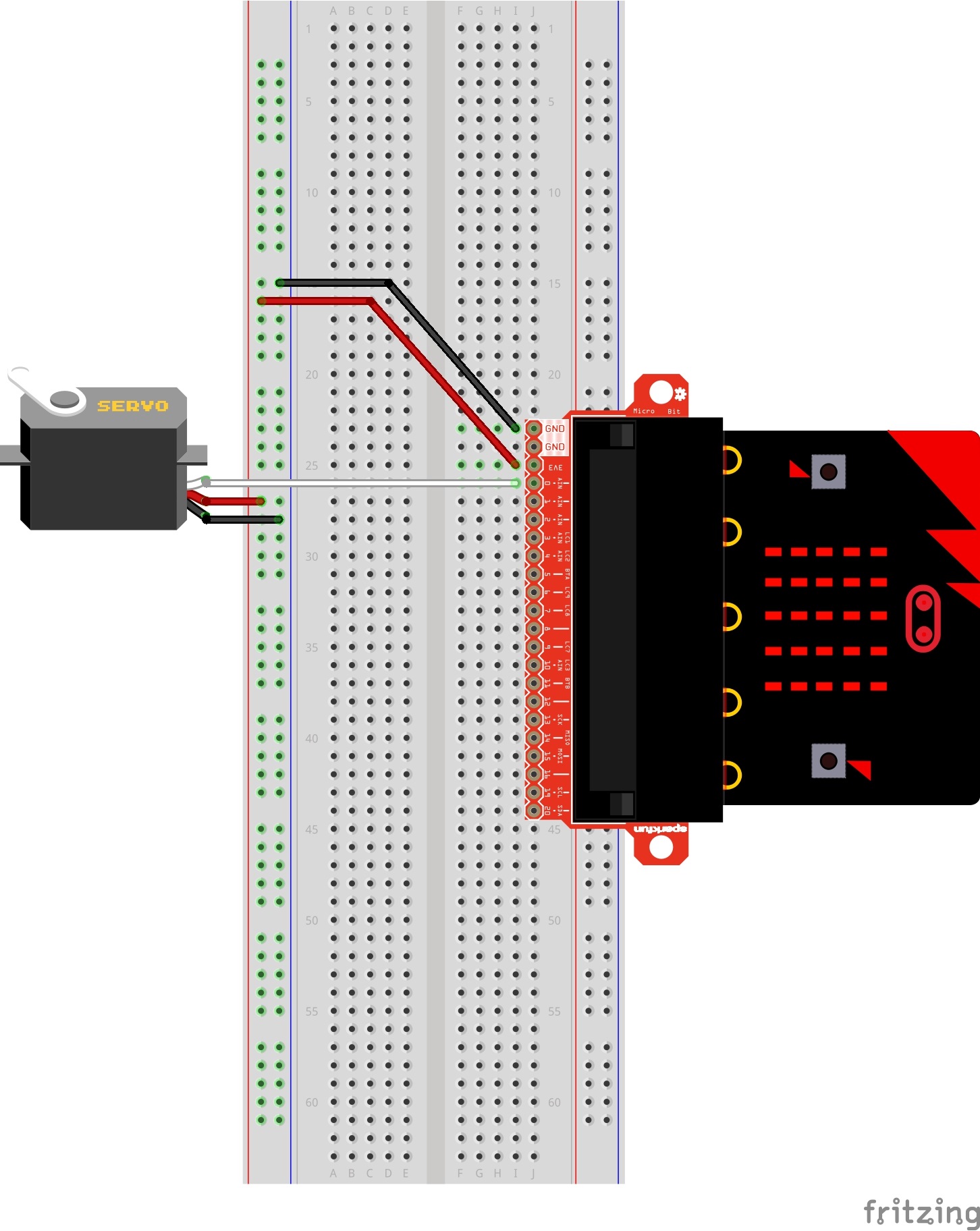
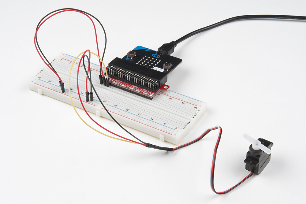
In this experiment, the servo is powered through 3.3 volts on the red wire and ground on the black wire; the white wire is connected to pin P0.
Hardware Hookup
Ready to start hooking everything up? Check out the wiring diagram below to see how everything is connected.
| Polarized Components | Pay special attention to the component’s markings indicating how to place it on the breadboard. Polarized components can only be connected to a circuit in one direction. |
Connect 3x jumper wires to the female 3-pin header on the servo. This will make it easier to breadboard the servo.
Wiring Diagram for the Experiment
Run Your Script
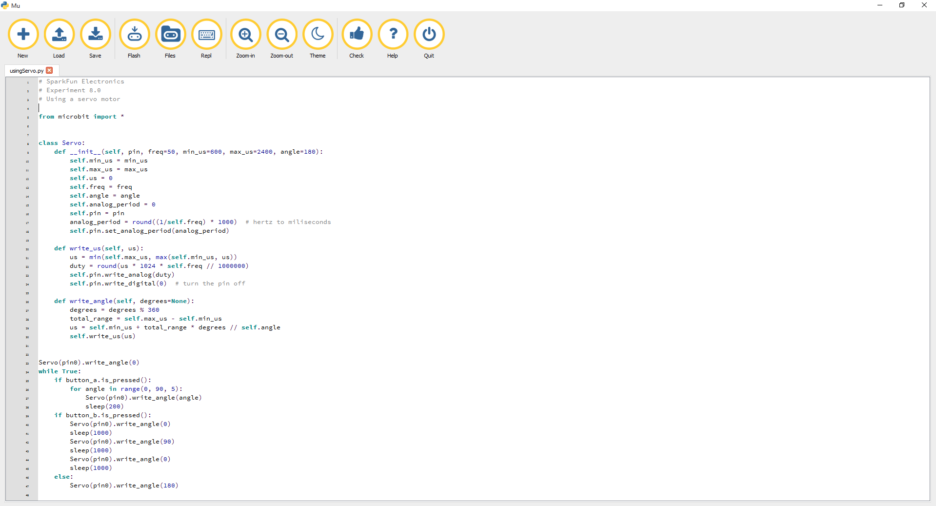
Let's drive a servo. Type (or copy) the program into your Mu editor, or download all the programs from this GitHub Repository and open the Ex8_usingServo.py program. Save it, then click the Flash icon to program your micro:bit.
language:python
# SparkFun Electronics
# Experiment 8.0
# Using a servo motor

from microbit import *


class Servo:
    def __init__(self, pin, freq=50, min_us=600, max_us=2400, angle=180):
        self.min_us = min_us
        self.max_us = max_us
        self.us = 0
        self.freq = freq
        self.angle = angle
        self.analog_period = 0
        self.pin = pin
        analog_period = round((1/self.freq) * 1000)  # hertz to miliseconds
        self.pin.set_analog_period(analog_period)

    def write_us(self, us):
        us = min(self.max_us, max(self.min_us, us))
        duty = round(us * 1024 * self.freq // 1000000)
        self.pin.write_analog(duty)
        sleep(100)
        self.pin.write_digital(0)  # turn the pin off

    def write_angle(self, degrees=None):
        if degrees is None:
            degrees = math.degrees(radians)
        degrees = degrees % 360
        total_range = self.max_us - self.min_us
        us = self.min_us + total_range * degrees // self.angle
        self.write_us(us)


Servo(pin0).write_angle(0)
while True:
    if button_a.is_pressed():
        for angle in range(0, 90, 5):
            Servo(pin0).write_angle(angle)
            sleep(200)
    if button_b.is_pressed():
        Servo(pin0).write_angle(0)
        sleep(1000)
        Servo(pin0).write_angle(90)
        sleep(1000)
        Servo(pin0).write_angle(0)
        sleep(1000)
    else:
        Servo(pin0).write_angle(180)
Code to Note
One of the major drawbacks to using MicroPython with the micro:bit is that you can't import third-party modules in Mu. Or at least, we haven't had any luck flashing two Python files in the editor to the micro:bit. This code seems long because we had to paste the Servo Class code into our script for ease of use [1]. Ignoring the Servo Class code, let's look at what's happening inside the forever loop.
while True: is executed as explained earlier. The other option is to save the module as servo.py, place it in the root directory of your computer, and then import it using the following code:# from servo.py import the Servo class
from servo import Servorange
The range function generates a list of numbers. In this experiment we are generating a list from 0--90 that increases by 5.
Servo(pin0).write_angle()
The Servo Class is called in statement with pin 0 as its argument. The .write_angle() function is how the servo is moved --- by the number specified in the parentheses mapped to degrees on the servo motor.
What You Should See
When powered up you should see the servo move to a single location (0 degrees) and then start to sweep to 180 degrees back and forth until you turn it off or tell it to go to a different angle.
Troubleshooting
Servo Not Twisting
Even with colored wires, it is still shockingly easy to plug a servo in backward. This might be the case.
Still Not Working
A mistake we made a time or two was simply forgetting to connect the power (red and black wires) to 3.3 volts and ground (GND).