ESP32 Thing Hookup Guide
 jimblom
 Introduction
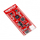
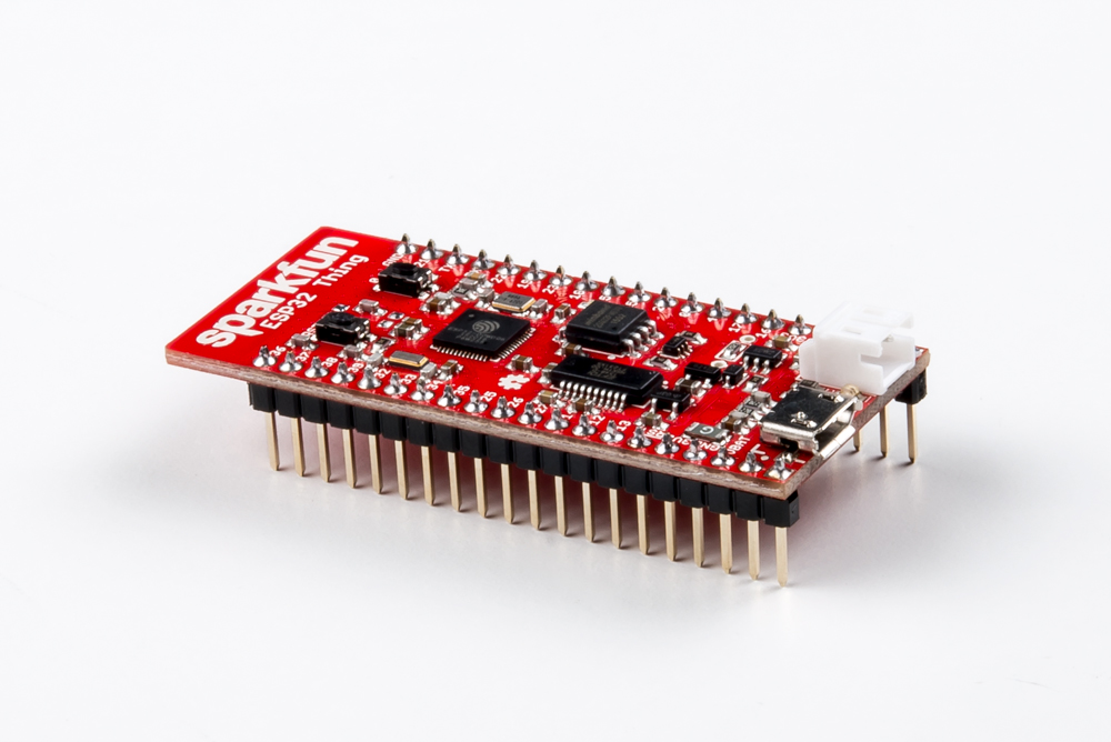
The SparkFun ESP32 Thing is a comprehensive development platform for Espressif's ESP32, their super-charged version of the popular ESP8266. Like the 8266, the ESP32 is a WiFi-compatible microcontroller but adds nearly 30 I/O pins. The ESP32’s power and versatility will make it the foundation of IoT and connected projects for many years to come.

The SparkFun ESP32 Thing equips the ESP32 with everything necessary to program, run, and develop on the wonderchip. In addition to the WiFi SoC, the Thing includes an FTDI FT231x, which converts USB to serial, and allows your computer to program and communicate with the microcontroller. It also features a lithium-polymer (LiPo) battery charger, so your ESP32 project can be truly wireless. Additionally, the board includes a handful of LEDs and buttons to aid in your development.
Covered In This Tutorial
This hookup guide serves as a primer on all things ESP32 Thing. It documents hardware features of the board, including a handful of assembly tips. Then it will delve into firmware development -- including demonstrating how to add ESP32 support to the popular Arduino IDE.
The tutorial is broken up into a handful of sections, which you can navigate through using the menu on the right. Those sections include:
- Hardware Overview -- An examination of the ESP32 Thing's hardware layout and features, including an introduction to the ESP32's I/O capabilities.
- Assembly Tips -- Quick soldering tips and tricks.
- Installing via Arduino IDE Boards Manager -- How to add ESP32 support using the Arduino Boards Manager.
- Installing the ESP32 Arduino Core -- How to add ESP32 support to your computer's Arduino development environment.
- Arduino Example: Blink -- Verify that your ESP32 Thing and Arduino board definitions work with the classic blink sketch.
- Arduino Example: WiFi -- Connect your ESP32 to a local WiFi network, and start IoT'ing.
- Using the Arduino Add-on -- Tips to help you get started creating Arduino sketches of your own.
The Arduino board definitions for the ESP32 are still a work in progress. There are a handful of peripherals and features that have yet to be implemented, including:
* Analog Input (
analogRead([pin]))* Analog Ouptut (
analogWrite([pin], [value]))* WiFi Server and WiFI UDP
* Real-Time Clock
* Touch-controller interface
These peripherals are available (if, also, still in their infancy) in the IoT Development Framework for the ESP32. If your application requires analog input, RTC, or any of the features above, consider giving the ESP-IDF a try!
Bill of Materials
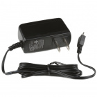
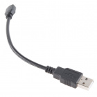
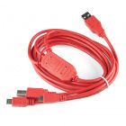
The ESP32 Thing includes almost everything you'll need to begin using and programming the WiFi/BT SoC. In fact, the only required extra is a Micro-B USB Cable. The ESP32 Thing's USB interface can be used to both power and program the chip. Once you're done programming the chip, a 5V Micro-B USB Wall Adapter can be used to power the board.

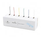
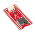
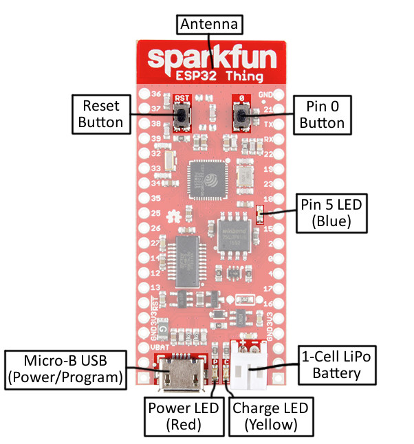
As an alternative power source, the ESP32 Thing includes support for single-cell lithium-polymer (LiPo) batteries, which plug into the board's white 2-pin JST connector. LiPo's are perfect for projects on-the-go, or those that just need a little extra umph. The board includes a LiPo charger -- the rechargeable batteries can be juiced back up by plugging the Thing into a 5V USB source.


Finally, to connect the ESP32's 28 I/O pins to external components, you'll need to do some soldering. Soldering tools, including an iron and solder, are a must for any electronics workbench. And either headers or wire are our recommended mate for soldering into the Thing's pins.


Suggested Reading
It may look intimidating, but the ESP32 Thing -- especially when you take advantage of its Arduino compatibility -- is a perfect IoT foundation for electronics users of all experience levels. There are, however, a few concepts you should be familiar with before venturing further into this tutorial. If any of the concepts below sound foreign to you, consider reading through that tutorial first:
How to Solder: Through-Hole Soldering
Serial Communication
What is an Arduino?
Looking to get hands-on with ESP32?
We've got you covered!
Hardware Overview
Espressif's ESP32 is one of the most unique microcontrollers on the market. Its laundry list of features include:
- Dual-core Tensilica LX6 microprocessor
- Up to 240MHz clock frequency
- 520kB internal SRAM
- Integrated 802.11 BGN WiFi transceiver
- 2.2 to 3.6V operating range
- 2.5 µA sleep current under hibernation
- 32 GPIO
- 10-electrode capacitive touch support
- Hardware accelerated encryption (AES, SHA2, ECC, RSA-4096)
The ESP32 Thing is designed to surround the ESP32 with everything necessary to run and program the microcontroller, plus a few extra goodies to take advantage of the chip's unique features.
Peripherals and I/O
The ESP32 features your standard fare of hardware peripherals, including:
- 18 analog-to-digital converter (ADC) channels
- 3 SPI interfaces
- 3 UART interfaces
- Two I2C interfaces
- 16 PWM outputs
- 2 digital-to-analog converters (DAC)
- Two I2S interfaces
And, thanks to the chip's pin multiplexing feature, those peripherals can be connected to just about any of the 28 broken out I/O pins. That means you decide which pins are RX, TX, MISO, MOSI, SCLK, SDA, SCL, etc.
There are, however, a few hardware features -- namely the ADC and DAC -- which are assigned static pins. The graphical reference below helps demonstrate where you can find those peripherals (click to embiggen!).
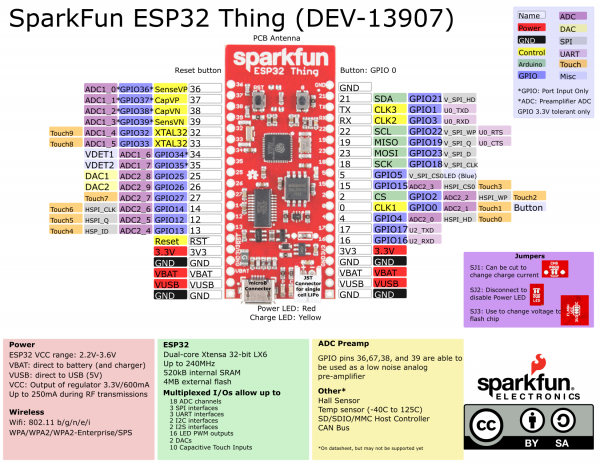
One I2C, two of the UART interfaces, and one of the SPI interfaces can be assigned to any pin your project requires.
Input Only Pins: 34-39
Pins 34, 35, 36, 37, 38 and 39 cannot be configured as outputs, but they can be used as either digital inputs, analog inputs, or for other unique purposes. Also note that they do not have internal pull-up or pull-down resistors, like the other I/O pins.
GPIO pins 36-39 are an integral part of the ultra low noise pre-amplifier for the ADC – they are wired up to 270pF capacitors, which help to configure the sampling time and noise of the pre-amp.
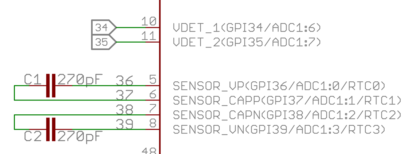
From the ESP32 Thing Schematic: GPIO 36-39 are tied together with caps. Those and pins 34 and 35 are input only!
Powering the ESP32 Thing
The two main power inputs to the ESP32 Thing are USB and a single-cell lithium-polymer (LiPo) battery. If both USB and the LiPo are plugged into the board, the onboard charge controller will charge the LiPo battery at a rate of up to 500mA.
The ESP32's operating voltage range is 2.2 to 3.6V. Under normal operation the ESP32 Thing will power the chip at 3.3V. The I/O pins are not 5V-tolerant! If you interface the board with 5V (or higher) components, you'll need to do some level shifting.
The 3.3V regulator on the ESP32 Thing can reliably supply up to 600mA, which should be more than enough overhead for most projects. The ESP32 can pull as much as 250mA during RF transmissions, but we've generally measured it to consume around 150mA -- even while actively transmitting over WiFi. The output of the regulator is also broken out to the sides of the board -- the pins labeled "3V3." These pins can be used to supply external components.
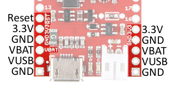
In addition to USB and battery connectors, the VBAT, and VUSB pins are all broken out to both sides of the board. These pins can be used as an alternative supply input to the Thing. The maximum, allowable voltage input to VUSB is 6V, and VBAT should not be connected to anything other than a LiPo battery. Alternatively, if you have a regulated voltage source between 2.2V and 3.6V, the "3V3" lines can be used to directly supply the ESP32 and its peripherals.
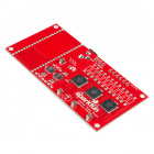
Board Dimensions
The board is 2.32"x1.00".

Assembly Tips
The ESP32 Thing ships without anything soldered into the header pins -- ensuring that you can mold the board to best fit your project. To use the chip's pins you'll need to solder something to the I/O and power rail vias broken out to either side of the board.
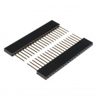
What you solder to the ESP32 Thing's I/O pins is completely up to you. The header rows are breadboard-compatible, so you may want to solder male headers in. (Mildly satisfying: the ESP32 Thing's pair of 20-pin headers means you can get the most out of our 40-pin header strips.)
Then plug it into the breadboard, hanging the USB and LiPo connectors off the end, and start wiring!
Alternatively, female headers (you may need two separate strips to solder all 40 pins), right-angle headers, or stranded wire are all good options, depending on your project's needs.
Installing via Arduino IDE Boards Manager
Good news! Espressif has added support for the Arduino Boards Manager and by installing this way, you get the benefit of a slew of great built-in examples. Instructions for installing via the board manager can be found at espressif's Arduino-ESP32 Read the Docs.
For more information on installing boards via the Arduino Board Manager, check out the Installing Board Definitions in the Arduino IDE tutorial.
Installing Board Definitions in the Arduino IDE
September 9, 2020
If you are familiar with installing boards via the Arduino IDE Boards Manager, the url to add is:
language:bash
https://raw.githubusercontent.com/espressif/arduino-esp32/gh-pages/package_esp32_index.json
https://dl.espressif.com/dl/package_esp32_index.json. Make sure to update the link in your Board Manager to the latest json file from GitHub as linked above.
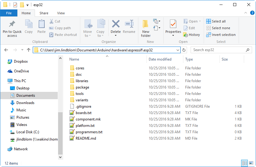
To remove previous arduino core installs for the esp32, start by finding your .../Arduino/hardware folder. This can be located by looking at your Sketchbook location under File > Preferences.

Go to this location in your finder and delete the esp32 folder.

Once you have deleted the esp32 folder, you can then install using the Arduino Boards Manager.
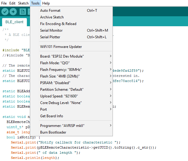
If you have successfully installed the ESP32 core to your Arduino IDE, you should see the following under Tools with the ESP32 Dev Module selected:
Installing the ESP32 Arduino Core
For the more advanced or adventurous route, you can skip the Arduino IDE Boards Manager and install the ESP32 Arduino Core. The pair of Tensilica cores in the ESP32 are Xtensa-based – not your standard ARM or AVR. Fortunately, there is still a GNU compiler available for the ESP32, which opens up a world of possible development environment (IDE) set ups! The rest of this section covers setting up the Arduino IDE with ESP32 support.
In abstracting away a lot of the complicated overhead, the Arduino IDE for the ESP32 also eliminates access to some of the SoC's more advanced features. If you'd like to try your hand at setting up a more advanced toolchain for the ESP32, we recommend checking out Espressif's esp-idf GitHub repository. The esp-idf – short for IoT Development Framework – is Espressif's software development kit (SDK) for the ESP32.
Installing the ESP32 Core
Espressif's official ESP32 Arduino core is hosted here on GitHub. They have a fairly simple set of installation directions to help.
Clone or Download the Core
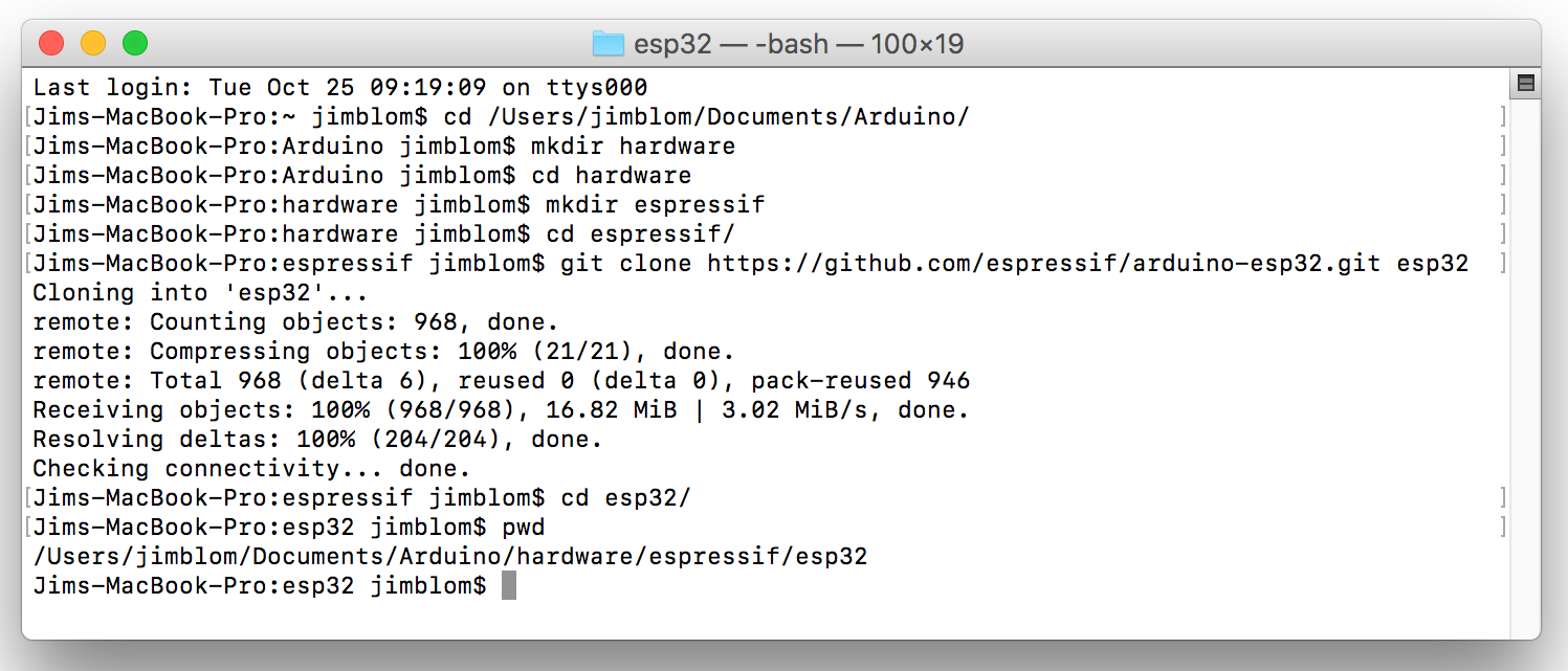
To install the ESP32 board definitions, you'll need download the contents of the esp32-arduino repository, and place them in a "hardware/espressif/esp32" directory in your Arduino sketchbook directory. You can either download those files using the git command line tool, or by downloading them from GitHub.
C:/Program Files (x86)/Arduino/hardware and on Mac that may be /Applications/Arduino.app/Contents/Java/hardware.If you have git, open a terminal, navigate to your Arduino sketchbook, and type:
mkdir hardware
cd hardware
mkdir espressif
cd espressif
git clone https://github.com/espressif/arduino-esp32.git esp32
Those commands will make a "hardware" and "espressif" directories, then download the arduino-esp32 GitHub repository into an "esp32" folder.
If you don't have git, click here to download the core (or click "Download" > "Download ZIP" on the GitHub page), and unzip it to an espressif/esp32 directory in your Arduino sketchbook.
"boards.txt", "platform.txt", and the cores, doc, tools, etc. folders should all live in the esp32 directory.
Install the Xtensa and ESP32 Tools
To compile code for the ESP32, you need the Xtensa GNU compiler collection (GCC) installed on your machine. Windows users can run get.exe, found in the "esp32/tools" folder.
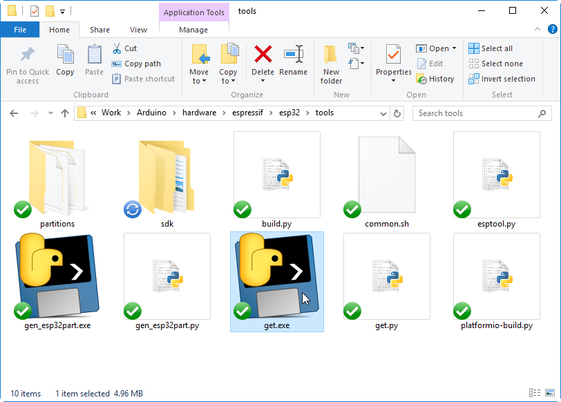
Mac and Linux users should run the tools/get.py python script to download the tools. Using a terminal, navigate to the esp32/tools folder. Then type:
python get.py
The "get.py" python script will download the Xtensa GNU tools and the ESP32 software development kit (SDK), and unzip them to the proper location. You should see a few new folders in the "tools" directory, including "sdk" and "xtensa-esp32-elf" once it's done.
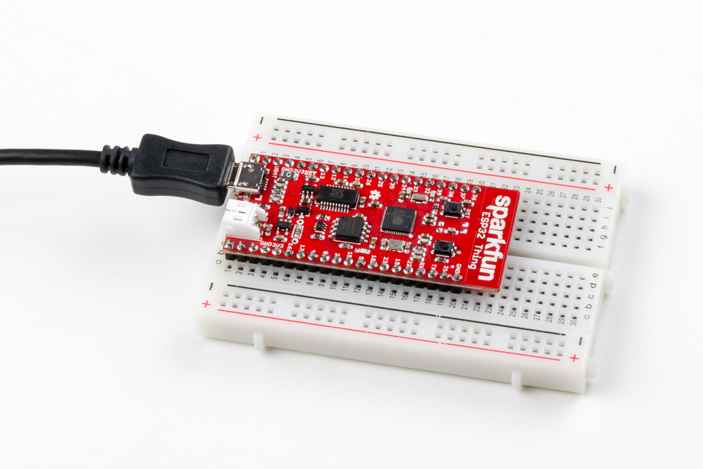
Arduino Example: Blink
With the ESP32 Arduino core installed, you're ready to begin programming. If you haven't already, plug the ESP32 Thing into your computer using a micro-B USB cable.
FTDI Drivers
If you've never connected an FTDI device to your computer before, you may need to install drivers for the USB-to-serial converter. Check out our How to Install FTDI Drivers tutorial for help with the installation.
Once the board is plugged in (and drivers installed), it should be assigned a unique port identifier. On Windows machines, this will be something like "COM#", and on Macs or Linux computers it will come in the form of "/dev/tty.usbserial-XXXXXX."
Select the Board and Port
Once the ESP32 Arduino core is installed, you should see an "ESP32 Dev Module" option under your "Tools" > "Board" menu. Select that.
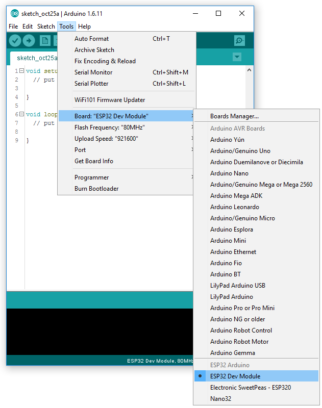
Then select your ESP32 Thing's serial port under the "Tools" > "Port" menu.
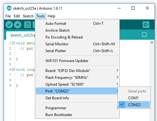
You can also select the "Upload Speed". 921600 baud -- the fastest selectable rate -- will get the code loaded onto your ESP32 the fastest, but may fail to upload once-in-a-while. (It's still way worth it for the speed increase!)
Loading Blink
To make sure your toolchain and board are properly set up, we'll upload the simplest of sketches -- Blink! The LED attached to GPIO 5 is perfect for this test. Plus, with the ESP32 attached to your computer, it's a good time to test out serial. Copy and paste the example sketch below, into a fresh Arduino sketch:
language:c
int ledPin = 5;

void setup()
{
    pinMode(ledPin, OUTPUT);
    Serial.begin(115200);
}

void loop()
{
    Serial.println("Hello, world!");
    digitalWrite(ledPin, HIGH);
    delay(500);
    digitalWrite(ledPin, LOW);
    delay(500);
}
With everything setup correctly, upload the code! Once the code finishes transferring, open the serial monitor and set the baud rate to 115200. You should see "Hello, world"'s begin to fly by.
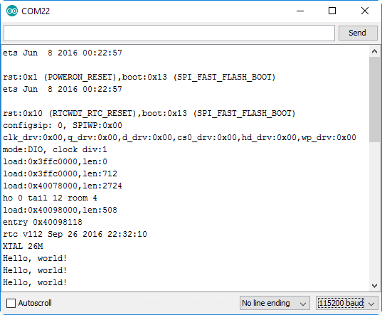
You may also notice that when the ESP32 boots up it prints out a long sequence of debug messages. These are emitted every time the chip resets -- always at 115200 baud.
Arduino Example: WiFi
The ESP32 Arduino core includes a handful of WiFi examples, which demonstrate everything from scanning for nearby networks to sending data to a client server. You can find the examples under the File > Examples > WiFi menu.
Here's another example using the WiFi library, which demonstrates how to connect to a nearby WiFi network and poll a remote domain (http://example.com/) as a client:
language:c
#include <WiFi.h>

// WiFi network name and password:
const char * networkName = "YOUR_NETWORK_HERE";
const char * networkPswd = "YOUR_PASSWORD_HERE";

// Internet domain to request from:
const char * hostDomain = "example.com";
const int hostPort = 80;

const int BUTTON_PIN = 0;
const int LED_PIN = 5;

void setup()
{
  // Initilize hardware:
  Serial.begin(115200);
  pinMode(BUTTON_PIN, INPUT_PULLUP);
  pinMode(LED_PIN, OUTPUT);

  // Connect to the WiFi network (see function below loop)
  connectToWiFi(networkName, networkPswd);

  digitalWrite(LED_PIN, LOW); // LED off
  Serial.print("Press button 0 to connect to ");
  Serial.println(hostDomain);
}

void loop()
{
  if (digitalRead(BUTTON_PIN) == LOW)
  { // Check if button has been pressed
    while (digitalRead(BUTTON_PIN) == LOW)
      ; // Wait for button to be released

    digitalWrite(LED_PIN, HIGH); // Turn on LED
    requestURL(hostDomain, hostPort); // Connect to server
    digitalWrite(LED_PIN, LOW); // Turn off LED
  }
}

void connectToWiFi(const char * ssid, const char * pwd)
{
  int ledState = 0;

  printLine();
  Serial.println("Connecting to WiFi network: " + String(ssid));

  WiFi.begin(ssid, pwd);

  while (WiFi.status() != WL_CONNECTED)
  {
    // Blink LED while we're connecting:
    digitalWrite(LED_PIN, ledState);
    ledState = (ledState + 1) % 2; // Flip ledState
    delay(500);
    Serial.print(".");
  }

  Serial.println();
  Serial.println("WiFi connected!");
  Serial.print("IP address: ");
  Serial.println(WiFi.localIP());
}

void requestURL(const char * host, uint8_t port)
{
  printLine();
  Serial.println("Connecting to domain: " + String(host));

  // Use WiFiClient class to create TCP connections
  WiFiClient client;
  if (!client.connect(host, port))
  {
    Serial.println("connection failed");
    return;
  }
  Serial.println("Connected!");
  printLine();

  // This will send the request to the server
  client.print((String)"GET / HTTP/1.1\r\n" +
               "Host: " + String(host) + "\r\n" +
               "Connection: close\r\n\r\n");
  unsigned long timeout = millis();
  while (client.available() == 0)
  {
    if (millis() - timeout > 5000)
    {
      Serial.println(">>> Client Timeout !");
      client.stop();
      return;
    }
  }

  // Read all the lines of the reply from server and print them to Serial
  while (client.available())
  {
    String line = client.readStringUntil('\r');
    Serial.print(line);
  }

  Serial.println();
  Serial.println("closing connection");
  client.stop();
}

void printLine()
{
  Serial.println();
  for (int i=0; i<30; i++)
    Serial.print("-");
  Serial.println();
}
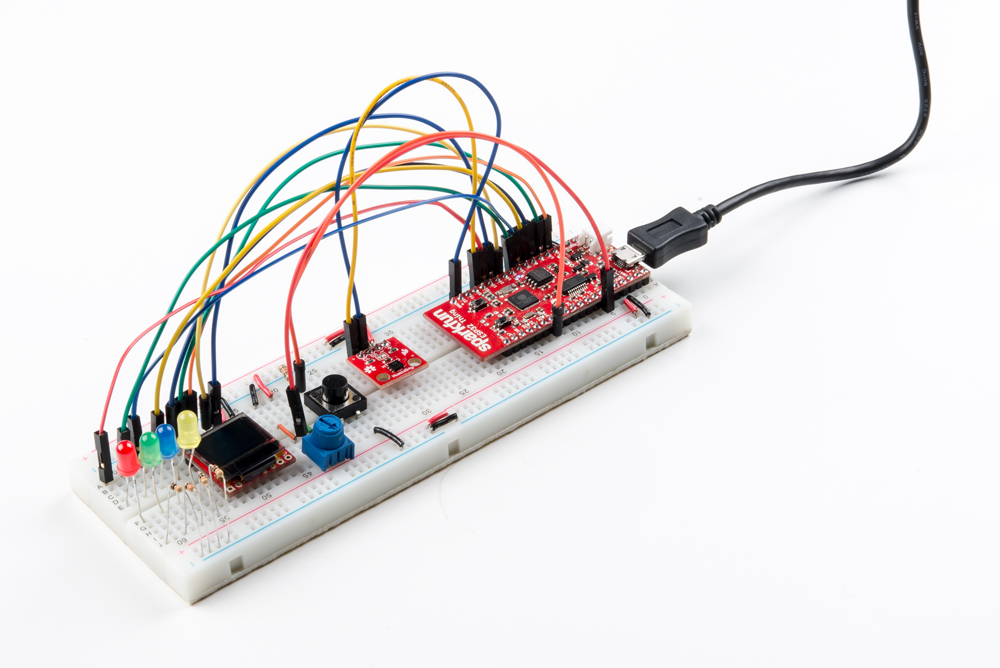
Make sure you fill in the networkName and networkPswd variables with the name (SSID) and password of your WiFi network! Once you've done that and uploaded the code, open your serial monitor.
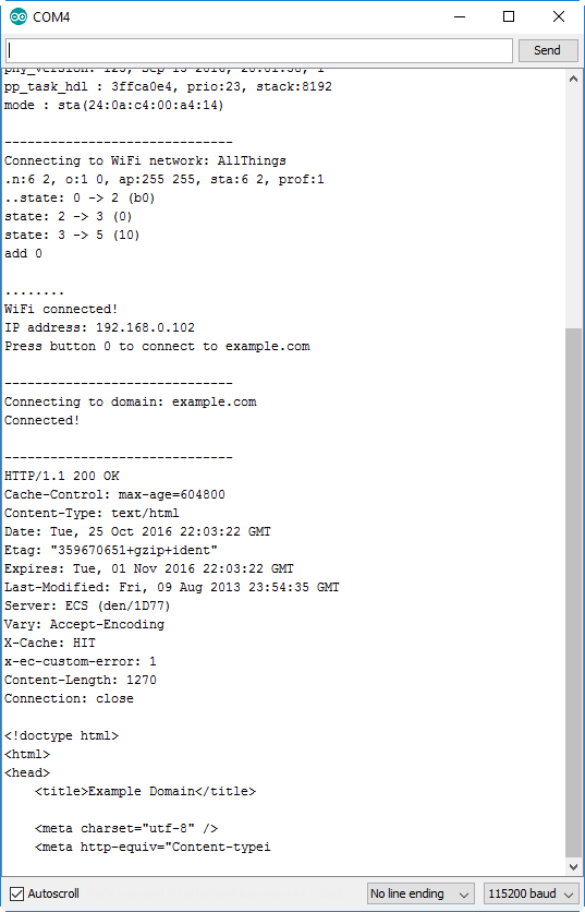
After your ESP32 connects to the WiFi network, it will wait for you to press the "0" button. Tapping that will cause the ESP32 to make an HTTP request to example.com. You should see a string of HTTP headers and HTML similar to the screenshot above.
Using the Arduino Addon
Before we leave you, here are a few tips, tricks, and gotcha's to look out for while you're using the ESP32 Arduino core.
Pin Mapping
The pin number you use for digitalWrite([pin], [value]) or digitalRead([pin]) should match those printed onto the board. You can also reference the graphical datasheet, if the tiny numbers are a strain on the eyes.
Both I2C interfaces are supported by the Wire library. The SDA and SCL pins are assigned, by default, to pins 21 and 22.
| I2C Signal | ESP32 Pin |
|---|---|
| SDA | 21 |
| SCL | 22 |
And the SPI library should support all three possible SPI interfaces. By default, here are the pin mappings for those interfaces:
| SPI Signal | ESP32 Pin |
|---|---|
| MOSI | 23 |
| MISO | 19 |
| SCLK | 18 |
| SS | 5 |
In addition to SPI and I2C, the Arduino core also supports interrupts on any pin with the attachInterrupt() function.
Not Yet Implemented
The Arduino board definitions for the ESP32 are still a work in progress. There are a handful of peripherals and features that have yet to be implemented, including:
- Analog Input (
analogRead([pin])) - Analog Ouptut (
analogWrite([pin], [value])) - WiFi Server and WiFI UDP
- Real-Time Clock
- Touch-controller interface
These peripherals are available (if, also, still in their infancy) in the IoT Development Framework for the ESP32. If your application requires analog input, RTC, or any of the features above, consider giving the ESP-IDF a try!
Resources and Going Further
The ESP32 Thing's design is open-source! You can download, view, and modify the Eagle files (PCB design), checkout the schematic, or suggest revisions on the ESP32 Thing GitHub repository.
- Schematic (PDF)
- Eagle Files (ZIP)
- Board Dimensions (PNG)
- Graphical Datasheet (PDF)
- Datasheet (PDF) (ESP32-D0WDQ6-V3)
- GitHub Hardware Repo
The ESP32 is still in its infancy, but resources are popping up all over the place for the chip. Check out some of these links for more information, documentation, and examples.
- ESP32.com -- Great forums, where you can discuss ESP32 news, get help, or show off your project.
- Espressif ESP32 Resource Page -- A great source for the latest datasheets, reference manuals, and software tools.
- Espressif GitHub Repositories -- Espressif is efforting to be as open-source as possible. Among other things, you'll find repositories for Arduino ESP32 support, SDK's, and even a proof-of-concept NES emulator hosted on their GitHub page.
You can also check out these links to go further.
- ESP-IDF -- IoT Development Framework -- If you want to take your development environment up a step from Arduino, this should be your first step into ESP32 software development. Some notes on the IDF:
- The IDF is well-documented. Check out the set up guides (for Windows, Mac or Linux) for help getting your environment set up. For help with the API's and data structures, check out esp32.info.
- There are a handful of example applications.
- Use the ESP-IDF project template, once you're ready to start creating applications of your own.
- Blynk -- Blynk allows you to control IoT development boards with an easily configurable iOS/Android app. And it already supports the ESP32!
- Download the Blynk Arduino Library and load the ESP32 example onto your ESP32 Thing. Then download the app and start blinking!
Looking for additional functionality with the ESP32? Check out the ESP32 Thing Plus with the ESP32 WROOOM module.
ESP32 Thing Plus Hookup Guide
March 7, 2019
For more related tutorials, check out the following tutorials tagged with ESP32.
Introduction to MQTT
LuMini 8x8 Matrix Hookup Guide
ESP32 Relay Web Server
MicroMod GNSS Carrier Board (ZED-F9P) Hookup Guide
If you need some project inspiration, check out some of these IoT-focused projects and get making!
LED Cloud-Connected Cloud
Photon Remote Temperature Sensor
ESP8266 Powered Propane Poofer
IoT Industrial Scale
Or check out these related blog posts.