ESP32 Relay Web Server
 Elias The Sparkiest
 Introduction
The goal of this project is to have a website hosted on an ESP32 that controls any relay controlled device connected to a local network and keeps a dynamically updated state of those devices. The website must look good but more importantly, be responsive. The goal of this tutorial is to be instructive in the topics associated with each component that make up the project. Clearly it will outline the steps to get the project up and running, but it will also delve into each concept with some depth to give you more information on how this project works; with some attempt to keep you, the reader, from falling asleep. Through out this tutorial "device" is synonymous with "relay" because a relay will be controlling the device.
This is a continuation of the Infrared tripwires to automate light switching and The ESP32 Web Server blog posts. After achieving the primary goal outlined above, there will be another section added to go over how to integrate the IR tripwires as a "user" controlling the relays. Let's go over what each individual piece of the project looks like.
How - ESP32 and SPIFFS
Using an ESP32 or ESP8266 and utilizing the SPIFFS Filesystem (SPI Flash File System) library, the ESP module suddenly has a file system! This opens up many possibilities because we can now store and open webpage files, small images, and files for tracking states of the devices. This tutorial uses an ESP32 in place of an ESP8266 because of it's larger memory capacity. More memory increases our file size capabilities and gives the micro-controller longer life because we're not butting up against its maximum storage capacity.
Responsiveness - ESPAsync and Websockets
The ESPAsync Library includes example code which provides the basis for the tutorial's source code. The ESPAsync library, as the name suggests, manages asynchronous web requests. This is important; the website needs to handle a case in which two people are on the webpage at the same time, or when someone trips the IR tripwire while someone is on the webpage. Because the website is asynchronous by design that means it will queue requests in the background without explicit code in the Arduino sketch and can change the state of the relay and the website's indicators as requested.
"State Machine" - ArduinoJson and JSON files
The state of each device will be kept in a JSON file within the SPIFFS file system. The JSON file will be very simple:
{
    "relay_states": [0,0,0,0]
    "host_name":"SSID":,
    "password" : "password"

}
Alternatively a simple text file could do the same thing. So why a JSON file? JSON being a markup language is designed to organize data into parsable objects which makes the interaction with JSON files more intuitive. In addition WiFi network names and passwords can also be saved within other files without having to modify the Arduino Sketch. To parse the JSON file we'll leverage the very well written and very well documented ArduinoJson Library.
The Feel - BootStrap, CSS and Javascript
The web page's theme and its' scalability from desktop to mobile phone will be made possible with Bootstrap - a toolkit for HTML, JS, and CSS. The tutorial will outline how to keep the file size small and get the most out of the simplicity of the Bootstrap toolkit.
What's next?
You can check back here to see what's next to be updated, this will be updated as the tutorial grows. If you have any questions or suggestions, place them in the comments below.
To Do
1. Add section on Bootstrap fies: bootstrap.min.CSS and bootstrap.min.JS. What are they and what do they do?
2. Add section on the ESP32 File Structure and where files live.
3. Add section on JSON files and Arduino JSON to store data related to WiFi settings and the state of each individual relay.
4. Add section on AJAX requests and Websockets in place of straight GET requests.
5. Add relay control function to our requests.
6. Add Hardware Section for ESP32 and Relay.
7. Add trouble-shooting section to tutorial.
8. Update tutorial with the Infrared tripwires Arduino Sketch and fill in details on the hardware hookup.
Arduino Software
Library Installation
There's a number of libraries and tools to download and install for this project. If you haven't installed a library before, then check out this helpful tutorial here. All but the ArduinoJSON library must be installed manually, that is, dropping the folder into your Arduino's libraries folder under documents assuming you're using Windows. All of the links are also at the the project's Github repo here and linked in the source code (home.ino) Arduino sketch. I've also included a links to all information covered in this tutorial, including the libraries below, in Resources and Going Further.
- Async TCP Library for ESP32 (Github Link) - Dependency for ESPAsync below
- ESPAsync Web Server for ESP8266 and ESP32 (Github Link) - Asyncronous Web Request Library
- SPIFFS (Github Link) - Allows the user to use ESP32's Memory for file storage.
- ESP32 File Uploader Tool (Github Link) - Tool for uploading files onto and ESP32
- Arduino JSON Library (Website) - For serializing and de-serializing information.
Take special care when installing the fourth item ESP32 File Uploader Tool. This tool is not a library installed in the normal location because it's a tool specific to ESP32's hardware. For this reason it's installed within the Tools directory of the ESP32 Hardware files. Follows the instructions outlined in the link above carefully.
Source Files
Download the Source Files
After installing the Libraries detailed above you can now download the source files here or clink the button below. From here you can modify the wifi credentials within the home.json file and then move onto the Hardware section. However, let's look at the overall file structure within the zip file.
What's inside the Source Files?
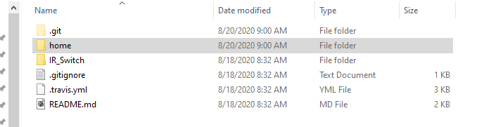
At the top you can see the Home directory. This directory has the scripts, images, and style sheets that control the main web page. Below that is the IR_Switch Directory which has the sketch that controls the IR tripwires. Let's look inside the home directory.
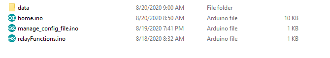
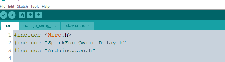
Here home.ino is supported by two other .ino scripts. If you open home.ino in Arduino you'll see a few tabs that include the other two Arduino sketches: manage_config_file.ino and relayFunctions.ino. The sketch was split into separate files for better organization because home.ino was simply too long to easily navigate. When you upload these onto the ESP32 all three of the sketches will be uploaded as one single sketch. The data folder here holds the files that will be uploaded to the ESP32 module using the ESP32 upload tool. This is different then uploading a sketch.
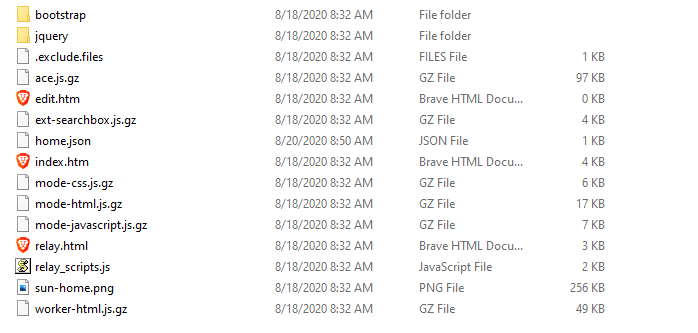
The name of the folder is specifically named data because the ESP32 upload tool looks for a "data" folder in the home directory of the currently opened sketch: home.ino. The contents of data are placed onto the ESP32 as a file system allowing us to access them for our webpage. Many of the pages here are simply the supporting cast members of the webpage - more on that in the Explanation of the Webpage Files below, with the exception of home.json which has the wifi credentials and the states of the relay.
Installing Source Files
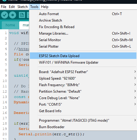
This is quite simple, as long as everything is in the right place. Working from within the Arduino IDE with the home.ino sketch open you'll first want to upload the files, not the sketch, onto the ESP32 using the ESP32 file upload tool. Assuming that you've put it into the correct place outlined on the Upload tools Github repo, under Tools you'll see the ESP32 Sketch Data Upload.
This will take the data folder and put everything within it onto the ESP32. Don't forget to modify the wifi credentials before uploading the files to save yourself from uploading the files a second time. Next you'll upload the sketch as usual, remember that while there are three files located within this folder, they will all get uploaded as one single sketch.
Explanation of Webpage Files
A Brief note on CSS, JS, and HTML Files
HTML literally makes up the backbone of any website. It's a markup language (like JSON), meaning that it's purpose is to provide information on the many sections of the website! For example:
<h1>Press Me!</h1>
The "attribute" of the text "Press Me!" is h1, which is a header of a certain size. Other headers include h2, h3, etc, all of which just differ in size. To give a website its' look and feel using just HTML, additional attributes have to be added to the text to define color, size, or font.
<h1><font color="red"> Press Me! </font></h1>
Notice the "font color" attribute in addition to the header attribute. Now imagine defining other things like size, or a different font and then imagine that your website is finished, but you've decided all of these headers should be green. What an increasingly painful thing to have to manage. Enter Cascading Style Sheets. CSS files live apart from the HTML files and can determine what every header file should look like in a single line of code. No need to assign attributes to every header in the HTML file itself! Simply import it at the top of your HTML file!
Easy, now let's breifly discuss Javascript. Javacript is the programming language that determines what happens when a button on the website is pressed. In this project, Javascript will change the text on the button when a button is pressed and then send requests to the ESP32 to flip on a relay. Again, import this JS file at the top of your HTML file.
Enter the Bootstrap
Bootstrap is a toolkit that provides pre-written CSS and JS files with a focus on making websites scalable to fit large and small screens. All of the webpage files are already included in the source files but if you want to check the source and learn a bit more then the following link will send you to the Bootstrap download webpage. None the less let's discuss which files were kept from the download below and why.
After downloading the Bootstrap source files and unzipping them, there are two folders, one labeled CSS (Cascading Style Sheets) and another labeled JS (Javascript). Ignore any file with the following modifier in their names:
- grid
- reboot
- map
- bundle
.....and locate the files labeled bootstrap.min.js and bootstrap.min.css. These files are the "minified" versions of the CSS or JS files found in the same folder, but have had all of the white spaces removed to decrease the file size. Just how much?
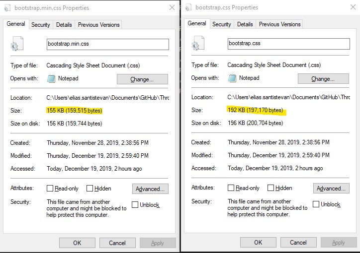
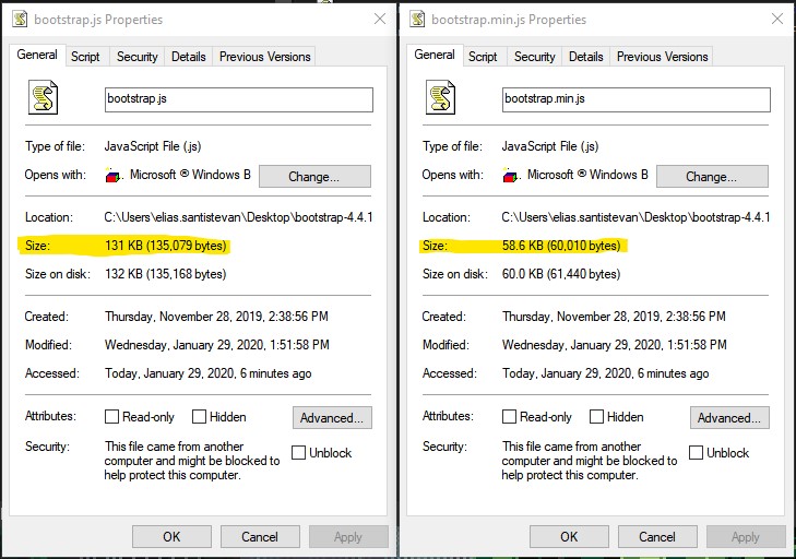
A saving of over 40KB - 70KB per file will make a huge difference in the size impact on the ESP32. The rest of these files can be ignored for this project. The following button links to a website that offers Bootstrap CSS files with different thematic colors. For example, in the image below is the "Solar" theme (based on the popular Text Editor coloring scheme) - about half way down the webpage. Simply click download and get the bootstrap.min.css file which can/will replace the CSS source file downloaded from Bootstrap's web page.
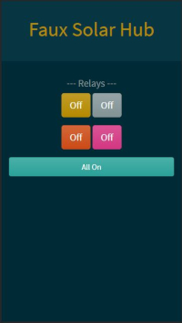
To help give context to this project, here is the HTML for the website pictured above, which includes imports of the Bootstrap JS and CSS files at the top, lines for button creations, and the title bar at the top.
<!DOCTYPE html>
<html lang="en">
    <head>

        <!-- Required meta tags -->
        <meta charset="utf-8">
        <meta name="viewport" content="width=device-width, initial-scale=1, shrink-to-fit=no">

        <!-- Bootstrap CSS -->
        <link rel="stylesheet" href="bootstrap/bootstrap.min.css" media="screen">

        <script src="jquery/jquery.min.js"></script>
        <script src="bootstrap/bootstrap.min.js"></script>
        <script src="relay_scripts.js"></script>

    </head>

  <body>

    <div class="jumbotron jumbotron-fluid" style="text-align:center">
      <h1 class="text-primary">Faux Solar Hub</h1>
    </div>

    <!-- Buttons ================================================== -->
    <div class="container" style="text-align:center">
        <h5>---  Relays  ---</h5>
        <div class="btn-group-lg " role="group" aria-label="Relay Buttons">
            <button type="button btn-lg" class="btn btn-primary btn-lg" id="relay1" data-toggle="buttons">Off</button>
            <button type="button btn-lg" class="btn btn-secondary btn-lg" data-toggle="buttons" id="relay2">Off</button>
        </div>
        <p>
        <div class="btn-group-lg" role="group" aria-label="Relay Buttons">
            <button type="button btn-lg" class="btn btn-warning btn-lg" data-toggle="buttons" id="relay3">Off</button>
            <button type="button btn-lg" class="btn btn-danger btn-lg" data-toggle="buttons"  id="relay4">Off</button>
        </div>
    </div>

    <div class="container" style="text-align:center">
      <p>
        <p>
        <button type="button btn-lg" class="btn btn-success btn-block" data-toggle="buttons" id="totalControl">All On</button>
        </p>
      </p>
    </div>

  </body>
</html>
Sate Machine - De/serializing Data
As mentioned above we'll be using ArduinoJSON to store not only the state of the relays "On" or "Off", but also Wifi credentials.
Deserialization
The tutorial on the Arduino JSON website is pretty darn fantastic and so this won't be a regurgitation of the information they have there, but I will go over the relevant components to this project.
In brief, deserialization is how we'll read the JSON document on the ESP32 (home.json) to get the necessary information for loading our wifi settings. Let's again take a look at the JSON file we have within the data folder that is uploaded to the ESP32 using the ESP32 file upload tool.
{
  "SSID" : "Wifi name",
  "Password": "password",
  "relay_states" : [0,0,0,0]
}
Ignoring the "relay states" for now, we see that it's a rather simple document. To get this information, we're doing two main things within the manage_config_file.ino sketch. The first is opening the the JSON file to get to the wifi credentials and checking for errors.
 File configFile = SPIFFS.open(configPath, "r");
  if(!configFile)
    Serial.println("Could not open file.");
This is simple enough, we need the absolute path to the file: configPath, which is /home.json. This is defined in the main home.ino sketch. The next main thing is to take the wifi credentials within the JSON file and save them so that they can be used to connect to the WiFi. This process is not as straight forward as it may seem but it's well worth the effort.
  const size_t capacity = JSON_ARRAY_SIZE(4) + JSON_OBJECT_SIZE(3) + 100;
  DynamicJsonDocument doc(capacity);

  DeserializationError err = deserializeJson(doc, configFile);

  if(err) {
    Serial.print("Deserialization error:");
    Serial.println(err.c_str());
  }

  doc["SSID"].as<String>().toCharArray(ssid, 30);
  doc["Password"].as<String>().toCharArray(password, 30);

  configFile.close();

}
First and foremost you have to determine the size of the information that you're deserializing. On the ArduinoJSON website they include how to calculate the size manually but even better they provide a tool that calculates the size automatically. Take note that you want the size needed for deserializing and not serializing. I believe the size already in place should be sufficient for 90 percent of people's WiFi network names and passwords, but in case you get a "NoMemory" error, this is the place to modify.
Next a "doc" object is created with the given size (this will hold our information from the JSON file), and is passed to deserializeJson along with the configFile. If there is an error, it will be printed out to the Serial terminal, but if not we'll take that information and save it to ssid and password. Now this looks a bit funky. Let's break the two deserialization lines down for clarification.
  doc["SSID"].as<String>().toCharArray(ssid, 30);
  doc["Password"].as<String>().toCharArray(password, 30);
I could (and I tried) to do this:
const char* ssid = doc["SSID"];
This is correct because doc returns a const char pointer. However since we're reading from a file, that will later be closed, this pointer will not point to anything. So we don't want to save a pointer to our information, we would rather save the information itself. So we use some built in C++ magic to take the wifi credentials being pointed at and save them as an array of characters. If that's over your head, don't worry, just leave it as is and everything works.
Serializing
Coming SOON!
Hardware Assembly - ESP32 Web Server and Quad relay
Hardware for the web server:
The parts I'm using for this part of the project are the following (not listed is the lamp).


Qwiic Cable - 200mm
PRT-14428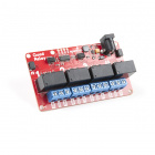
SparkFun Qwiic Quad Relay
COM-16566Hardware Hookup
Here we get to cheat a bit because we're using Qwiic capable boards. Power needs to be provided to the ESP32, to the relays on the Qwiic Quad Relay, to the IC on the Qwiic Quad Relay, and an I2C connection needs to be made as well. Wall warts are providing power to both the relays on the Qwiic Quad Relay and to the ESP32 in the image below. Then, to provide power and establish a connection over I2C between the Qwiic Quad Relay and the ESP32, a Qwiic cable is used. No soldering necessary, very very nice.
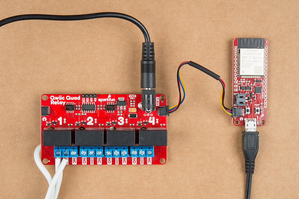
Not listed is the connection from the relay to the lamp. First, a short review on relays.
How does a relay work?
Simply put, relays are switches. However, they are switches utilizing the magnetic property of electricity to allow the switch to be separate from what flips it. This is the root of what makes them so special - utilizing a low voltage system (3.3V in this case) a person can control the electricity coming out of the wall and to a device like a lamp! Relays are differentiated by how much voltage is needed to flip the switch, and how much power can travel across the switch when it's flipped (some combination of voltage and current). The relays on the Qwiic Quad relay can handle five amps at 250V AC and requires at least 3.3V to flip the switch.
Lamp hookup
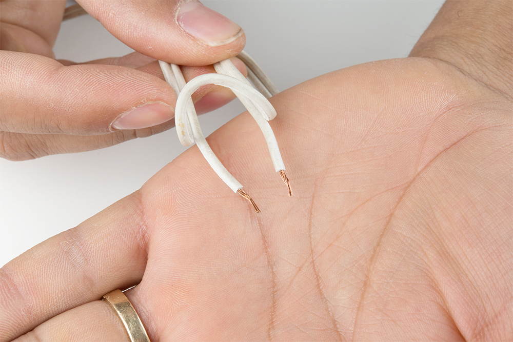
To hookup the lamp to the Qwiic Quad Relay, one of the connections from the lamp will have to be broken so that it can later be closed by the relay when we turn it on. To do that, cut one side of the cable and then strip the cable to expose the protected wire underneath.

Now peel the wire apart and strip the two ends.
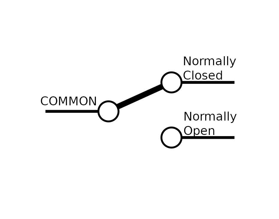
Put one of the ends in the Common (COM) input of the screw terminal and the other end in the Normally Open (NO) input. The common input is the center of our switch, and the normally open input is the end of the switch that will be closed when the switch is flipped. The image below should help clear any confusion.
That's it!
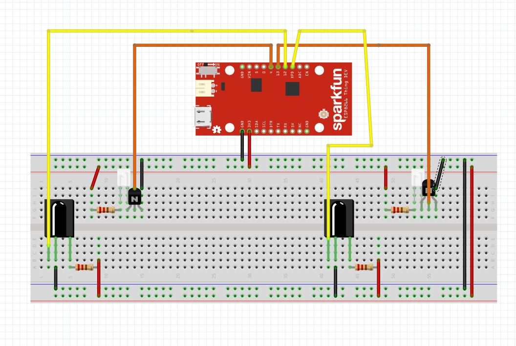
Hardware Assembly - Infrared Trip Wire
Hardware for the Infrared Tripwires:

Resources and Going Further
- ESPAsync Library - Web Server Library
- AsycTCP - Dependent library for ESPAsync Library
- SPIFFS - SPI Flash File System
- ESP32 File Upload tool - Tool to upload web page files onto ESP32
- Node.js - Package manager for HTML files
- Bootstrap page - Toolkit for making web pages dynamic and slick.