Audio Codec Breakout - WM8960 Hookup Guide
 QCPete,
  bboyho
Hardware Hookup
There are a number of ways to connect to the input and output pins of the WM8960. We will go over each .
Soldering
Header pins were left off the Audio Codec Breakout to allow users the flexibility of connecting any type of 0.1"-spaced header to the board. Depending on your connections, you may need to solder additional breakout boards and adapters. For temporary connections to the I/O pins, you could use IC hooks to test out the pins. However, you'll need to solder headers or wires of your choice to the board for a secure connection. For the scope of this tutorial, we will be soldering male header pins on the board and wiring the circuit on a breadboard. Here are a few tutorials to connect to the pads depending on your personal preference.
How to Solder: Through-Hole Soldering
Working with Wire
Power
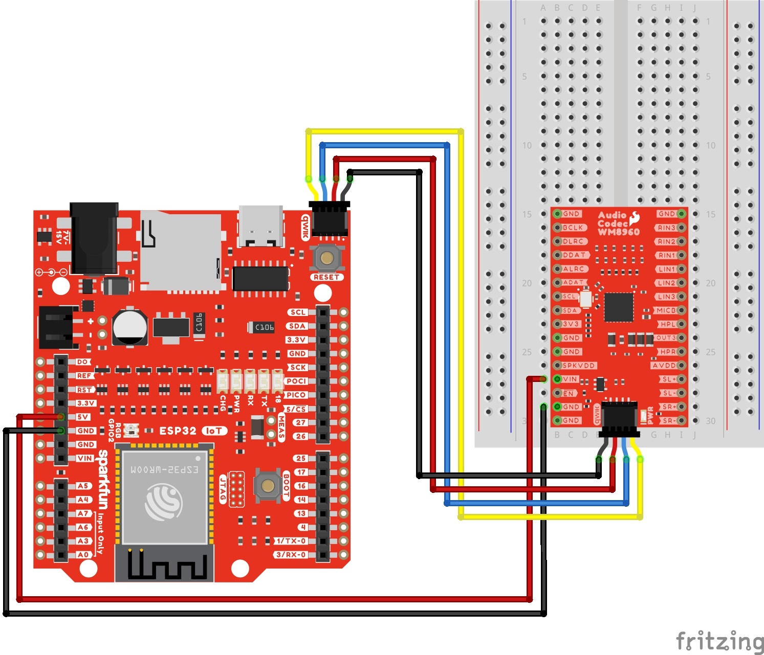
To power the WM8960 appropriately, you will just need to provide power to VIN and the 3V3 pins. As stated in the Hardware Overview: Power, you can take advantage of your development board's voltages without adjusting jumpers. We recommend making the following connection listed in the table.
| Audio Codec - WM8960 | IoT RedBoard - ESP32 |
|---|---|
| VIN | 5V |
| GND | GND (Additional Ground, optional) |
| Qwiic Cable's 3.3V pin (or 3.3V) |
Qwiic Cable's 3.3V pin (or 3.3V) |
| Qwiic Cable's GND pin (or GND) |
Qwiic Cable's GND pin (or GND) |
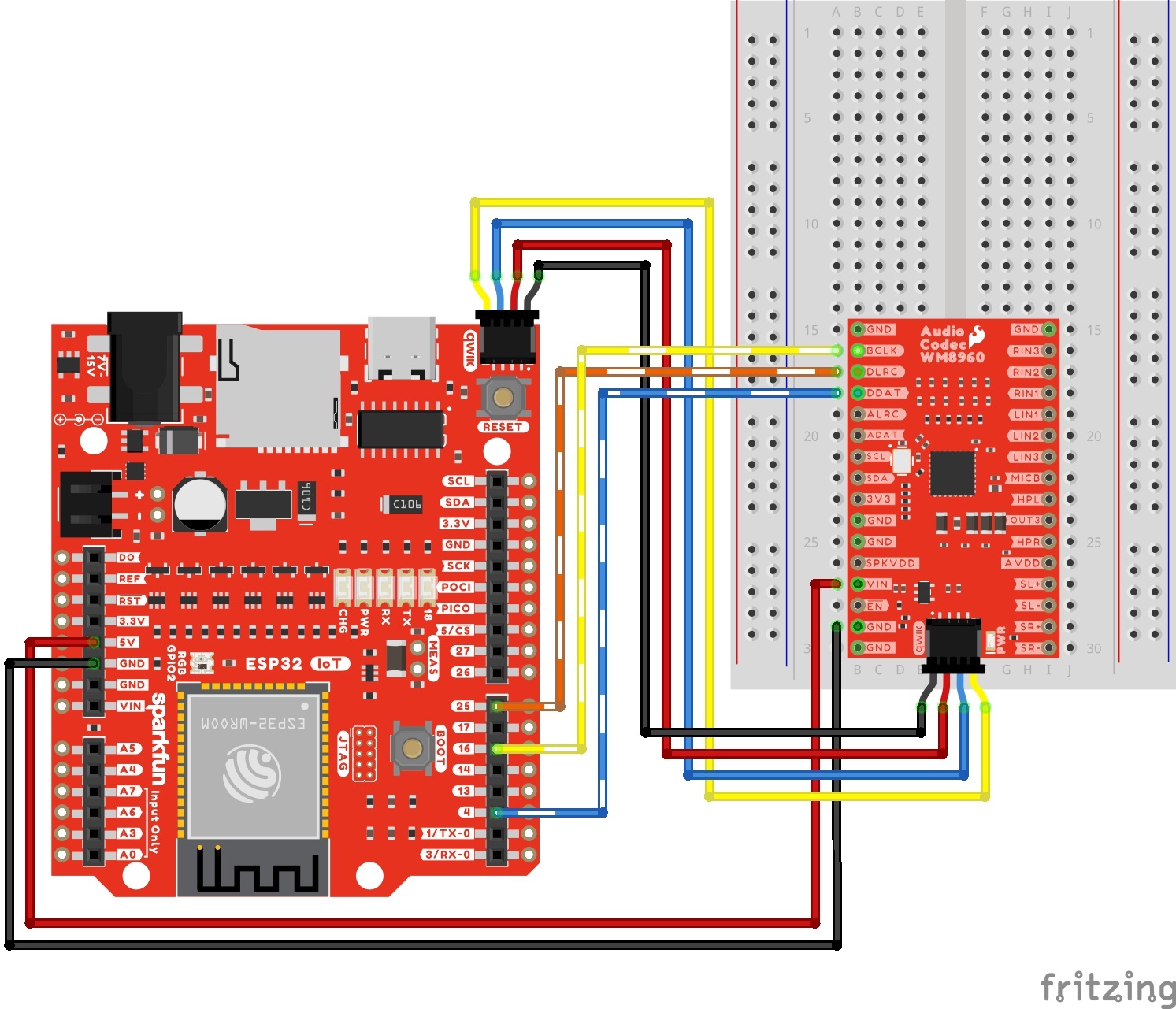
Using wires and the Qwiic cable to power VIN and 3V3, your circuit should look similar to the circuit diagram below. We will use this method to power the audio codec for the proceeding circuit diagrams.

Depending on your setup, you could provide a separate input voltage to the SPKVDD and VDD. Just make sure to adjust the jumpers on the back as necessary.
For users providing their own power supply for SPKVDD and AVDD, make sure to keep the jumpers open.
Qwiic and I2C
To configure the I2S settings or signal path, you will need to connect to the I2C port. Users can save some time wiring this part of the circuit up by adding a Qwiic cable between the audio codec breakout and the IoT RedBoard ESP32. As an alternative, users could also solder to the PTH as well. We recommend making the following connection listed in the table.
| Audio Codec - WM8960 | IoT RedBoard - ESP32 |
|---|---|
| Qwiic Cable's SCL pin (or SCL) |
Qwiic Cable's SCL pin (or SCL) |
| Qwiic Cable's SDA pin (or SDA) |
Qwiic Cable's SDA pin (or SDA) |
| Qwiic Cable's 3.3V pin (or 3.3V) |
Qwiic Cable's 3.3V pin (or 3.3V) |
| Qwiic Cable's GND pin (or GND) |
Qwiic Cable's GND pin (or GND) |
Surprise! Your connection is basically the same as the circuit diagram in the previous section. We just highlighted the circuit connection for I2C data and clock lines here.
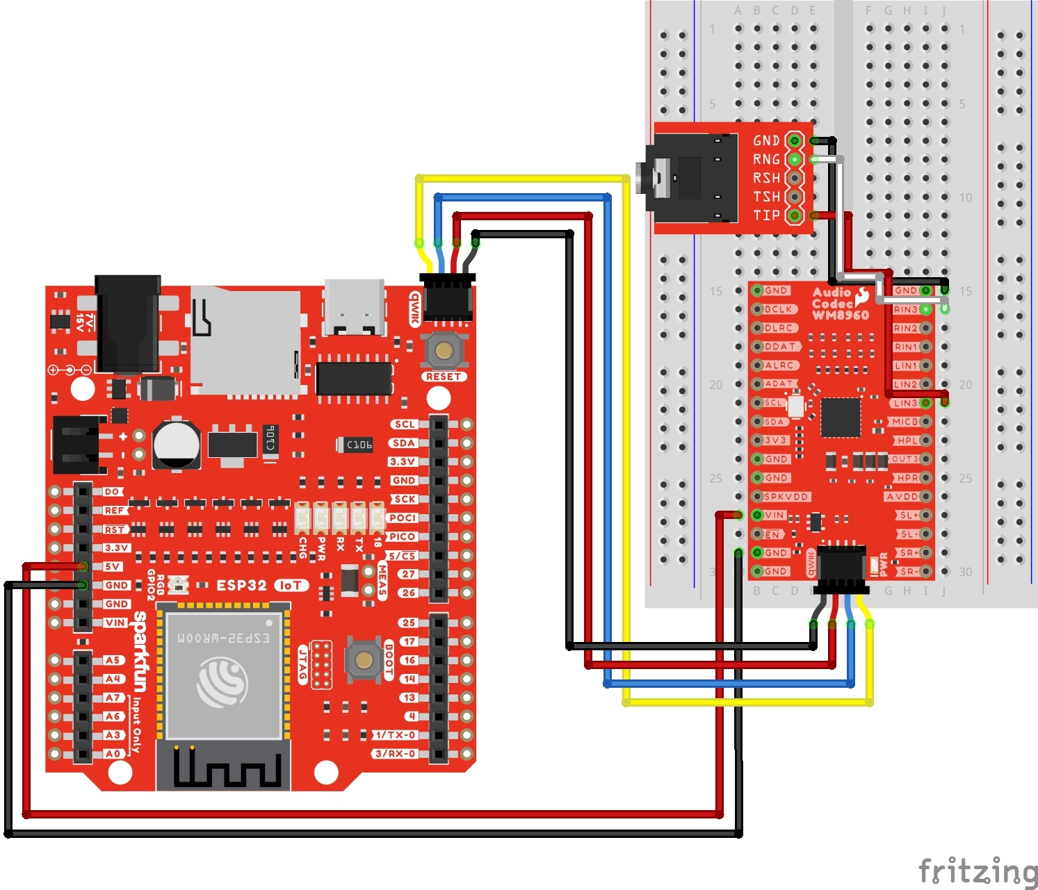
Line Input 3
The following connection is for a line level input 3. For simplicity, the table does not include the power and I2C pins.
| Audio Codec - WM8960 | TRS Connector |
|---|---|
| LINPUT3 | Tip |
| RINPUT3 | Ring |
| GND | Sleeve |
Your circuit should look similar to the circuit diagram below.
Line Input 2
The following connection is for a line level input 2. For simplicity, the table does not include the power and I2C pins.
| Audio Codec - WM8960 | TRS Connector |
|---|---|
| LINPUT2 | Tip |
| RINPUT2 | Ring |
| GND | Sleeve |
Your circuit should look similar to the circuit diagram below.

Line Input 1
The following connection is for a line level input 1. For simplicity, the table does not include the power and I2C pins.
| Audio Codec - WM8960 | TRS Connector |
|---|---|
| LINPUT1 | Tip |
| RINPUT1 | Ring |
| GND | Sleeve |
Your circuit should look similar to the circuit diagram below.

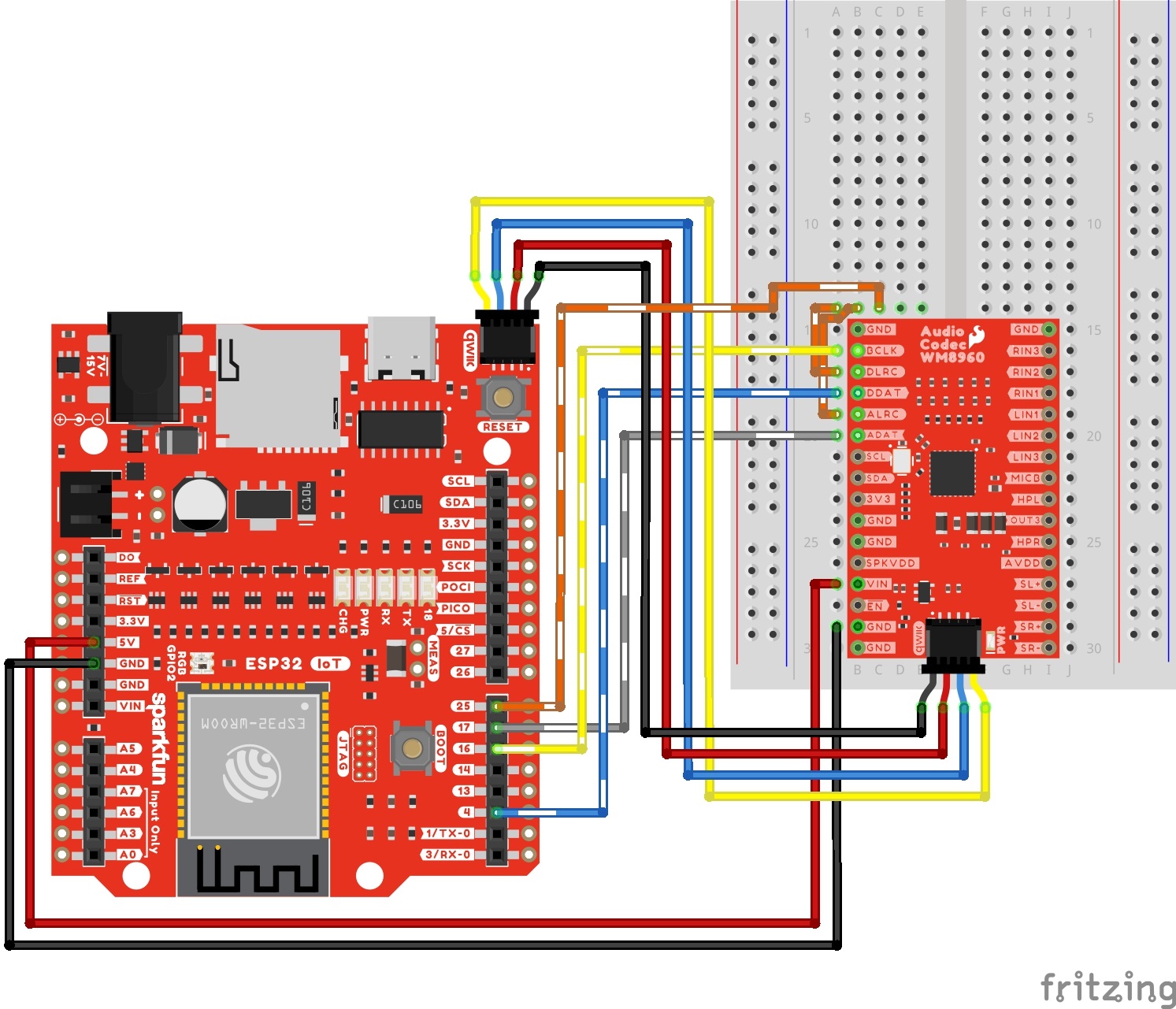
I2S Passthrough
The following connection is for passing an audio source through the ADC and immediately back to the DAC. For simplicity, the table does not include the power and I2C pins. Note that this is for setting the codec as a I2S peripheral.
| Audio Codec - WM8960 | IoT RedBoard - ESP32 |
|---|---|
| DACDAT | 4 |
| BCLK | 16 |
| ADCDAT | 17 |
| DACLRC | 25 |
| ADCLRC | 25 |
Your circuit should look similar to the circuit diagram below.
I2S Decoder
The following connection is for decoding audio. One example is if users connect an audio Bluetooth® device (such as your phone or laptop) to the ESP32 and stream music wirelessly. For simplicity, the table does not include the power and I2C pins. Note that this is for setting the codec as a I2S peripheral.
| Audio Codec - WM8960 | IoT RedBoard - ESP32 |
|---|---|
| DACDAT | 4 |
| BCLK | 16 |
| DACLRC | 25 |
Your circuit should look similar to the circuit diagram below.
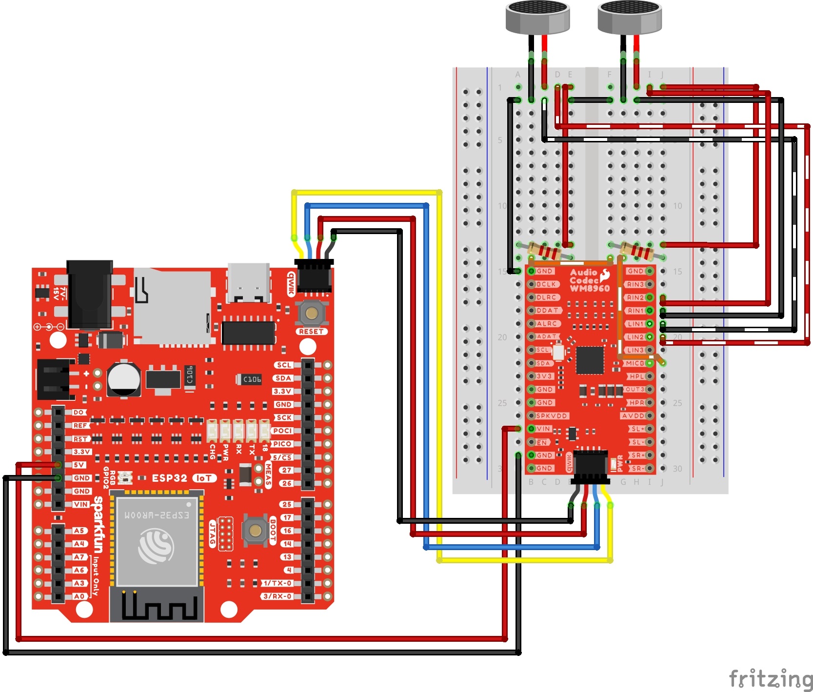
Differential Microphone Input
The following connection is for connecting differential microphones to the audio codec. When using a pseudo-differential microphone configuration, make sure to include a 2.2kΩ resistor between the MICBIAS and the + terminals of each differential microphone. You will also need to set voltage on the MICBIAS pin. For simplicity, the table does not include the power and I2C pins.
| Audio Codec - WM8960 | Resistor | Electret Microphone |
|---|---|---|
| GND | Left Mic - | |
| LINPUT1 | Left Mic - | |
| LINPUT2 | Left Mic + | |
| MICBIAS | 2.2kΩ | Right Mic + |
| GND | Right Mic - | |
| LINPUT1 | Right Mic - | |
| LINPUT2 | Right Mic + | |
| MICBIAS | 2.2kΩ | Right Mic + |
Your circuit should look similar to the circuit diagram below.
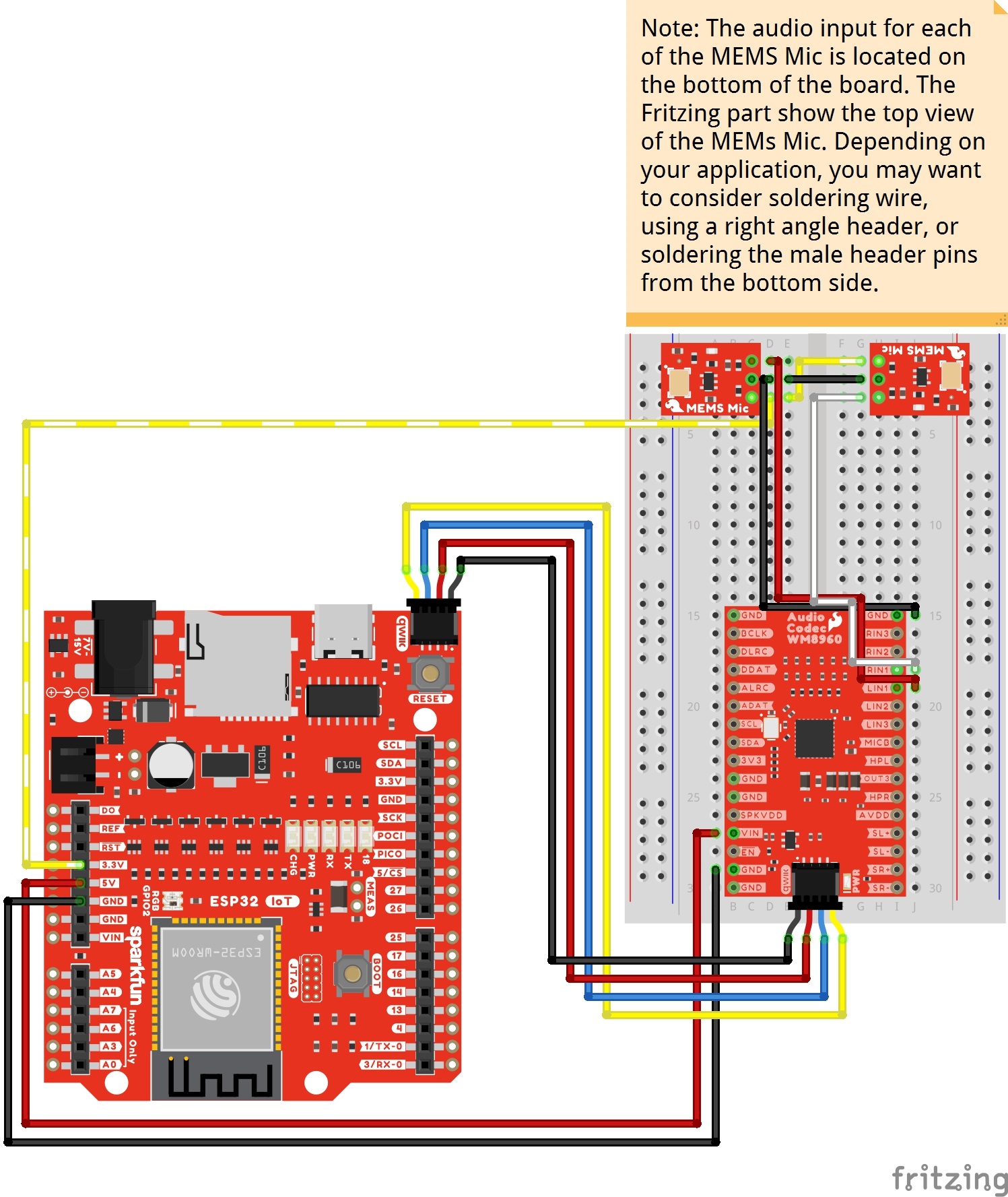
Single Ended Microphone Input
The following connection is for connecting single ended microphones to the audio codec. Instead of using a line level input from the TRS connector, users can also connect unbalanced microphones (these are usually microphones with an amplifier on the breakout boards and have one audio output pin) to the left and right pins of INPUT1. Make sure to also connect power and GND to the boards. For simplicity, the table does not include the power and I2C pins between the ESP32 and WM8960.
| Audio Codec - WM8960 | Single Ended Microphone (Left) | Single Ended Microphone (Right) | IoT RedBoard - ESP32 |
|---|---|---|---|
| Qwiic Cable's GND pin (or GND) |
GND | GND | GND |
| LINPUT1 | AUD | ||
| RINPUT1 | AUD | ||
| Qwiic Cable's 3.3V pin (or 3.3V) |
3.3V | 3.3V | 3.3V |
Your circuit should look similar to the circuit diagram below.
Headphone Output
Based on the recommended output configuration from the datasheet, we will be using a capless headphone output in this tutorial.
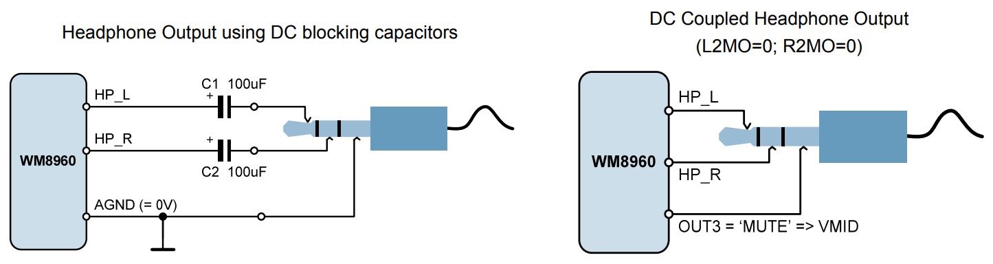
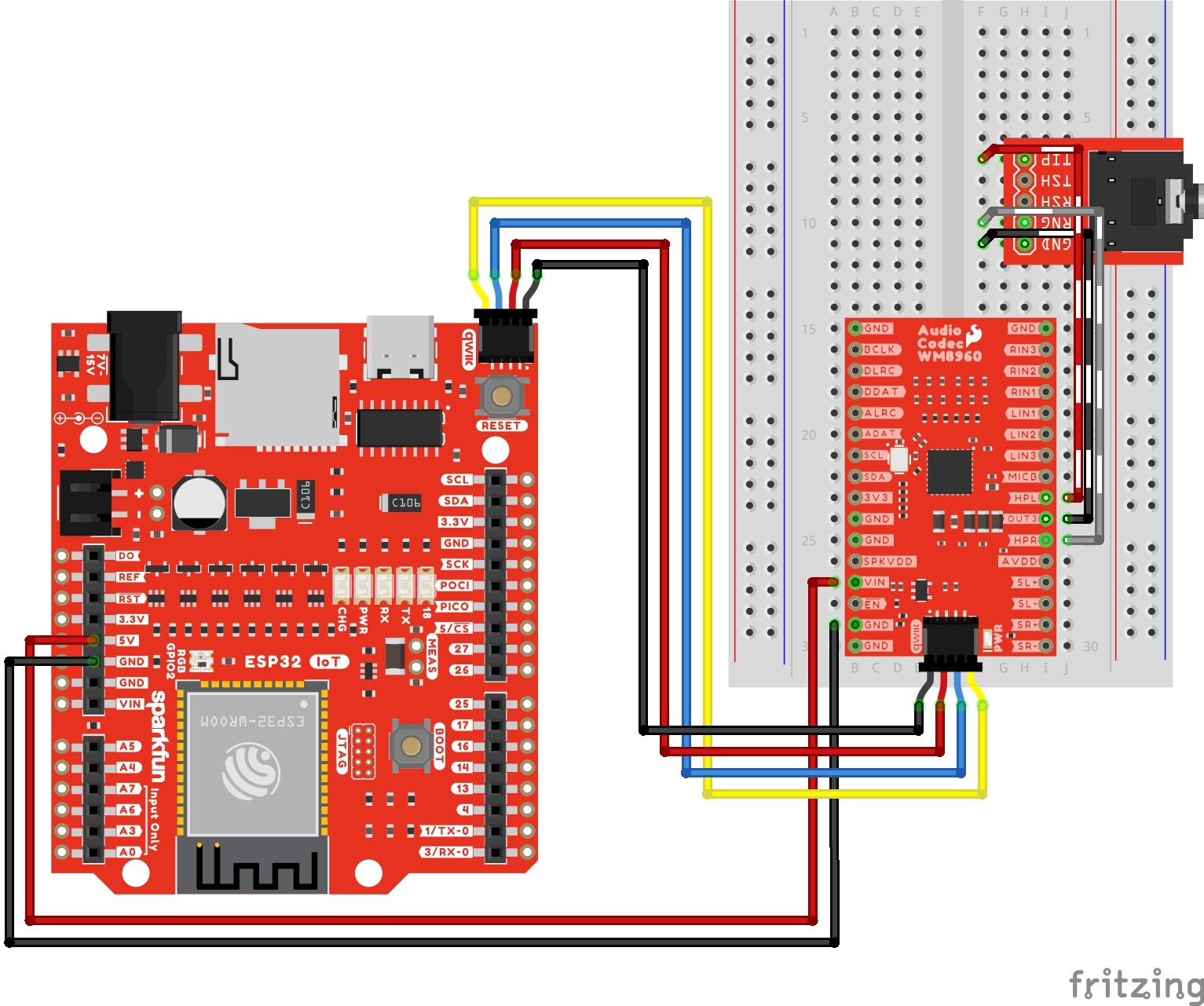
The following connection is for connecting headphones to the audio codec's headphone output. For simplicity, the table does not include the power and I2C pins.
| Audio Codec - WM8960 | TRS Connector |
|---|---|
| HPL | Tip |
| HPR | Ring |
| OUT3 | Sleeve |
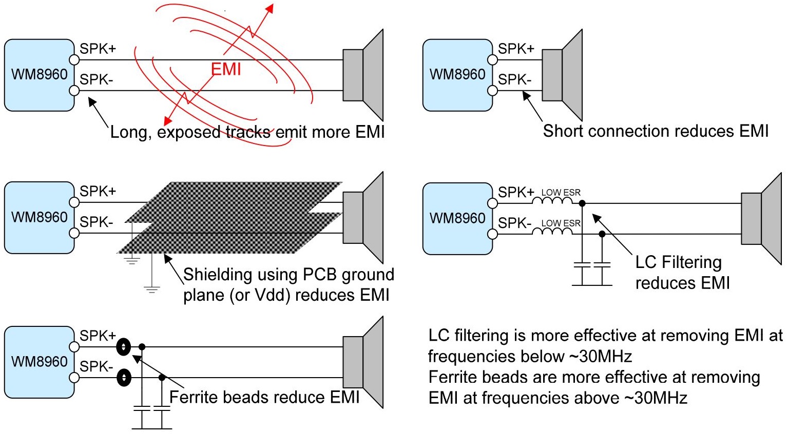
Differential Speaker Output
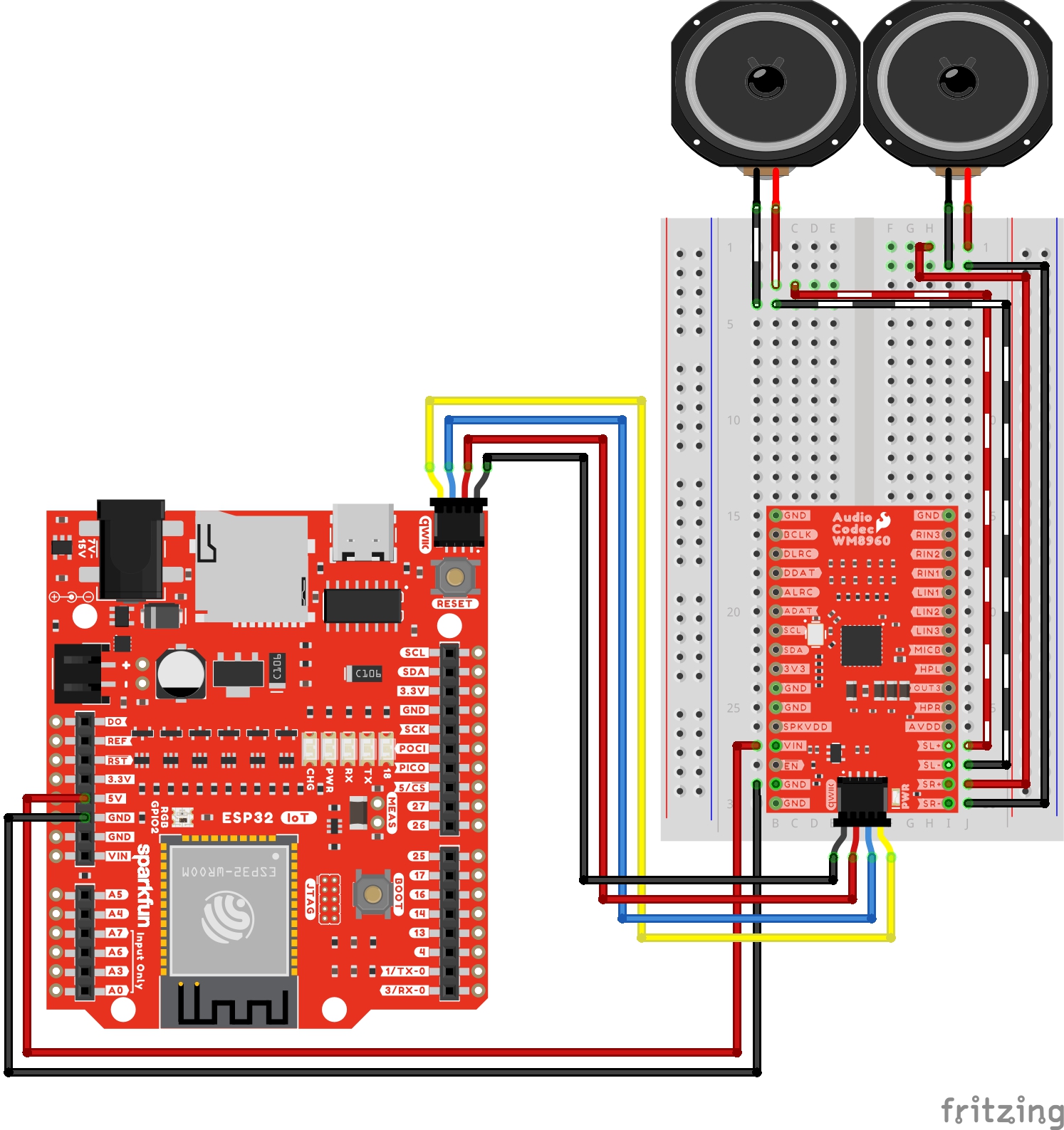
There are a few recommended speaker output configurations from the datasheet to minimize the speaker connection losses due to series resistance and EMI. For a basic setup, we will be using a short wire connection between the audio codec's breakout board and each differential speaker. For those that require long exposed track and want to go the extra mile, users can build an LC filter circuit, add ferrite beads, or shield the wires using PCB ground plane (or Vdd).
The following connection is for connecting speakers to the audio codec's speaker output channels. For simplicity, the table does not include the power and I2C pins.
| Audio Codec - WM8960 | Speakers |
|---|---|
| SL+ | Speaker Left + |
| SL- | Speaker Left - |
| SR+ | Speaker Right + |
| SR+ | Speaker Right - |