Audio Codec Breakout - WM8960 Hookup Guide
 QCPete,
  bboyho
Example 7: Microphone Bias
in this example, we will set the microphone bias voltage and measure the voltage. This is for advanced users looking to add a differential microphone to the microphone input pins.
Hardware Hookup
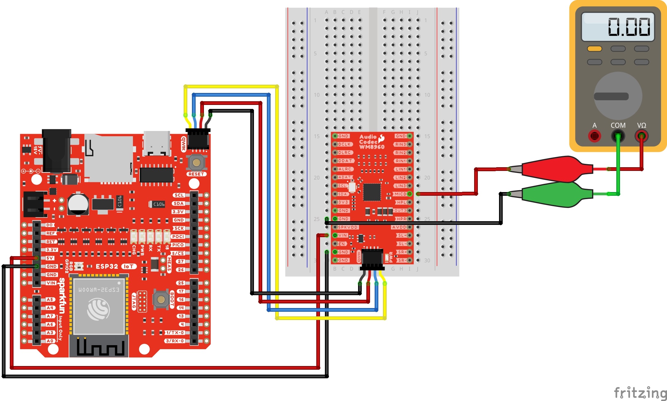
Connect power and I2C. as explained earlier. Then grab a multimeter with alligator clips and M/M jumper wires. Connect the wires to MICBIAS and GND to measure the voltage. Your circuit should look similar to the circuit diagram below.
If you have not already, insert a USB cable into your IoT RedBoard ESP32.
Upload Code
From the menu, select the following: File > Examples > SparkFun WM8960 Arduino Library > Example_07_MicBias. If you have not already, select your Board (in this case the SparkFun ESP32 IoT RedBoard), and associated COM port. Then hit the upload button.
Open the Arduino Serial Monitor and set it to 115200 baud to view the serial output. Measuring the output with a multimeter, the voltage should be similar to the voltages that were set for the MICBIAS pin. After 3 seconds, the pin will be disabled. If you missed the window to measure the MICBIAS voltage, hit the reset button the IoT RedBoard to run the example again.
If you are satisfied with your MICBIAS voltage, head over to example 14 to add a resistor in series with each electret microphone.