Wireless Gesture Controlled Robot
 bboyho
 Introduction
Control the RedBot wirelessly based on the movement of your hand using an accelerometer and XBees!
Required Materials
To follow along with this tutorial, you will need the following materials. You may not need everything though depending on what you have. Add it to your cart, read through the guide, and adjust the cart as necessary.
Tools
You will need wire, wire strippers, a soldering iron, solder, and general soldering accessories.


You Will Also Need
- Glove
- Scissors
- Non-Conductive Thread
Suggested Reading
If you aren’t familiar with the following concepts, we recommend checking out these tutorials before continuing. This tutorial continues on from the Wireless Glove Controller and Wireless RC Robot with Arduino and XBees tutorials. Make sure to check through guides.
Wireless Glove Controller
April 24, 2019
Wireless RC Robot with Arduino and XBees
March 12, 2019
XBee Shield Hookup Guide
Assembly Guide for RedBot with Shadow Chassis
Exploring XBees and XCTU
Experiment Guide for RedBot with Shadow Chassis
Understanding Your Circuit
Wireless Glove Controller
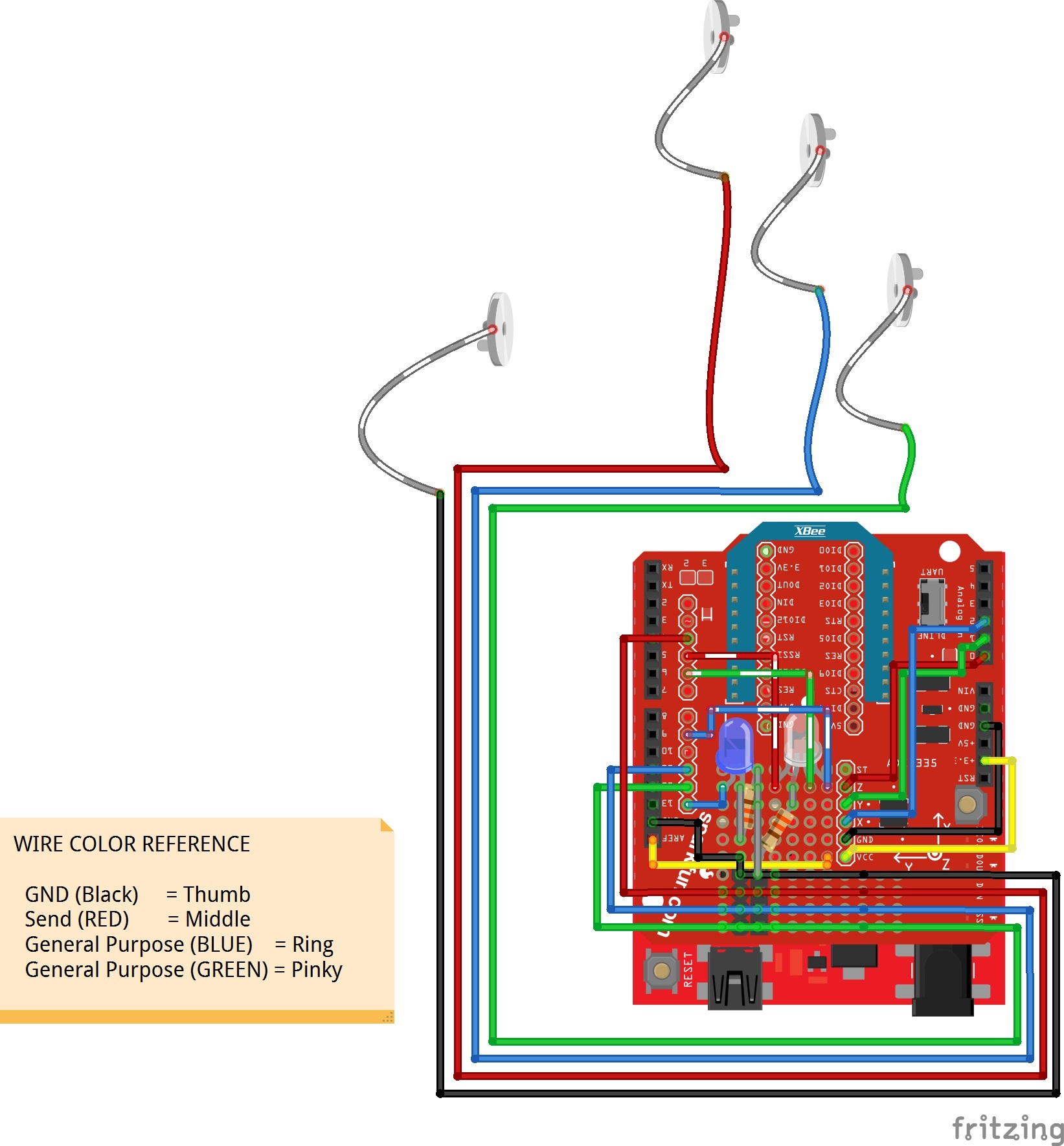
The connection for this project should be the same as the initial circuit. The only differences are the connections for the accelerometer and analog reference pin as shown in the diagram below.
Analog Accelerometer
Since the ADXL335 requires 3.3V, we'll need to connect the VCC pin to 3.3V. To complete the connection for power, you will need to connect GND to GND. Then for the x, y, and z pins, you'll need to connect them to pin 2, 1, and 0, respectively.
Configuring AREF
Since the ADXL335 is 3.3V, we'll need to connect the Arduino's AREF pin to the 3.3V pin. This will configure the reference voltage used for the analog output from the accelerometer. As a result, we can measure smaller voltages (i.e. your 3.3V output) with the best resolution on a 5V Arduino.
Don’t use anything less than 0V or more than 5V for external reference voltage on the AREF pin! If you’re using an external reference on the AREF pin, you must set the analog reference to EXTERNAL before calling analogRead(). Otherwise, you will short together the active reference voltage (internally generated) and the AREF pin, possibly damaging the microcontroller on your Arduino board.
Assembled Shadow Chassis
We'll assume that you have a fully assembled robot with the Shadow Chassis.
Assembly Guide for RedBot with Shadow Chassis
May 28, 2015
Hardware Hookup
Modify the XBee Shield
Adding on to the glove that was built in the Wireless Glove Controller tutorial, remove the tape and disconnect the braided wire from the shield. Then pull the XBee shield off the RedBoard.
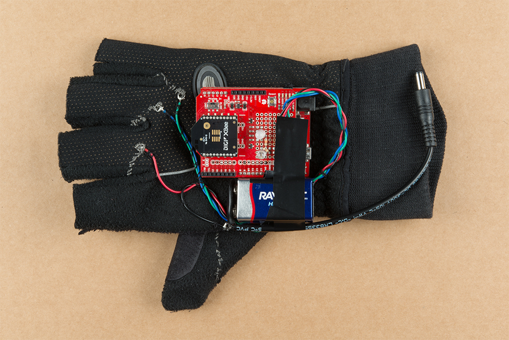
Using the circuit diagram with the accelerometer, solder the ADXL335 breakout board to the shield. In this case, female headers were used with male headers soldered on the breakout. Then strip solid core, hook-up wire and solder them between the pins. If you are following along, your board should look similar to the images below. When you are ready, stack the board back on top of the RedBoard and secure the battery.
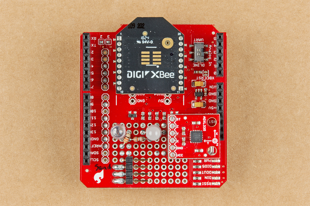 |
 |
| Top View of Components Soldered on XBee Shield | Bottom View with Wires and Jumpers |
Configuring XBees
To configure the XBees, we will be using the XBee Series 1 firmware. It is recommended to configure each XBee using the XBee Explorer USB.
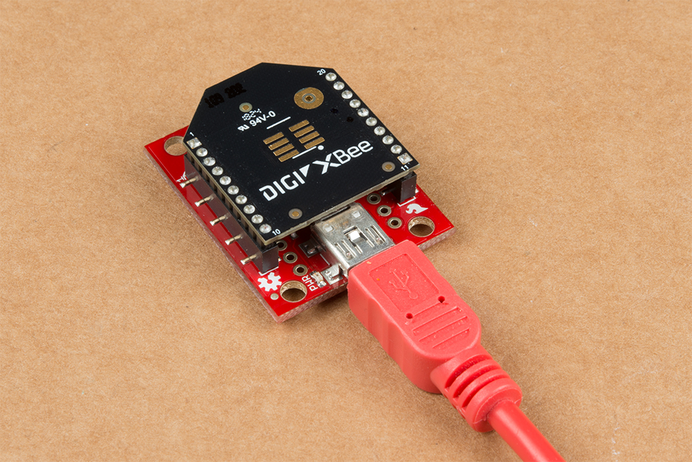
If you have not already, check out the Starting with XCTU section under Exploring XBees and XCTU to configure your XBees.
Exploring XBees and XCTU
March 12, 2015
Point-to-Point Configuration
For simplicity, we will be sending commands with the XBees in transparent mode set for a point-to-point configuration. Make sure to configure each XBee with a unique MY address if there are more than two XBees in your CH and PAN ID. You will then need to adjust the DL address for each respective XBee.
| Setting | Acronym | Transmitting XBee Node 1 (Wireless Glove Controller) | Receiving XBee Node 2 (Robot) |
|---|---|---|---|
| Channel | CH | C | C |
| PAN ID | ID | 3333 | 3333 |
| Destination Address High | DH | 0 | 0 |
| Destination Address Low | DL | 1 | 0 |
| 16-bit Source Address | MY | 0 | 1 |
Setting Up Arduino
RedBot Mainboard
FTDI Drivers
Remember, to program your robot, you will first need to install some FTDI drivers. Follow the steps in How to Install FTDI Drivers to do so. This is also explained in the RedBot Guides.
How to Install FTDI Drivers
June 4, 2013
Arduino Library
Make sure to install the RedBot library as explained in the RedBot Library Quick Reference. You'll also find the quick overview of the RedBot Library, classes, methods, and variables.
Example
Wireless Glove Code
In this part of the example, we'll have the glove send a character when the thumb and middle finger make contact. As long as the two fingers have contact, the robot will move forward, forward-left, back, or forward -right based on the orientation of your hand. When the custom button is not pressed, the buzzer will make a familiar 8-bit sound when waving your hand or "jabbing" the air. The RGB LED will light up based on the mode and orientation of the hand.
Copy the code, paste it into the Arduino IDE, select your board (Arduino/Genuino Uno), and COM port. Then upload the code to the glove.
language:c
// We'll use SoftwareSerial to communicate with the XBee:

#include <SoftwareSerial.h>

//For Atmega328P's
// XBee's DOUT (TX) is connected to pin 2 (Arduino's Software RX)
// XBee's DIN (RX) is connected to pin 3 (Arduino's Software TX)
SoftwareSerial XBee(2, 3); // RX, TX

//For Atmega2560, ATmega32U4, etc.
// XBee's DOUT (TX) is connected to pin 10 (Arduino's Software RX)
// XBee's DIN (RX) is connected to pin 11 (Arduino's Software TX)
//SoftwareSerial XBee(10, 11); // RX, TX

//set analog read pins
const int xPin = 2;//x=A2
const int yPin = 1;//y=A1
const int zPin = 0;//z=A0

//read the analog values from the accelerometer
int xRead = analogRead(xPin);
int yRead = analogRead(yPin);
int zRead = analogRead(zPin);

//LED Status Indicator
int ledR = 5;//hardware PWM
int ledG = 6;//hardware PWM
int ledB = 9; //hardware PWM

//Accelerate Button
#define ACCELERATE_BUTTON 4 // Pin used for accelerate button
const int ledPin1 = 13;  //LED on the push button

boolean current_buttonACCELERATE_State;

void setup() {
  // initialize the digital pins as an output for LEDs
  pinMode(ledPin1, OUTPUT);
  pinMode(ledR, OUTPUT);
  pinMode(ledG, OUTPUT);
  pinMode(ledB, OUTPUT);

  analogReference(EXTERNAL);//reference 3.3V since using 3.3V accelerometer

  pinMode(ACCELERATE_BUTTON, INPUT_PULLUP); // Enable pullup resistor for accelerate button D2

  // Set up both ports at 9600 baud. This value is most important
  // for the XBee. Make sure the baud rate matches the config
  // setting of your XBee.
  XBee.begin(9600);

  for (int i = 0; i < 3; i++) {
    digitalWrite(ledPin1, HIGH);
    delay(50);
    digitalWrite(ledPin1, LOW);
    delay(50);
  }
  sequenceTest();//visually initialization

  Serial.begin(9600);
  Serial.println("Wireless XBee Glove Controller Initialized");
}

void loop() {

  current_buttonACCELERATE_State = digitalRead(ACCELERATE_BUTTON);


  //Read accelerometer axes using through the ADC
  //Note: Check description at top for results based on Accelerometer Mode's Features
  xRead = analogRead(xPin);
  Serial.print("Analog xPin (A2) = ");
  Serial.println(xRead);
  yRead = analogRead(yPin);
  Serial.print("Analog yPin (A1) = ");
  Serial.println(yRead);
  zRead = analogRead(zPin);
  Serial.print("Analog zPin (A2) = ");
  Serial.println(zRead);
  Serial.println("");
  //delay(500); //slow down the print to read, adjust as necessary for testing

  if (current_buttonACCELERATE_State == LOW) {
    if (xRead < 430) {
      Serial.print("Drive Forward, xRead = ");
      Serial.println(xRead);
      Serial.println('A');

      XBee.write('A');
      greenON();
    }
    else if (xRead > 590) {
      Serial.print("Drive Backward, xRead = ");
      Serial.println(xRead);
      Serial.println('C');

      XBee.write('C');
      blueON();
    }
    else if (yRead > 590) {
      Serial.print("Drive Forward Right, yRead = ");
      Serial.println(yRead);
      Serial.println('B');

      XBee.write('B');
      cyanON();
    }
    else if (yRead < 430) {
      Serial.print("Drive Forward Left, yRead = ");
      Serial.println(yRead);
      Serial.println('D');

      XBee.write('D');
      cyanON();
    }
    else {
      Serial.println("Coast");
      Serial.println('J');

      XBee.write('J');
      magentaON();
    }

  }
  else {
    if (xRead > 670) {

      Serial.println("Coin Sound, xRead = ");
      Serial.println(xRead);
      Serial.println('X');

      XBee.write('X');
      allOFF();
      delay(50);
      yellowON();
      delay(50);
    }
    if (zRead < 400) {

      Serial.println("Fireball Sound, zRead = ");
      Serial.println(zRead);
      Serial.println('Y');

      XBee.write('Y');
      redON();
      delay(50);
      allOFF();
      delay(50);
      redON();
      delay(50);
      allOFF();
      delay(50);

    }
    else {
      Serial.println("Stop");
      Serial.println('K');

      XBee.write('K');
      redON();
      delay(750);
    }
  }

  //show that we are sending a character
  digitalWrite(ledPin1, HIGH);
  delay(50);
  digitalWrite(ledPin1, LOW);
  delay(50);
}//end loop

void allOFF() {
  analogWrite(ledR, 0);
  analogWrite(ledG, 0);
  analogWrite(ledB, 0);
}

void allON() {
  analogWrite(ledR, 150);
  analogWrite(ledG, 255);
  analogWrite(ledB, 255);
}

void redON() {
  analogWrite(ledR, 255);
  analogWrite(ledG, 0);
  analogWrite(ledB, 0);
}

void magentaON() {
  analogWrite(ledR, 150);
  analogWrite(ledG, 0);
  analogWrite(ledB, 255);
}

void blueON() {
  analogWrite(ledR, 0);
  analogWrite(ledG, 0);
  analogWrite(ledB, 255);
}

void cyanON() {
  analogWrite(ledR, 0);
  analogWrite(ledG, 255);
  analogWrite(ledB, 255);
}

void greenON() {
  analogWrite(ledR, 0);
  analogWrite(ledG, 255);
  analogWrite(ledB, 0);
}

void yellowON() {
  analogWrite(ledR, 150);
  analogWrite(ledG, 255);
  analogWrite(ledB, 0);
}

void sequenceTest() {
  redON();
  delay(50);
  magentaON();
  delay(50);
  blueON();
  delay(50);
  cyanON();
  delay(50);
  greenON();
  delay(50);
  yellowON();
  delay(50);
  allON();
  delay(50);
  allOFF();
  delay(50);
}
Receiving XBee Robot Code
The commands to control the RedBot should be the same code that was used in the last example of the Wireless RC Robot with Arduino and XBees tutorial. Head over to Experiment 4.2: Adding Audio with the ATmega328P to upload code to the RedBot mainboard if you have not already.
What You Should See
After uploading, touch the metal snap pins between your thumb and middle finger to move the robot forward-left, forward, forward-right, or backward. The RGB LED will light up based on the orientation of your hand. Separate your fingers and punch the air as if there is a question mark block above you to hear coin sound effect! Wave your hand to see if you can make a fireball sound effect!
Resources and Going Further
Need some inspiration for your next project? Check out some of these related tutorials to add more functionality for your wireless glove!