Motion Controlled Wearable LED Dance Harness
 bboyho
Calibrating the Accelerometer
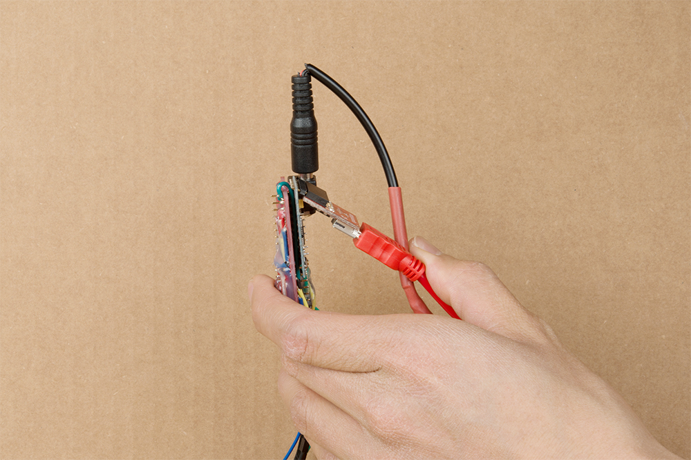
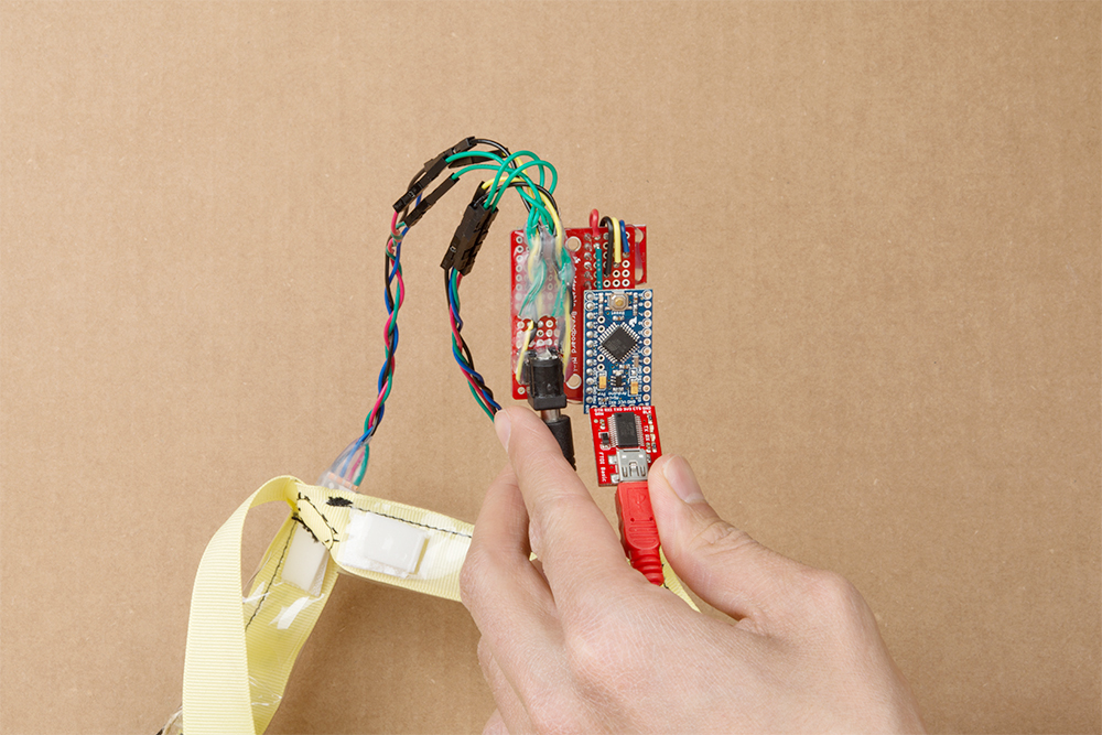
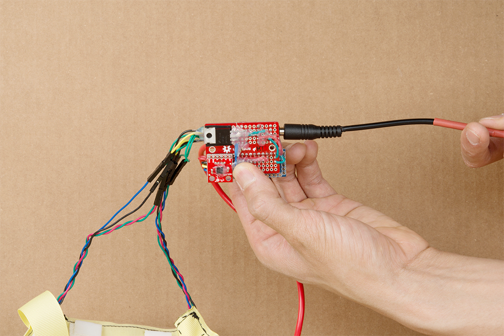
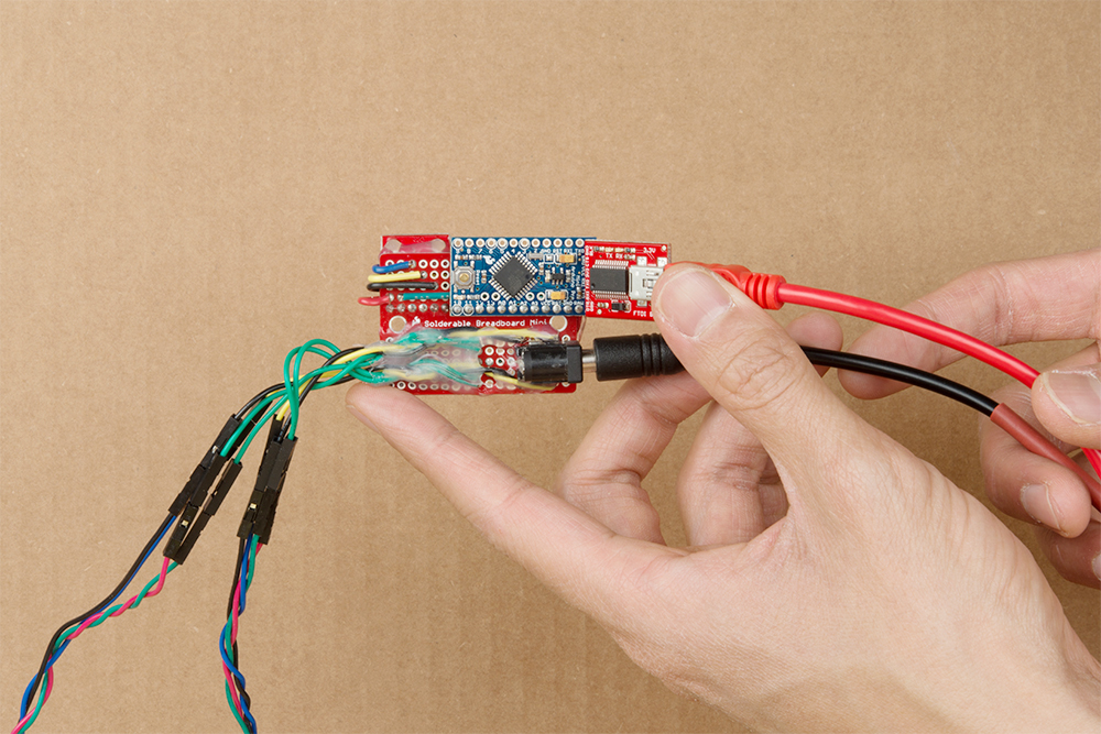
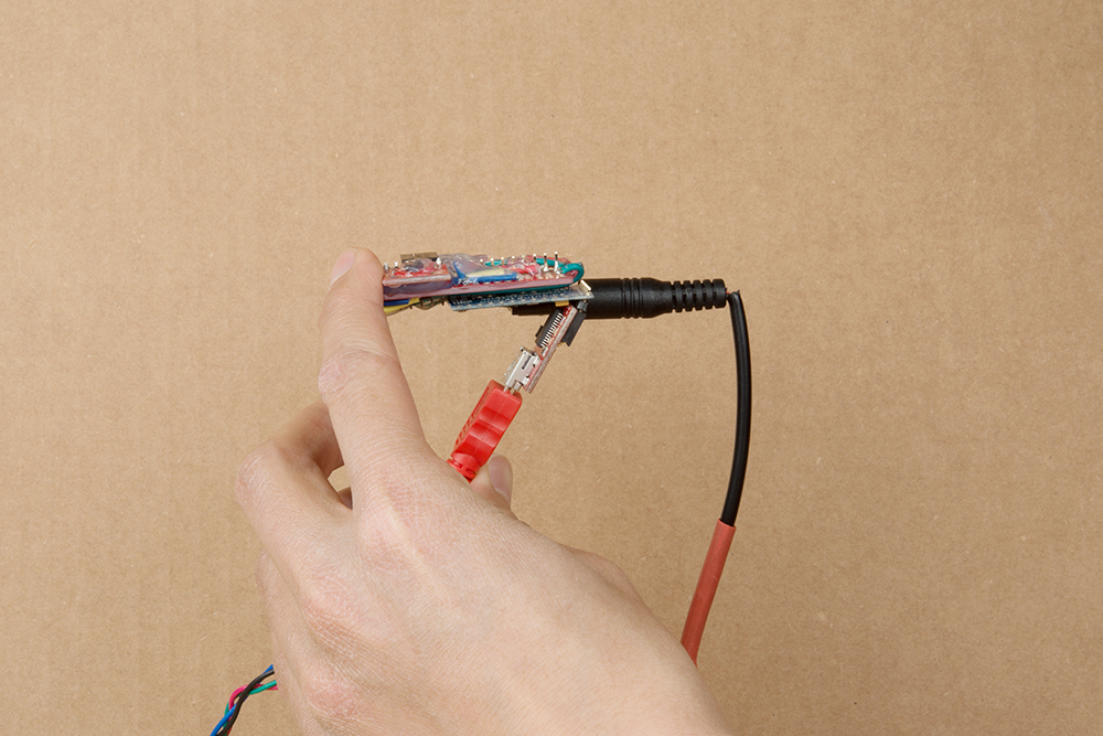
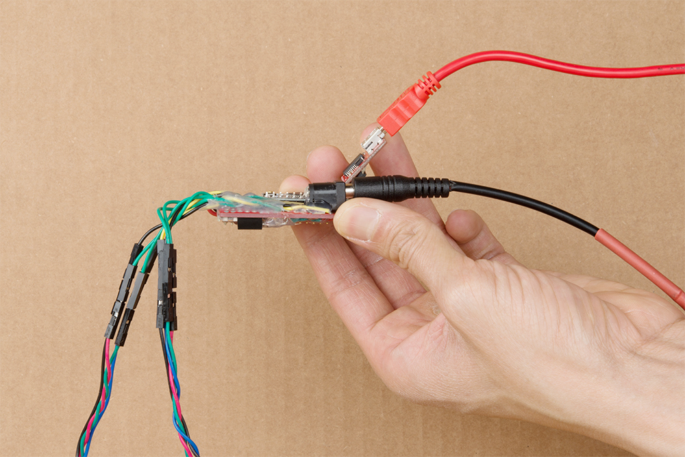
There are some slight tolerances so the output will not be exactly the same number for each axis. To calibrate each low-G accelerometer, we simply use gravity! Initial tests of the circuit were done on a breadboard and wires before soldering the circuit to a prototyping board.

Initial Testing
The code in MinionAccelerometerV2.0.ino was used to calibrate the accelerometer after soldering the circuit and observe raw sensor readings when the dancer is:
- Standing/Right Side Up
- Upside Down
- On the Right Side
- On the Left Side
- On the Stomach
- On the Back
I decided to have the LEDs on when the dancer is right-side up, blinking when upside down, off when on their sides, and fading in/out when on their back/stomach. Feel free to adjust the effects as necessary for your application.
Head to the folder containing the example code ( ... Motion-Controlled-Wearable-LED-Dance-Harness > Firmware > Arduino > MinionAccelerometerV2.0.ino ) and open it up using the Arduino IDE. Make sure to select the Arduino Pro or Pro Mini as the board, ATmega328P (3.3V/8MHz) as the processor, and the COM port that the FTDI enumerated on. Then upload the code to the Arduino. After uploading, open the serial monitor to check out the raw output for each axis.
+X Component Readings Standing/Right Side Up
Angle the motion controller so that the ADXL335's ↑ X silkscreen is pointing up to determine when the dancer is standing or right side up. The example code has the LEDs staying on.
 |
 |
| ↑ X Silkscreen is Pointing Up | Dancer Right Side Up Demonstrating Toprocks with the Harness |
When the ↑ X is pointing up, you will get a value close to about ~600. The other values will read an average of ~500. We'll want to know the maximum when this happens to control the LEDs so the sensor will need to be tilted slightly to verify.
language:bash
Start Reading Accelerometer
Analog xPin (A0) = 589
Analog yPin (A1) = 512
Analog zPin (A2) = 481

Analog xPin (A0) = 610
Analog yPin (A1) = 514
Analog zPin (A2) = 510

Analog xPin (A0) = 608
Analog yPin (A1) = 515
Analog zPin (A2) = 509
In this case, 610 appeared to be the maximum value for X while the sensor is not moving.
-X Component Readings Upside Down
Angle the motion controller so that the ADXL335's ↑ X silkscreen is pointing down to determine when the dancer is upside down. The example code has the LEDs blinking.
 |
 |
| ↑ X Silkscreen is Pointing Down | Dancer Upside Down Demonstrating a Headstand with the Harness |
When the ↑ X silkscreen is pointing down, you will get a value close to about ~400. The other values will read an average of ~500 again. We will need to tilt the sensor slightly to verify the minimum.
language:bash
Analog xPin (A0) = 409
Analog yPin (A1) = 502
Analog zPin (A2) = 501

Analog xPin (A0) = 402
Analog yPin (A1) = 504
Analog zPin (A2) = 497

Analog xPin (A0) = 403
Analog yPin (A1) = 506
Analog zPin (A2) = 499
In this case, 402 appeared to be the minimum value for X when the sensor is not moving.
+Y Component Readings On the Right Side
Angle the motion controller so that the ADXL335's ← Y silkscreen is pointing up to determine when the dancer is on their right side. The example code has the LEDs turning off.
 |
 |
| ← Y Silkscreen is Pointing Up | Dancer On Their Right Side Demonstrating a CC with the Harness |
When the ← Y silkscreen is pointing up, you will get a value close to about ~612. The other values will read an average of ~500. Tilt the sensor slightly to verify the maximum.
language:bash
Analog xPin (A0) = 515
Analog yPin (A1) = 610
Analog zPin (A2) = 517

Analog xPin (A0) = 515
Analog yPin (A1) = 612
Analog zPin (A2) = 515

Analog xPin (A0) = 514
Analog yPin (A1) = 611
Analog zPin (A2) = 517
In this case, 612 appeared to be the maximum value for Y when the sensor is not moving.
-Y Component Readings On the Left Side
Angle the motion controller to its side so that the ADXL335's ← Y silkscreen is pointing down to determine when the dancer is on their left side. The example code has the LEDs turn off as well.
 |
 |
| ← Y Silkscreen is Pointing Down | Dancer On Their Left Side Demonstrating a CC with the Harness |
When the ← Y silkscreen is pointing down, you will get a value close to about ~400. The other values will read an average of ~500 again. We will tilt the sensor once again slightly to verify the minimum.
language:bash
Analog xPin (A0) = 506
Analog yPin (A1) = 403
Analog zPin (A2) = 515

Analog xPin (A0) = 512
Analog yPin (A1) = 402
Analog zPin (A2) = 514

Analog xPin (A0) = 508
Analog yPin (A1) = 404
Analog zPin (A2) = 515
In this case, 402 appeared to be the minimum value for Y when the sensor is not moving.
+Z Component Readings On the Back
Lay the sensor so that the ADXL335's • Z silkscreen is facing up to determine when the dancer is on their back. The example code has the LEDs fading in and out.
 |
 |
| • Z Silkscreen is Facing Up | Dancer On Their Back |
When the • Z silkscreen is facing up, you will get a value close to about ~600. The other values will read an average of ~500 again. Tilt the sensor slightly to verify the maximum.
language:bash
Analog xPin (A0) = 507
Analog yPin (A1) = 509
Analog zPin (A2) = 609

Analog xPin (A0) = 511
Analog yPin (A1) = 509
Analog zPin (A2) = 611

Analog xPin (A0) = 514
Analog yPin (A1) = 506
Analog zPin (A2) = 609
In this case, 611 appeared to be the maximum value for Z when the sensor is not moving.
-Z Component Readings On the Stomach
Lay the sensor so that the ADXL335's • Z silkscreen is facing down to determine when the dancer is on their stomach. The example code has the LEDs fading in and out.
 |
 |
| • Z Silkscreen is Facing Down | Dancer On Their Stomach |
When the • Z silkscreen is facing down, you will get a value close to about ~400. The other values will read an average of ~500 again. Tilt the sensor slightly to verify the minimum.
language:bash
Analog xPin (A0) = 494
Analog yPin (A1) = 516
Analog zPin (A2) = 406

Analog xPin (A0) = 495
Analog yPin (A1) = 515
Analog zPin (A2) = 403

Analog xPin (A0) = 495
Analog yPin (A1) = 514
Analog zPin (A2) = 404
In this case, 403 appeared to be the minimum value for Z when the sensor is not moving.
Adjusting Boundaries for Detecting Orientation
We'll need to tweak those values to make sure that the accelerometer used matches the setup. Using the values obtained from calibration, the condition statements to control the LEDs were adjusted from the following lines of code:
language:c
  //X-X-X-X-X-X-X | READ xAxis | X-X-X-X-X-X-X
  //LEDs ON
  if (xRead > 605) {
  //...

  //LEDs Blinking
  if (xRead < 411) {
  //...

  //Y-Y-Y-Y-Y-Y-Y | Read yAxis | Y-Y-Y-Y-Y-Y-Y
  //LEDs OFF
  if (yRead > 607 || yRead < 409 ) {
  //...

  //Z-Z-Z-Z-Z-Z-Z | read zAxis | Z-Z-Z-Z-Z-Z-Z
  //
  if (zRead > 610 || zRead < 425) {
  //...
To the maximum and minimum values obtained for each component:
language:c
  //X-X-X-X-X-X-X | READ xAxis | X-X-X-X-X-X-X
  //LEDs ON
  if (xRead > 610) {
  //...

  //LEDs Blinking
  if (xRead < 402) {
  //...

  //Y-Y-Y-Y-Y-Y-Y | Read yAxis | Y-Y-Y-Y-Y-Y-Y
  //LEDs OFF
  if (yRead > 612 || yRead < 402) {
  //...

  //Z-Z-Z-Z-Z-Z-Z | read zAxis | Z-Z-Z-Z-Z-Z-Z
  //
  if (zRead > 611 || zRead < 403) {
  //...
Whew. That was a bit tedious. We're not done yet though!