Motion Controlled Wearable LED Dance Harness
 bboyho
Understanding Your Circuit
Initial Circuit
For the scope of this tutorial, we will be focusing on the motion controller and using the LED strips and custom harness from the previous tutorial. Green and red were chosen to make yellow from the primary colors. A low-G, triple-axis, analog accelerometer (ADXL335) was added to sense the orientation of a dancer. A 3.3V Arduino was added to read the analog sensor data and control the LED strips based on the readings. Since the LED strips are powered at 9V and require more current than the Arduino's I/O pins can source, an n-channel MOSFET was chosen to safely control the LED strips. A 10kΩ pull-down resistor was added between the gate and ground so that the transistor is not floating.
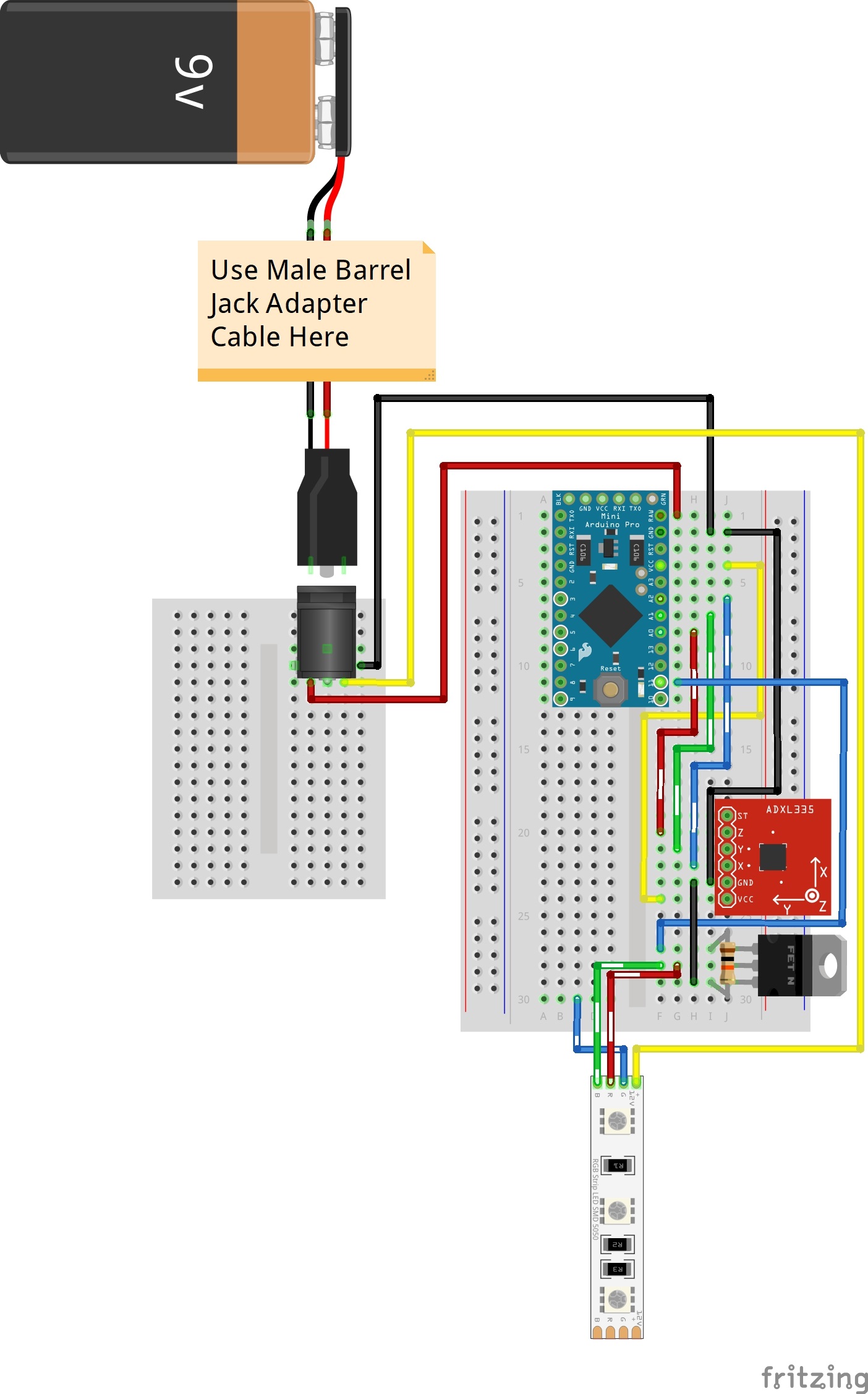
A 9V battery and custom made motion controller were used for each harness. Keep in mind that a 9V battery is not able to power all three colors simultaneously. However, using two colors was sufficient enough for the project and performance.
Complete Circuit
After successful tests on a breadboard, the circuit was condensed and soldered to a mini-solderable breadboard. Components were added to both sides of the breadboard to take advantage of the space provided. The front view is shown below to illustrate the circuit. Keep in mind that the transparent components are mirrored images of the Arduino Pro Mini and barrel jack. The top view for each of these components would be facing outward on the other side. Additionally, the wires are soldered between the boards.
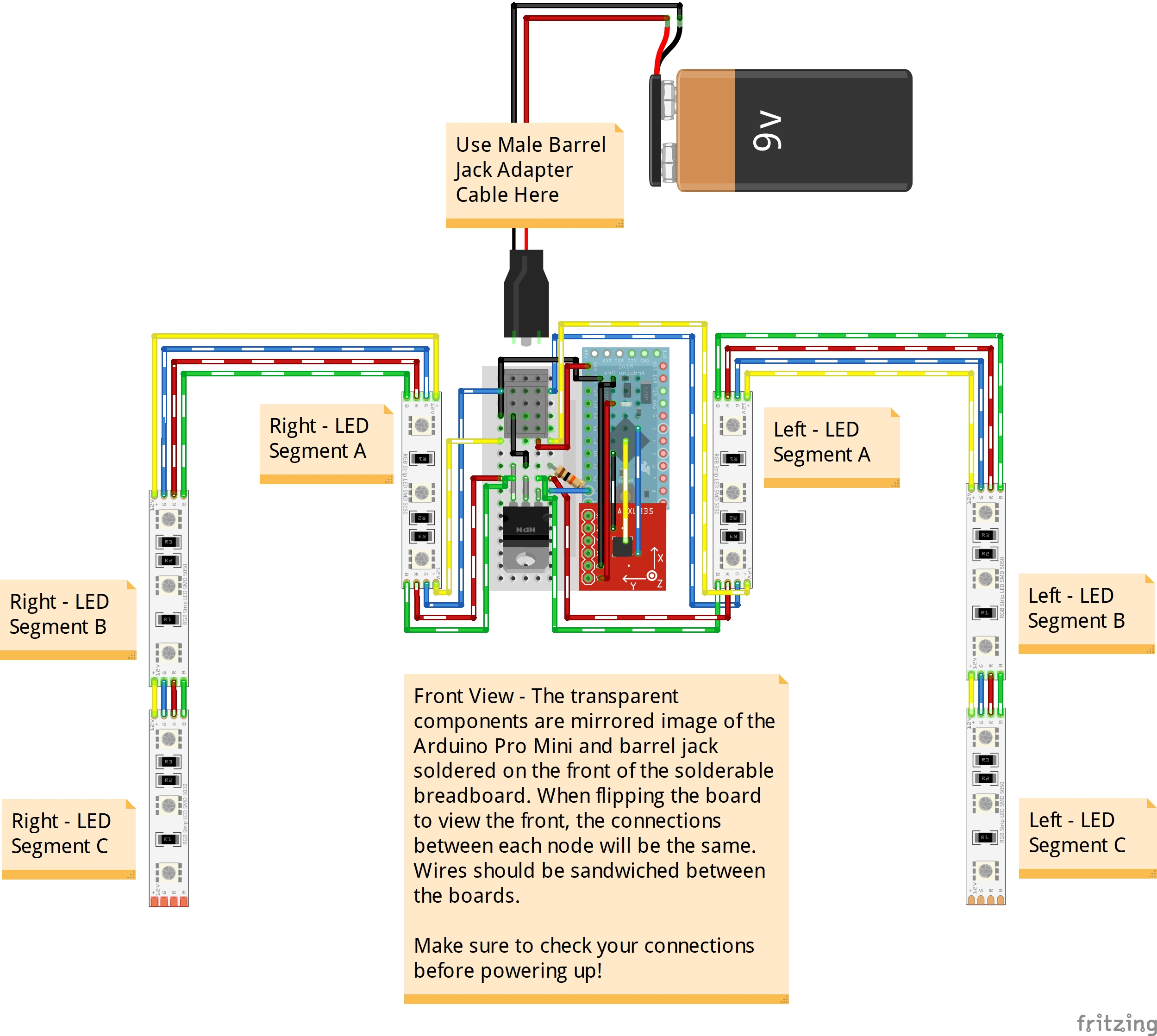
The back view is shown below to illustrate the circuit. Again, the transparent components are mirrored images of the accelerometer, resistor, and n-channel MOSFET. The top view for each of these components would be facing outward on the other side.
