Motion Controlled Wearable LED Dance Harness
 bboyho
 Introduction
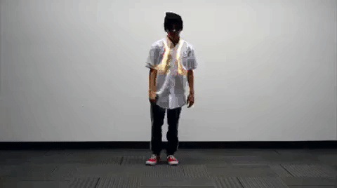
Continuing on from the last time, we are going to add an accelerometer to detect basic movements and control a 12V non-addressable LED strip for Mark III! Make your LEDs breathe by fading in and out when laying on the floor. Turn off the LEDs when moving to your side. Or make the LEDs blink in a headstand!
Required Materials
To follow along with this tutorial, you will need the following materials listed below to build one motion controller. This is assuming that you have already soldered wires to LED strips and a harness from the first tutorial. You may not need everything, depending on what you have. Add it to your cart, read through the guides, and adjust the cart as necessary.
Tools
You will need a soldering iron, solder, general soldering accessories, and tools to work with wire.


Weller WE1010 Soldering Station
TOL-14734You will also need:
- Scissors
- Electrical Tape
- Hot glue gun
- String
Suggested Reading
If you do not have a harness or LED strips prepared, make sure you start with this tutorial before continuing. This tutorial builds on the project that was used in the previous tutorial.
Prototype Wearable LED Dance Harness
If you aren’t familiar with the following concepts, we also recommend checking out these tutorials before continuing.
How to Power a Project
Accelerometer Basics
How to Install FTDI Drivers
Using the Arduino Pro Mini 3.3V
Transistors
Planning a Wearable Electronics Project
Understanding Your Circuit
Initial Circuit
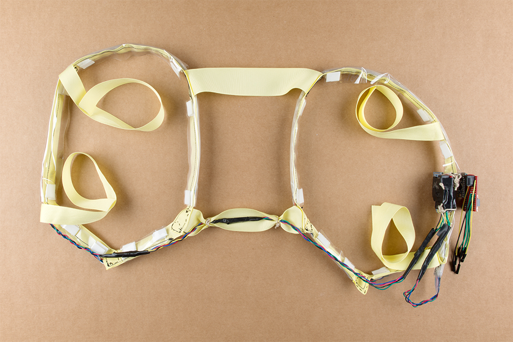
For the scope of this tutorial, we will be focusing on the motion controller and using the LED strips and custom harness from the previous tutorial. Green and red were chosen to make yellow from the primary colors. A low-G, triple-axis, analog accelerometer (ADXL335) was added to sense the orientation of a dancer. A 3.3V Arduino was added to read the analog sensor data and control the LED strips based on the readings. Since the LED strips are powered at 9V and require more current than the Arduino's I/O pins can source, an n-channel MOSFET was chosen to safely control the LED strips. A 10kΩ pull-down resistor was added between the gate and ground so that the transistor is not floating.
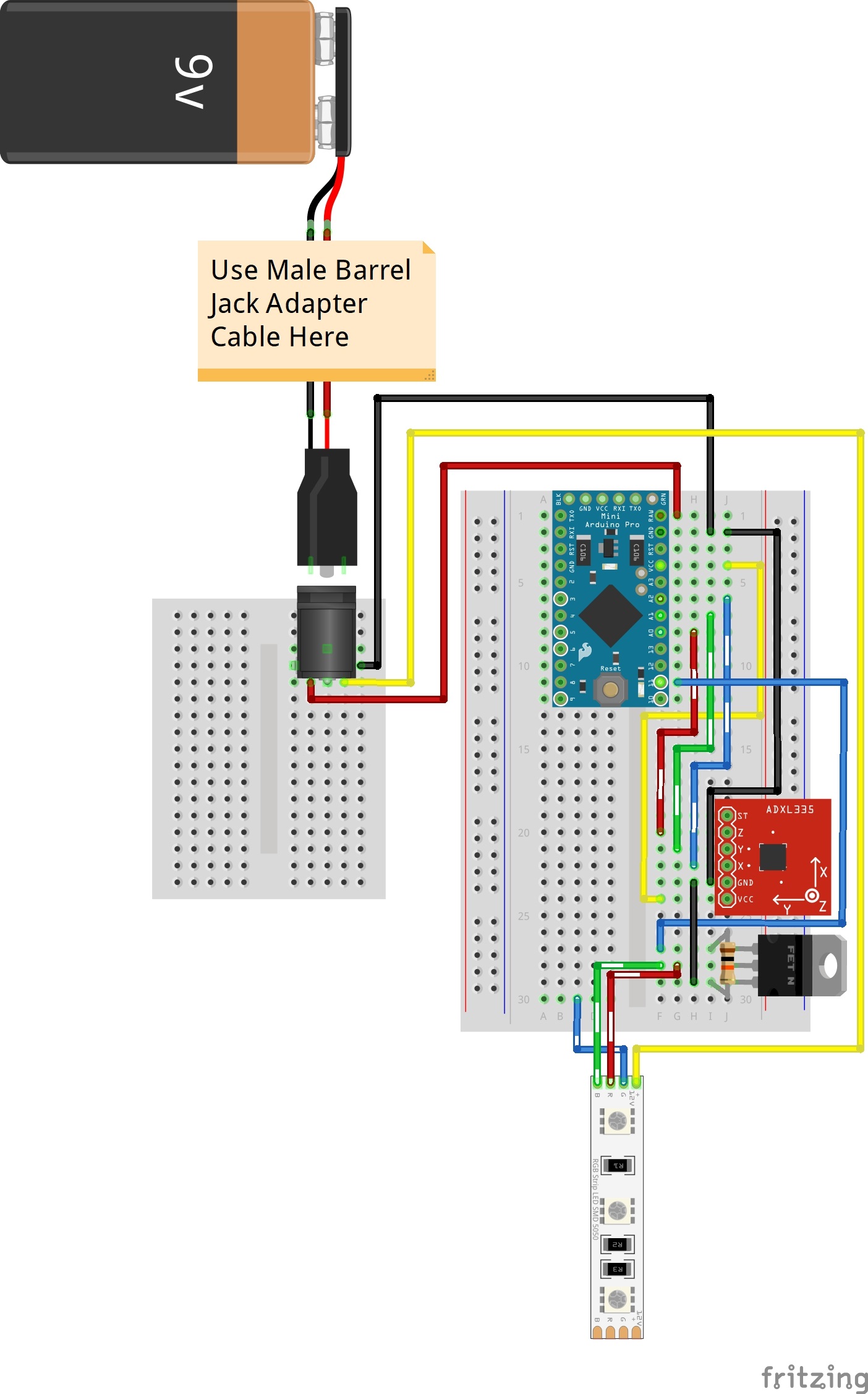
A 9V battery and custom made motion controller were used for each harness. Keep in mind that a 9V battery is not able to power all three colors simultaneously. However, using two colors was sufficient enough for the project and performance.
Complete Circuit
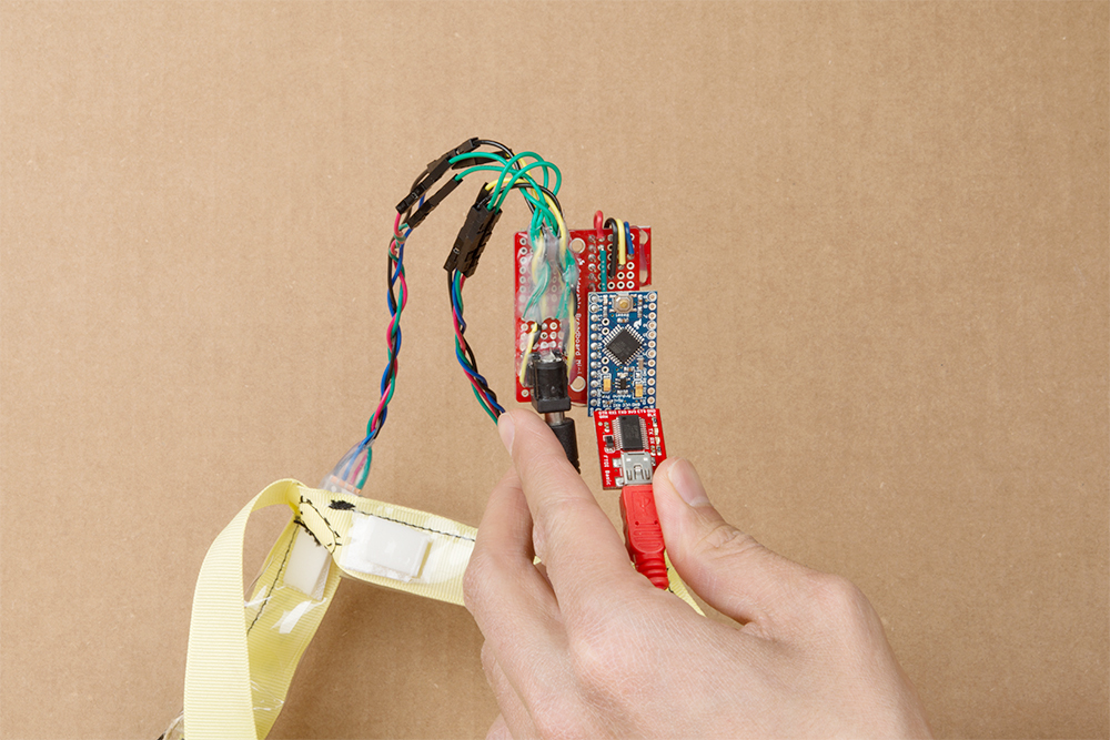
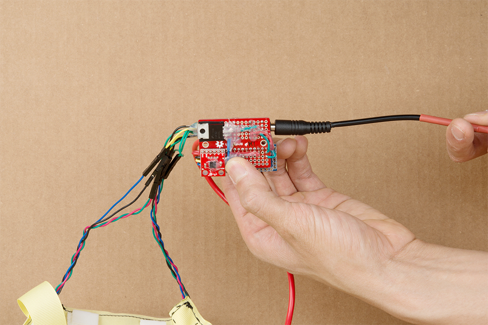
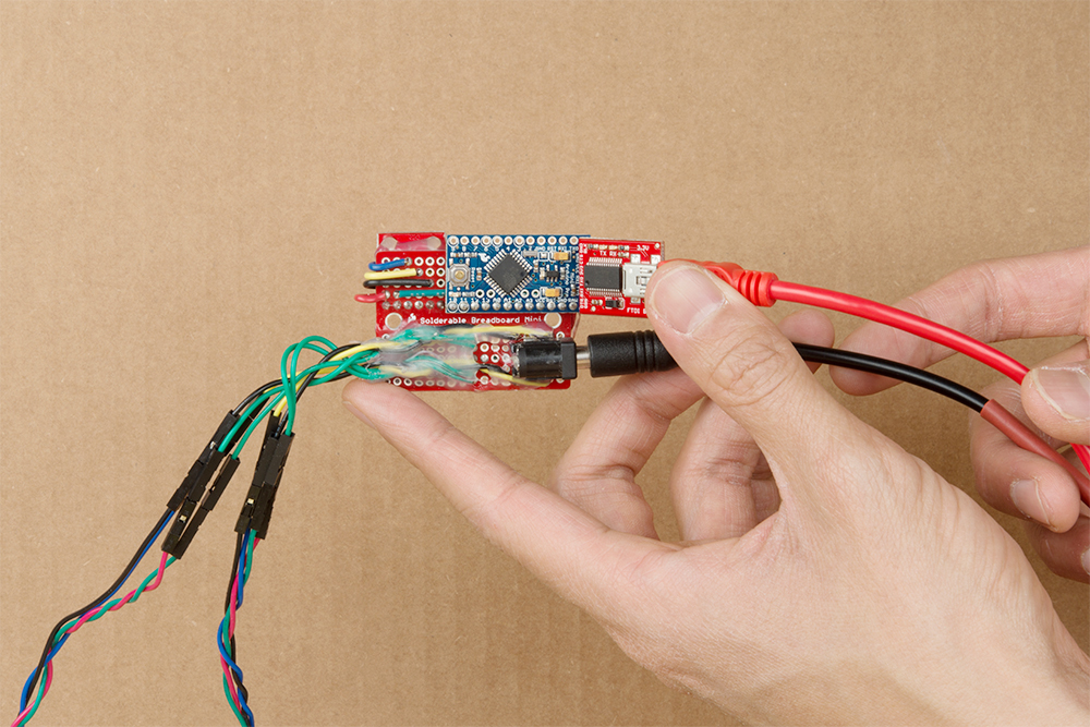
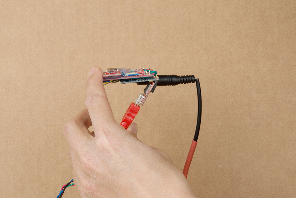
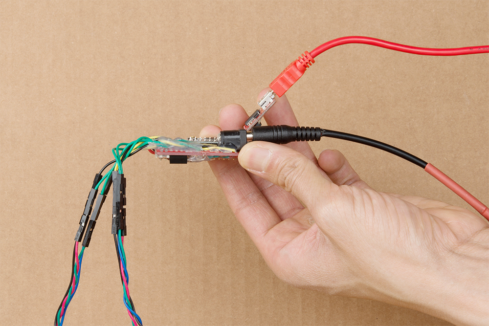
After successful tests on a breadboard, the circuit was condensed and soldered to a mini-solderable breadboard. Components were added to both sides of the breadboard to take advantage of the space provided. The front view is shown below to illustrate the circuit. Keep in mind that the transparent components are mirrored images of the Arduino Pro Mini and barrel jack. The top view for each of these components would be facing outward on the other side. Additionally, the wires are soldered between the boards.
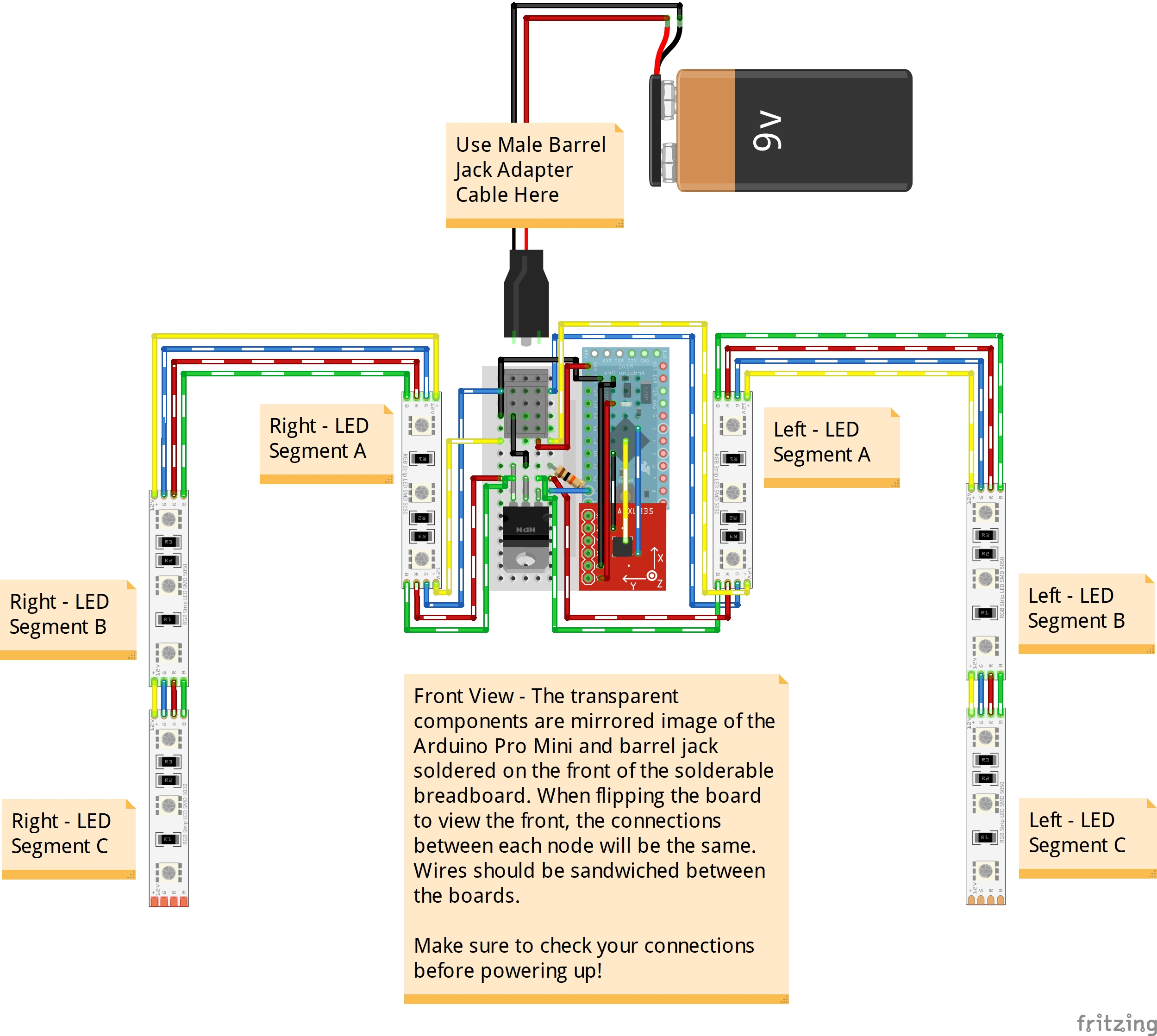
The back view is shown below to illustrate the circuit. Again, the transparent components are mirrored images of the accelerometer, resistor, and n-channel MOSFET. The top view for each of these components would be facing outward on the other side.

Hardware Hookup
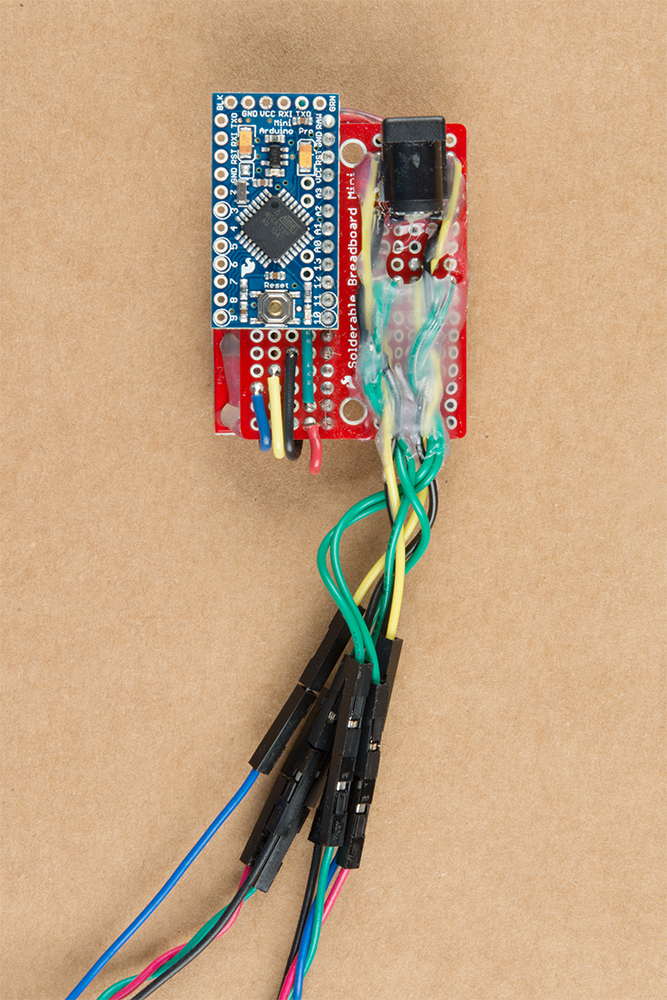
When soldering the n-channel MOSFET to the solderable breadboard, a piece of electrical tape was added to the exposed drain on the back of the MOSFET. While it was not necessary, it was a reminder to not solder any circuits under the exposed drain where it could make contact via the plated through holes.
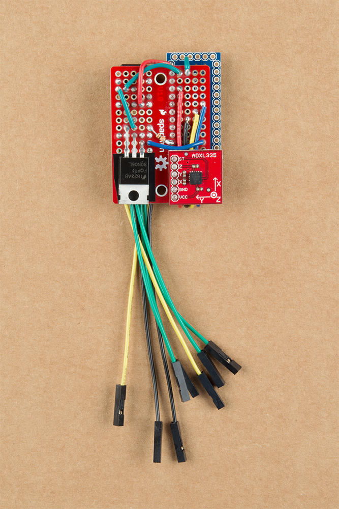
If you have not already, solder straight male headers on your Arduino Pro Mini 3.3V/8MHz. Also, make sure to solder straight headers to your ADXL335 accelerometer. Then solder the pieces together on the solderable breadboard and create the same connections with stripped wire as explained earlier. Wires terminated with a female header were used to connect to the LED strip's male headers. There are a lot of connections that need to be soldered so we'll just skip ahead to the completed circuit. Your circuit will look similar to the images below.
 |
 |
| Front View | Back View |
Securing the Controller
Secure the Wires
Add some hot glue to secure the wires and components to the board. Special attention was given to the sensitive joints where the wires or components may break.
 |
 |
| Front View Secured with Hot Glue | Back View Secured with Hot Glue |
Secure the Wires and Motion Controller To Harness
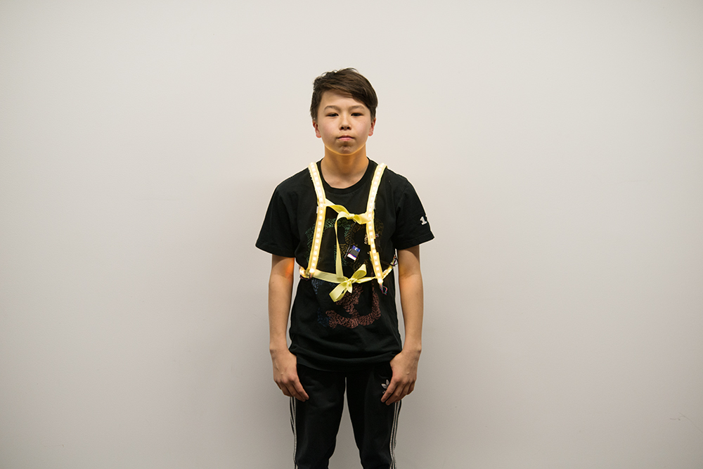
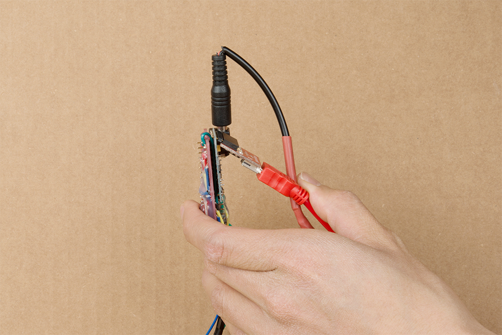
To secure the wires, we follow the same process as last time. The only difference is that we are using a motion controller instead of the power adapter. Plug in the jumper wires of your choice and add some electrical tape to secure the headers. Wrap some tape around the motion controller to protect and secure the board further. To be consistent with the code, make sure that the back of the board is facing toward the dancer and the wires are extending down the harness as shown in the image. A second board was placed in the image for reference.

Once again, the user can slide the harness on like a backpack, tie the ribbons across the chest and waist, and plug in the battery to test. The image below shows the battery just before being secured to the ribbon located above the motion controller. To diffuse, we'll added a translucent button-up shirt over the LEDs.
Example Code
To read the sensor readings and control the LEDs, we'll need to program the Arduino. Head over to the GitHub repository to download the project code. Make sure to download and unzip the contents in order to view the example code located in the ... Motion-Controlled-Wearable-LED-Dance-Harness > Firmware > Arduino folder.
Calibrating the Accelerometer
There are some slight tolerances so the output will not be exactly the same number for each axis. To calibrate each low-G accelerometer, we simply use gravity! Initial tests of the circuit were done on a breadboard and wires before soldering the circuit to a prototyping board.

Initial Testing
The code in MinionAccelerometerV2.0.ino was used to calibrate the accelerometer after soldering the circuit and observe raw sensor readings when the dancer is:
- Standing/Right Side Up
- Upside Down
- On the Right Side
- On the Left Side
- On the Stomach
- On the Back
I decided to have the LEDs on when the dancer is right-side up, blinking when upside down, off when on their sides, and fading in/out when on their back/stomach. Feel free to adjust the effects as necessary for your application.
Head to the folder containing the example code ( ... Motion-Controlled-Wearable-LED-Dance-Harness > Firmware > Arduino > MinionAccelerometerV2.0.ino ) and open it up using the Arduino IDE. Make sure to select the Arduino Pro or Pro Mini as the board, ATmega328P (3.3V/8MHz) as the processor, and the COM port that the FTDI enumerated on. Then upload the code to the Arduino. After uploading, open the serial monitor to check out the raw output for each axis.
+X Component Readings Standing/Right Side Up
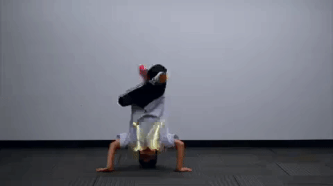
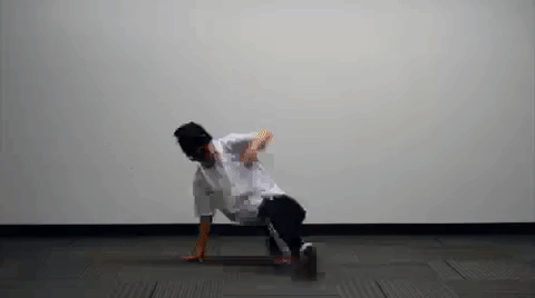
Angle the motion controller so that the ADXL335's ↑ X silkscreen is pointing up to determine when the dancer is standing or right side up. The example code has the LEDs staying on.
 |
 |
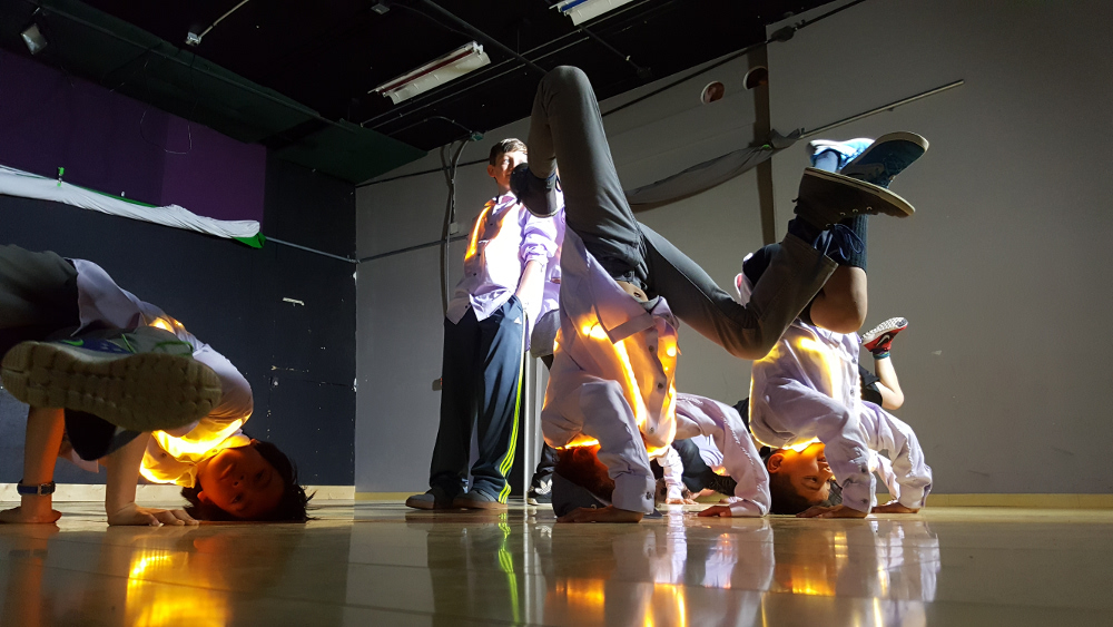
| ↑ X Silkscreen is Pointing Up | Dancer Right Side Up Demonstrating Toprocks with the Harness |
When the ↑ X is pointing up, you will get a value close to about ~600. The other values will read an average of ~500. We'll want to know the maximum when this happens to control the LEDs so the sensor will need to be tilted slightly to verify.
language:bash
Start Reading Accelerometer
Analog xPin (A0) = 589
Analog yPin (A1) = 512
Analog zPin (A2) = 481

Analog xPin (A0) = 610
Analog yPin (A1) = 514
Analog zPin (A2) = 510

Analog xPin (A0) = 608
Analog yPin (A1) = 515
Analog zPin (A2) = 509
In this case, 610 appeared to be the maximum value for X while the sensor is not moving.
-X Component Readings Upside Down
Angle the motion controller so that the ADXL335's ↑ X silkscreen is pointing down to determine when the dancer is upside down. The example code has the LEDs blinking.
 |
 |
| ↑ X Silkscreen is Pointing Down | Dancer Upside Down Demonstrating a Headstand with the Harness |
When the ↑ X silkscreen is pointing down, you will get a value close to about ~400. The other values will read an average of ~500 again. We will need to tilt the sensor slightly to verify the minimum.
language:bash
Analog xPin (A0) = 409
Analog yPin (A1) = 502
Analog zPin (A2) = 501

Analog xPin (A0) = 402
Analog yPin (A1) = 504
Analog zPin (A2) = 497

Analog xPin (A0) = 403
Analog yPin (A1) = 506
Analog zPin (A2) = 499
In this case, 402 appeared to be the minimum value for X when the sensor is not moving.
+Y Component Readings On the Right Side
Angle the motion controller so that the ADXL335's ← Y silkscreen is pointing up to determine when the dancer is on their right side. The example code has the LEDs turning off.
 |
 |
| ← Y Silkscreen is Pointing Up | Dancer On Their Right Side Demonstrating a CC with the Harness |
When the ← Y silkscreen is pointing up, you will get a value close to about ~612. The other values will read an average of ~500. Tilt the sensor slightly to verify the maximum.
language:bash
Analog xPin (A0) = 515
Analog yPin (A1) = 610
Analog zPin (A2) = 517

Analog xPin (A0) = 515
Analog yPin (A1) = 612
Analog zPin (A2) = 515

Analog xPin (A0) = 514
Analog yPin (A1) = 611
Analog zPin (A2) = 517
In this case, 612 appeared to be the maximum value for Y when the sensor is not moving.
-Y Component Readings On the Left Side
Angle the motion controller to its side so that the ADXL335's ← Y silkscreen is pointing down to determine when the dancer is on their left side. The example code has the LEDs turn off as well.
 |
 |
| ← Y Silkscreen is Pointing Down | Dancer On Their Left Side Demonstrating a CC with the Harness |
When the ← Y silkscreen is pointing down, you will get a value close to about ~400. The other values will read an average of ~500 again. We will tilt the sensor once again slightly to verify the minimum.
language:bash
Analog xPin (A0) = 506
Analog yPin (A1) = 403
Analog zPin (A2) = 515

Analog xPin (A0) = 512
Analog yPin (A1) = 402
Analog zPin (A2) = 514

Analog xPin (A0) = 508
Analog yPin (A1) = 404
Analog zPin (A2) = 515
In this case, 402 appeared to be the minimum value for Y when the sensor is not moving.
+Z Component Readings On the Back
Lay the sensor so that the ADXL335's • Z silkscreen is facing up to determine when the dancer is on their back. The example code has the LEDs fading in and out.
 |
 |
| • Z Silkscreen is Facing Up | Dancer On Their Back |
When the • Z silkscreen is facing up, you will get a value close to about ~600. The other values will read an average of ~500 again. Tilt the sensor slightly to verify the maximum.
language:bash
Analog xPin (A0) = 507
Analog yPin (A1) = 509
Analog zPin (A2) = 609

Analog xPin (A0) = 511
Analog yPin (A1) = 509
Analog zPin (A2) = 611

Analog xPin (A0) = 514
Analog yPin (A1) = 506
Analog zPin (A2) = 609
In this case, 611 appeared to be the maximum value for Z when the sensor is not moving.
-Z Component Readings On the Stomach
Lay the sensor so that the ADXL335's • Z silkscreen is facing down to determine when the dancer is on their stomach. The example code has the LEDs fading in and out.
 |
 |
| • Z Silkscreen is Facing Down | Dancer On Their Stomach |
When the • Z silkscreen is facing down, you will get a value close to about ~400. The other values will read an average of ~500 again. Tilt the sensor slightly to verify the minimum.
language:bash
Analog xPin (A0) = 494
Analog yPin (A1) = 516
Analog zPin (A2) = 406

Analog xPin (A0) = 495
Analog yPin (A1) = 515
Analog zPin (A2) = 403

Analog xPin (A0) = 495
Analog yPin (A1) = 514
Analog zPin (A2) = 404
In this case, 403 appeared to be the minimum value for Z when the sensor is not moving.
Adjusting Boundaries for Detecting Orientation
We'll need to tweak those values to make sure that the accelerometer used matches the setup. Using the values obtained from calibration, the condition statements to control the LEDs were adjusted from the following lines of code:
language:c
  //X-X-X-X-X-X-X | READ xAxis | X-X-X-X-X-X-X
  //LEDs ON
  if (xRead > 605) {
  //...

  //LEDs Blinking
  if (xRead < 411) {
  //...

  //Y-Y-Y-Y-Y-Y-Y | Read yAxis | Y-Y-Y-Y-Y-Y-Y
  //LEDs OFF
  if (yRead > 607 || yRead < 409 ) {
  //...

  //Z-Z-Z-Z-Z-Z-Z | read zAxis | Z-Z-Z-Z-Z-Z-Z
  //
  if (zRead > 610 || zRead < 425) {
  //...
To the maximum and minimum values obtained for each component:
language:c
  //X-X-X-X-X-X-X | READ xAxis | X-X-X-X-X-X-X
  //LEDs ON
  if (xRead > 610) {
  //...

  //LEDs Blinking
  if (xRead < 402) {
  //...

  //Y-Y-Y-Y-Y-Y-Y | Read yAxis | Y-Y-Y-Y-Y-Y-Y
  //LEDs OFF
  if (yRead > 612 || yRead < 402) {
  //...

  //Z-Z-Z-Z-Z-Z-Z | read zAxis | Z-Z-Z-Z-Z-Z-Z
  //
  if (zRead > 611 || zRead < 403) {
  //...
Whew. That was a bit tedious. We're not done yet though!
Solder, Rinse, Secure, Test, Code, Repeat...
Well, we have one accelerometer calibrated for one dancer. Which is great. Except there were a total of 8x dancers. The process outlined above needed to be repeated 7x more times.
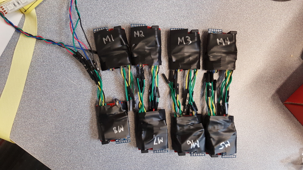
I was not sure what to expect until after observing each accelerometer. Rather than having multiple sketches for each dancer, it was decided to make a condition statement that jumped to a modular function called calibrationADXL335() that contained each calibration just before uploading the code. Here's part of the code written for the MinionAccelerometerV2.1.ino sketch.
language:c
//...
void calibrationADXL335() {
  //function to calibrate ADXL335 accelerometers due to manufacturing tolerances
  //read the values sent through the Arduino serial monitor to determine the values
  //when calibrating. adjust the values accordingly. the values in the brackets are
  //the min/max values used for the condition statements
  if (calibration_M == 1) {
    xUp = 540;      //xRead > xUp, ...~ [550]-580 at REST
    xDown = 488;    //xRead < xDown, it's ~437-[488] at REST
    yUp = 544;      //yRead > yUp, it's ~[544]-580 at REST
    yDown = 480;    //yRead < yDown, it's ~445-[480] at REST
    zUp = 608;      //zRead > zUp, it's ~[608]-642 at REST
    zDown = 435;    //zRead < zDown, it's ~414-[435] at REST
  }
  else  if (calibration_M == 2) {
    xUp = 570;      //xRead > xUp, ...~ [570]-607 at REST
    xDown = 436;    //xRead < xDown, it's ~405-[436] at REST
    yUp = 610;      //yRead > yUp, it's ~[610]-610 at REST
    yDown = 430;    //yRead < yDown, it's ~407-[430] at REST
    zUp = 613;      //zRead > zUp, it's ~[592]-619 at REST
    zDown = 440;    //zRead < zDown, it's ~410-[440] at REST
  }
  else if (calibration_M == 3) {
    xUp = 590;      //xRead > xUp, ...~ [590]-607 at REST
    xDown = 436;    //xRead < xDown, it's ~404-[436] at REST
    yUp = 601;      //yRead > yUp, it's ~[601]-610 at REST
    yDown = 419;    //yRead < yDown, it's ~405-[418] at REST
    zUp = 592;      //zRead > zUp, it's ~[592]-619 at REST
    zDown = 430;    //zRead < zDown, it's ~410-[430] at REST
  }
  else if (calibration_M == 4) {
    xUp = 585;      //xRead > xUp, ...~ [585]-604 at REST
    xDown = 424;    //xRead < xDown, it's ~407-[424] at REST
    yUp = 598;      //yRead > yUp, it's ~[598]-607 at REST
    yDown = 420;    //yRead < yDown, it's ~405-[420] at REST
    zUp = 615;      //zRead > zUp, it's ~[615]-622 at REST
    zDown = 441;    //zRead < zDown, it's ~421-[441] at REST
  }

  else if (calibration_M == 5) {
    xUp = 590;      //xRead > xUp, ...~ [590]-607 at REST
    xDown = 437;    //xRead < xDown, it's ~408-[437] at REST
    yUp = 598;      //yRead > yUp, it's ~[598]-610 at REST
    yDown = 412;    //yRead < yDown, it's ~407-[412] at REST
    zUp = 600;      //zRead > zUp, it's ~[600]-620 at REST
    zDown = 431;    //zRead < zDown, it's ~421-[431] at REST
  }
  else if (calibration_M == 6) {
    xUp = 580;      //xRead > xUp, ...~ [580]-610 at REST
    xDown = 413;    //xRead < xDown, it's ~404-[413] at REST
    yUp = 601;      //yRead > yUp, it's ~[595]-605 at REST
    yDown = 411;    //yRead < yDown, it's ~405-[411] at REST
    zUp = 607;      //zRead > zUp, it's ~[607]-625 at REST
    zDown = 430;    //zRead < zDown, it's ~418-[430] at REST
  }
  else if (calibration_M == 7) {
    xUp = 585;      //xRead > xUp, ...~ [585]-607 at REST
    xDown = 429;    //xRead < xDown, it's ~407-[429] at REST
    yUp = 603;      //yRead > yUp, it's ~[603]-611 at REST
    yDown = 419;    //yRead < yDown, it's ~407-[420] at REST
    zUp = 605;      //zRead > zUp, it's ~[605]-618 at REST
    zDown = 434;    //zRead < zDown, it's ~411-[434] at REST
  }
  else if (calibration_M == 8) {
    xUp = 585;      //xRead > xUp, ...~ [585]-607 at REST
    xDown = 436;    //xRead < xDown, it's ~405-[436] at REST
    yUp = 593;      //yRead > yUp, it's ~[593]-615 at REST
    yDown = 420;    //yRead < yDown, it's ~407-[420] at REST
    zUp = 595;      //zRead > zUp, it's ~[595]-614 at REST
    zDown = 440;    //zRead < zDown, it's ~411-[440] at REST
  }
  else {

    xUp = 585;      //xRead > xUp, ...~ [585]-607 at REST
    xDown = 436;    //xRead < xDown, it's ~405-[436] at REST
    yUp = 601;      //yRead > yUp, it's ~[601]-615 at REST
    yDown = 419;    //yRead < yDown, it's ~404-[419] at REST
    zUp = 616;      //zRead > zUp, it's ~[616]-642 at REST
    zDown = 440;    //zRead < zDown, it's ~410-[440] at REST
  }

  //
  /*
   * //calibration with tech support ADXL335.
    //default calibration_M = 0
    //default calibration for quick test of the adapter board
    xUp = 605;    //xRead > xUp, it's~[600]-604 at REST
    xDown = 411;  //xRead < xDown, it's ~399-[411] at REST
    yUp = 607;    //yRead > yUp, it's ~[607]-612 at REST
    yDown = 409;  //yRead < yDown, it's ~395-[409] at REST
    zUp = 610;    //zRead > zUp, it's ~[610]-618 at REST
    zDown = 425;  //zRead < zDown, it's ~ 410-[425] at REST
    */

}
It was interesting to see that most of the values were close to the first calibration. However, there were a few values that deviated slightly and needed to be adjusted with respect to the accelerometer. When testing the controller during a rehearsal, I noticed that the accelerometer was not positioned perfectly on each dancer. Depending on how tightly the harness was tied, the accelerometer was sometimes loose and not moving perfectly with the dancer. I also noticed that the dancer was not moving perfectly onto their sides as planned. The moves that I imagined to be on their side were actually more at a 45° angle with respect to where the sensor was attached. Certain patterns started triggering as if the dancer was on the left side, stomach, or right side.
With all these conditions in mind, I had to add some padding instead of using the exact maximum/minimum values to trigger the LEDs as expected. I also had to be aware of how tightly the harness was secured for each dancer. Whew, that was exhausting.
Stress Testing in the Field
Benchtop Tests
I tested the harnesses with the new motion controller using a benchtop power supply again for about 60 minutes. At 9V with the motion controller and 78x LEDs, the circuit pulled about ~452mA. At 9V with the motion controller and 90x LEDs (one of my students was a bit taller than the others), it pulled about ~485mA.
Studio Tests
I then tried it out at a studio with choreography using 9V batteries. As noted earlier, I had to add some padding and be aware of how tightly the harness was secured for each dancer so that the LEDs would trigger as expected. Here's a quick demo of it in action.
Dress Rehearsal
After testing and adjusting the code several times, everything went as planned during their dress rehearsal!

 |
 |
Show Time!
With fresh batteries, everything went as planned during the show! I also had some extra batteries, multimeter, tape, and scissors in case I needed to do some last minute troubleshooting.

While I am not able to share the performance with the music, here's some footage of the controller in action backstage! Just ignore my obnoxious voice screaming with excitement behind the camera.
Making It Better
There’s always room for improvement. I was only able to include the option for sensor control from the last time due to time constraints. I would probably explore additional upgrades and improvements on top of the initial list.
- Once Sided Circuit -- It was difficult working with the circuit on two sides of the prototyping board. While it was condensed, reworking parts of the board and wiring the circuit was tedious.
- Printed Circuit Board -- Stripping and soldering wires seemed pretty tedious. Designing and printing circuit boards would be faster if I decide to continue building the motion controller.
- Calibration Methods -- The 6-point calibration process seemed tedious. While it was interesting to view the data and differences between accelerometers, using a different calibration method and automating the process would have been better.
- Combining the Accelerometer with a Gyro -- While the accelerometer is good at determining the object's orientation when static, the reading was a bit noisy when the dancer was moving. I'd probably add a gyro to measure rotation to work with the accelerometer. Using both sensors combined make a inertial measurement unit (IMU) and should interpret the data better.
- Using Different Sensors -- Instead of using an accelerometer as the sensor, it would be neat to try a sound detector to trigger on beat.
For Mark IV and Mark V, I was able to explore some the following options.
- Expanding to the Legs and Arms -- Only the body was lit up. However, the arms and legs could use some lights. It would be cool to extend the LEDs on the arms and legs. This was actually easier to do in Mark IV using EL Wire.
- Wireless Control -- Using some XBees, it would be cool to wirelessly toggle between users or sensor control. This was explored in the Mark IV build.
- Combining EL with LEDs -- It was not until mark Mark V that I was able to add this feature.
Resources & Going Further
For more information, check out the resources below.
- GitHub Project Repo
- Datasheet
- Other Methods of Calibration
- Chionotech: Accelerometer Calibration III: Improving Accuracy With Least-Squares and the Gauss-Newton Method [with the ADXL335]
- SparkFun: ADXL345 Hookup Guide - Calibration - While this is for a digital accelerometer, try checking out the code and process for calibrating an accelerometer.
Need some inspiration for your next e-textiles project? Check out some of these related tutorials:
Hackers in Residence - Sound and Motion Reactivity for Wearables
EL Wire Light-Up Dog Harness
Das Blinken Top Hat
Sound Reactive EL Wire Costume
LilyPad Safety Scarf
EL Wire Hoodie
Qwiic Flex Glove Controller Hookup Guide
Or check out these blog posts for ideas.