Flex Sensor Hookup Guide
 jimblom,
  bboyho
 Introduction
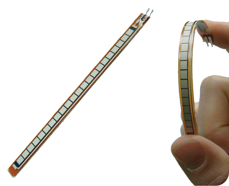
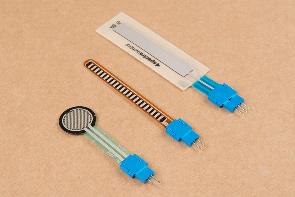
This flex sensor is a variable resistor like no other. The resistance of the flex sensor increases as the body of the component bends. Sensors like these were used in the Nintendo Power Glove. They can also be used as door sensors, robot whisker sensors, or a primary component in creating sentient stuffed animals.
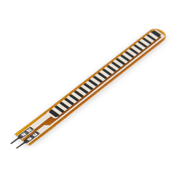
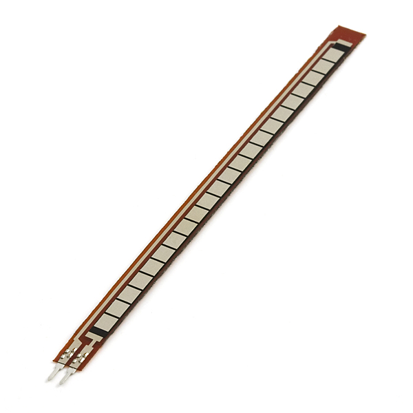
Flex sensors are available in two sizes: one 2.2" (5.588cm) long and another coming in at 4.5" (11.43cm) long.
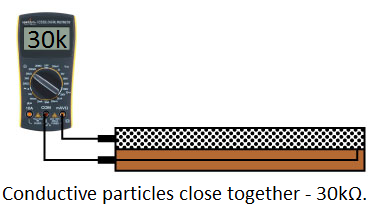
Left flat, these sensors will look like a 30kΩ resistor. As it bends, the resistance between the two terminals will increase to as much as 70kΩ at a 90° angle.
By combining the flex sensor with a static resistor to create a voltage divider, you can produce a variable voltage that can be read by a microcontroller's analog-to-digital converter.
Suggested Materials
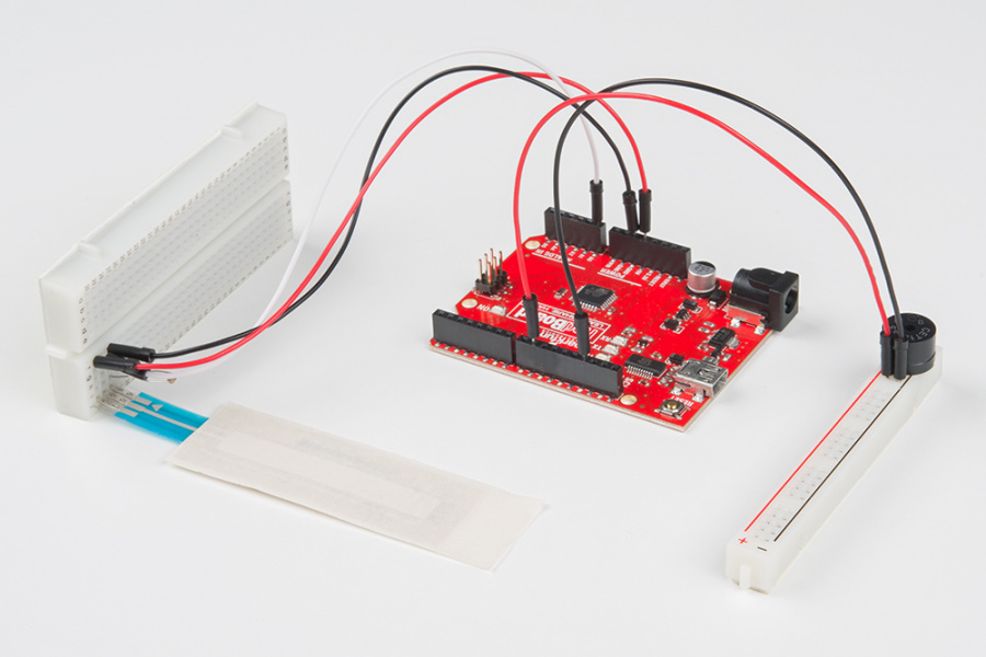
This tutorial serves as a quick primer on flex sensor's, and demonstrates how to hook them up and use them. Aside from the sensor, the following materials are recommended:
Arduino Uno -- We'll be using the Arduino's analog-to-digital converter to read in the variable resistance of the sensor. Any Arduino-compatible development platform -- be it a RedBoard, Pro or Pro Mini -- can substitute.
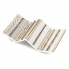
Resistor Kit -- To turn the flex sensor's variable resistance into a readable voltage, we'll combine it with a static resistor to create a voltage divider. This resistor kit is handy for some trial-and-error testing to hone in on the most sensitive circuit possible.
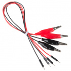
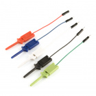
Breadboard and Jumper Wires -- The flex sensor's terminals are breadboard-compatible. We'll stick that and the resistor, then use the jumper wires to connect from breadboard to Arduino.


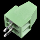
Force Sensitive Resistor Adapter -- While the FSR terminals are breadboard-compatible, we've found that it may be loose in the breadboard. For those looking for a way to make a more secure connection without soldering, try looking at the associated Amphenol pin adapters. You will need a pair of needle nose pliers to clamp the the adapter down.
Suggested Reading
Analog components, like these flex sensor's, are a great sensor-reading entry-point for beginners, but there are a few electronics concepts you should be familiar with. If any of these tutorial titles sound foreign to you, consider skimming through that content first.
Analog to Digital Conversion
Voltage Dividers
What is an Arduino?
Analog vs. Digital
Flex Sensor Overview
Before we get to circuit-building and Arduino-programming, here's a quick rundown of the flex sensor's important electrical characteristics.
How it Works
One side of the sensor is printed with a polymer ink that has conductive particles embedded in it. When the sensor is straight, the particles give the ink a resistance of about 30k Ohms. When the sensor is bent away from the ink, the conductive particles move further apart, increasing this resistance (to about 50k-70K Ohms when the sensor is bent to 90°, as in the diagram below).
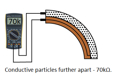
When the sensor straightens out again, the resistance returns to the original value. By measuring the resistance, you can determine how much the sensor is being bent.
The flex sensor is designed to be flexed in just one direction – away from the ink – as demonstrated in the image below.
Flex sensor bend direction (from SpectraSymbol Datasheet).
Bending the sensor in the other direction will not produce any reliable data, and may damage the sensor. Also take care not to bend the sensor close to the base, as they have a tendency to kink and fail.
Hardware Assembly
The sensors have solder tabs that are stapled through a flexible substrate to make contact with the semi-conductive material. Depending on your project application and skill set, there are a few methods of connecting to the sensor. Some assembly may be required to connect to the pins reliably.
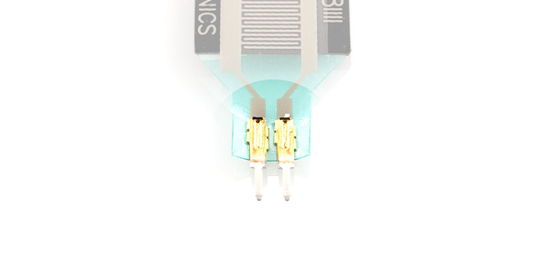
Breadboard Compatible Tabs
For prototyping and testing, these solder tabs can be inserted into a breadboard or female jumper wires. Here are two examples with the flex and soft potentiometer sensors.
 |
 |
| Flex Sensor Inserted Vertically on Breadboard with Space to Bend | SoftPot Inserted Vertically on Breadboard Flush Against the Table |
Soldering to Tabs
When integrating it into a long term project and installation, there is an option to solder wires or a PCB directly to the solder tabs. However, excessive heat can melt the material and damage the sensor due to the limitations in the flexible substrate and the semi-conductive material. Below is an example of the flex sensor soldered to a PCB from our production assembly technicians.
While you can solder to the flex sensor's solder tabs, we only recommended for advanced users that have experience with soldering. For those soldering to the flex sensor, you would need to solder at a lower temperature and ensure that the soldering iron is not heating the tab for no more than 1 second. Any longer and you can damage the material and semi-conductive material. The force sensitive resistor in particular is more susceptible to damage compared to the flex sensors and SoftPot.
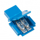
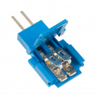
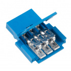
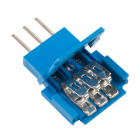
Amphenol CFI Clincher Connector
As an alternative, users can use the Amphenol FCI Clincher connector to make a reliable connection to the sensor and provide a small amount of strain relief on the crimped connector. This is recommended for those that have not soldered before and are using the sensors in an long term projects beyond the breadboard or in a classroom setting. The connector was designed to crimp pins on flexible printed circuits as an alternative to applying heat to heat sensitive components such as the semi-conductive material or conductive ink.
Crimping the Clincher Connector
We'll be using the male Clincher connector to crimp down on the flex sensor. However, the instructions listed below can be applied to any two or three pin flexible sensor as well.
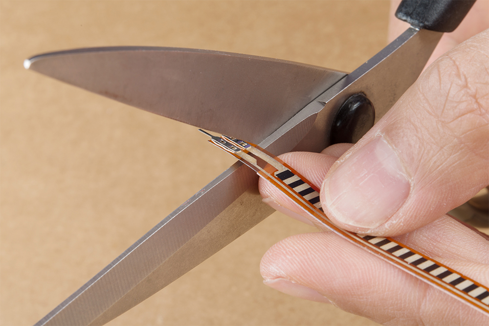
To connect, you will need to cut off the solder tabs on the sensor. Make sure to cut as close to the solder tabs as possible. You can have issues connecting to the semi-conductive material if you cut off too much of the sensor. The length of the semi-conductive pads on the SoftPot is smaller than the force sensitive resistor and flex sensor.
 |
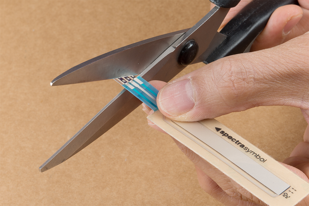 |
| Cutting Solder Tabs Off Flex Sensor | Cutting Solder Tabs Off Slide Pot |
After cutting the staples off, insert the sensor in the respective Clincher connector. Make sure to align the semi-conductive material with the new staples or you may create a short. Depending on the sensor, you may have less semi-conductive material to work with. The SoftPot will have smaller pads to work with after cutting the solder tabs off as shown on the image to the right.
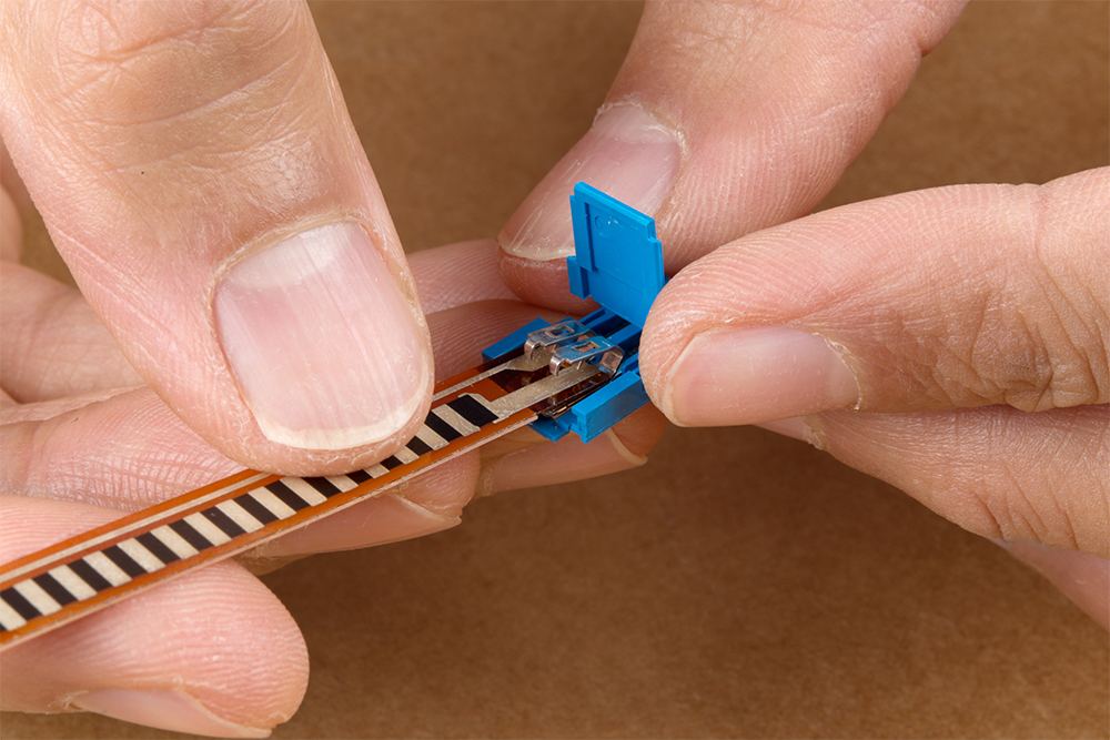 |
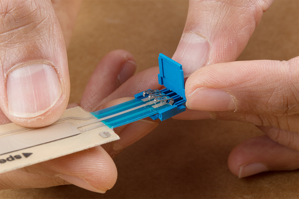 |
| Inserting the Flex Sensor into the 2-Pin Clincher Connector | Inserting the SoftPot Sensor into the 3-Pin Clincher Connector |
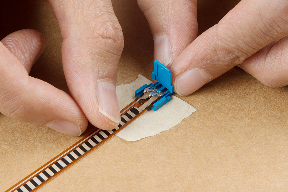
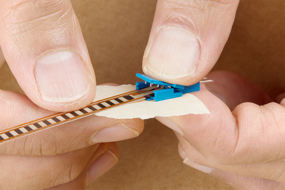
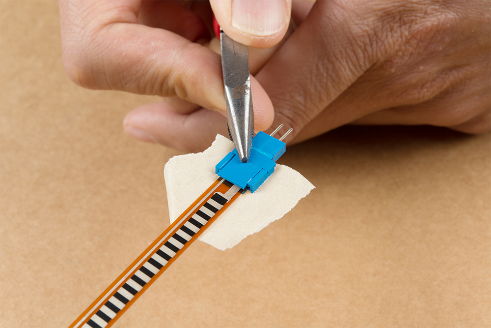
Once you have aligned the sensor, we recommend adding a piece of tape to hold down the sensor with the Clincher connector to prevent the sensor from moving around when clamping the connector down.
We recommend using a flush, slip joint plier to clamp the connector down. As you can see from the image, the force is being applied on the center of the latch and staples instead of along the grooves on the side of the connector. The force sensitive resistor will be easier to clamp down compared to the other flexible substrates on the flex sensor and SoftPot. You will hear a small but satisfying pop when the crimp pins bite through the sensor.
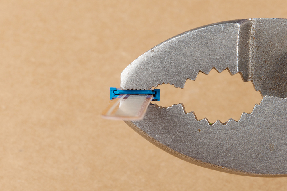
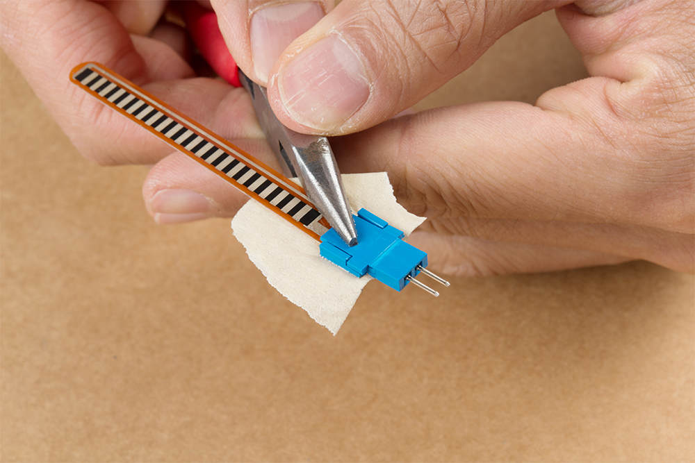
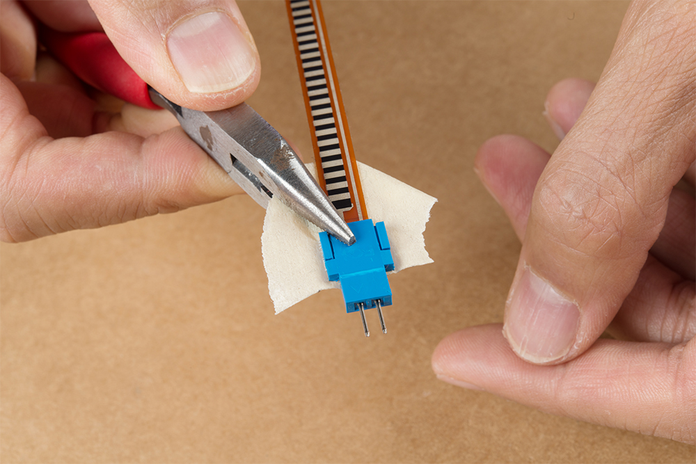
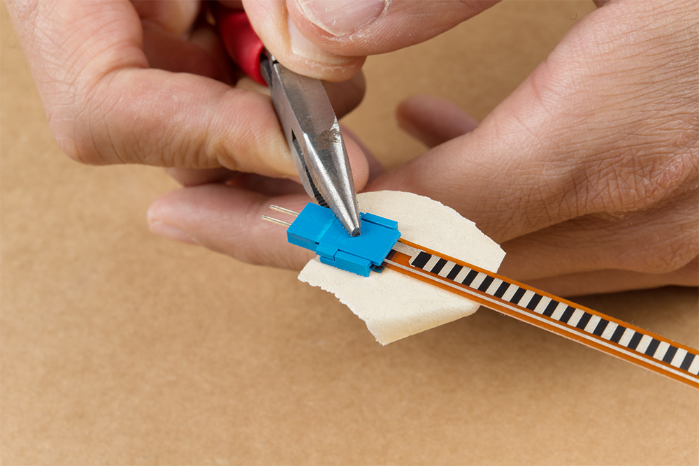
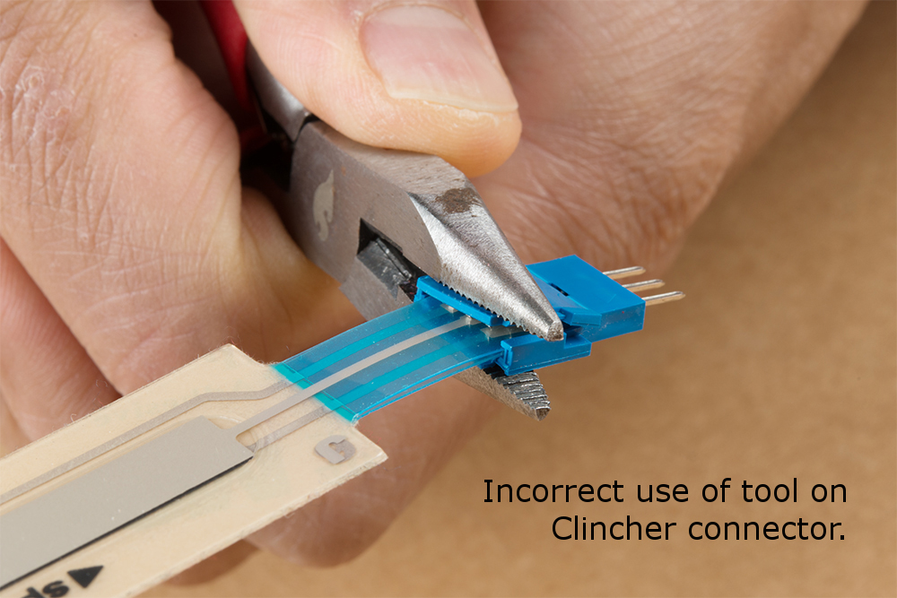
Otherwise, needle nose pliers can be used to clamp the staples to the sensor. Close the tab to hold the crimp pins against the semi-conductive material. Then make sure to carefully apply force on the center from each corner (while avoiding the grooves on the side).
If you apply force incorrectly with needle nose pliers, there is a risk of damaging the plastic housing. The image on the right shows the Clincher connector housing damaged even though the crimp pins are making contact with the SoftPot.
 |
 |
| Pliers applied incorrectly to the Clincher connector. | Clincher connector's housing damaged for the SoftPot. |
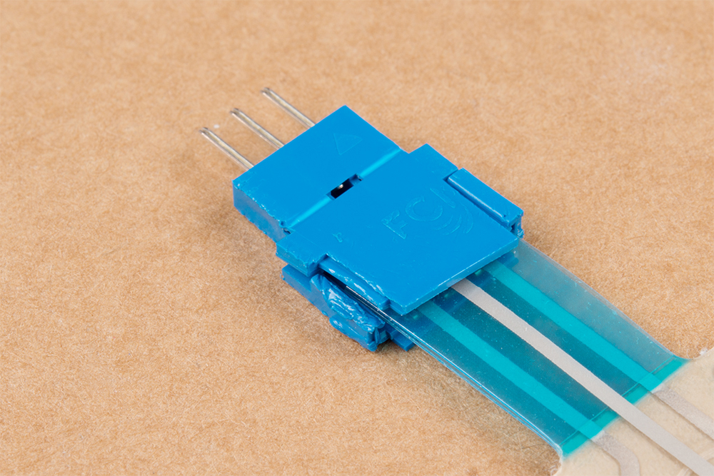
When finished, remove the tape from the back. To test, you can use a multimeter to determine if the sensor has a short or is able change in resistance. You can also connect the sensor to your circuit using jumper wires to check if the sensor is working as expected.
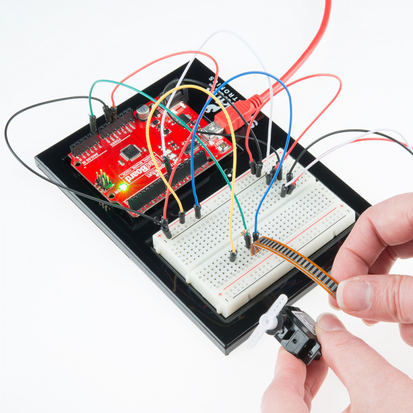
Example Circuit
The simplest way to incorporate this sensor into your project is by using it in a voltage divider. This circuit requires one resistor. Many values from 10KΩ to 100KΩ will work. If you have a resistor kit, you may want to introduce some trial-and-error to hone in on that perfect static resistance.
A value between the minimum and maximum resistance values is usually a good choice. We'll use a 47kΩ resistor in this example. Here's the hookup:
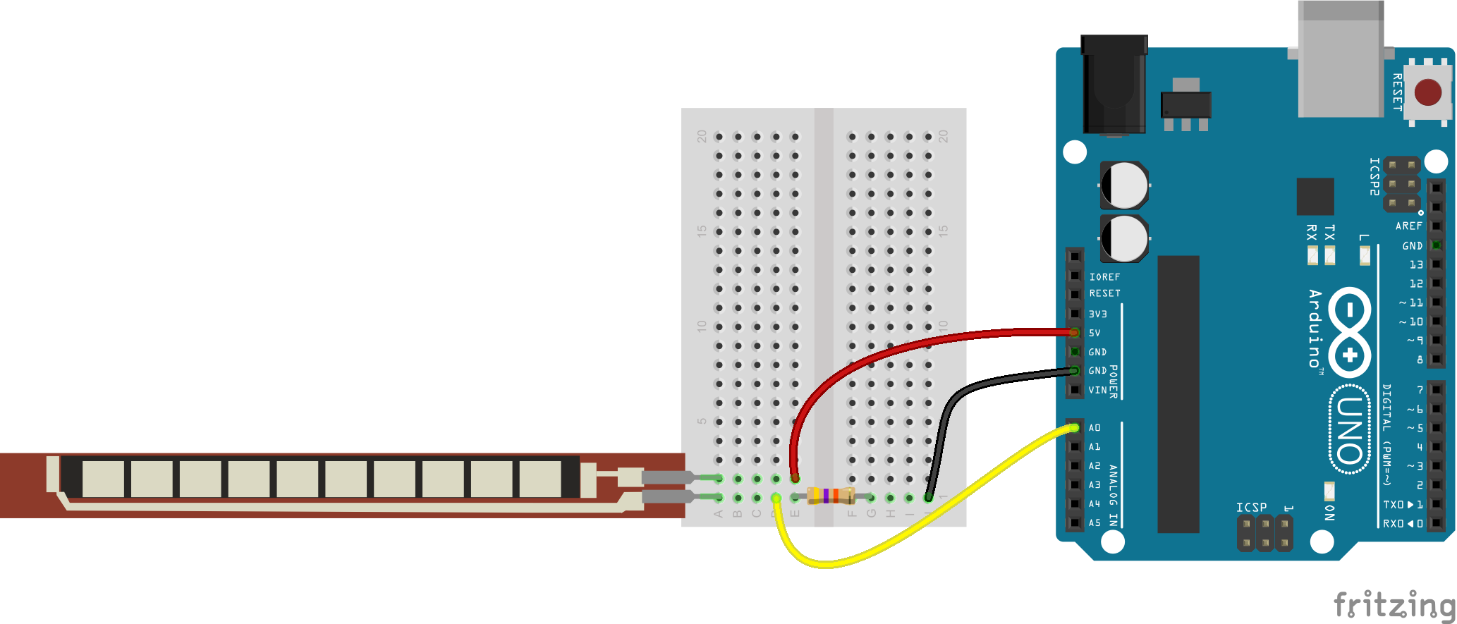
And a schematic:
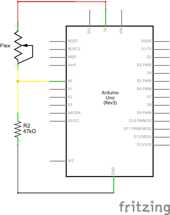
The 47kΩ resistor on the ground side, and the flex sensor on the 5V side, means as the flex sensor's resistance increases (meaning the sensor is bending) the voltage on A0 will decrease.
Example Program
Here is a simple Arduino example based on the circuit above. Copy and paste this into your Arduino IDE, then upload!
Note: This example assumes you are using the latest version of the Arduino IDE on your desktop. If this is your first time using Arduino, please review our tutorial on installing the Arduino IDE.
If you have not previously installed an Arduino library, please check out our installation guide.language:c
/******************************************************************************
Flex_Sensor_Example.ino
Example sketch for SparkFun's flex sensors
(https://www.sparkfun.com/products/10264)
Jim Lindblom @ SparkFun Electronics
April 28, 2016
Create a voltage divider circuit combining a flex sensor with a 47k resistor.
- The resistor should connect from A0 to GND.
- The flex sensor should connect from A0 to 3.3V
As the resistance of the flex sensor increases (meaning it's being bent), the
voltage at A0 should decrease.
Development environment specifics:
Arduino 1.6.7
******************************************************************************/
const int FLEX_PIN = A0; // Pin connected to voltage divider output
// Measure the voltage at 5V and the actual resistance of your
// 47k resistor, and enter them below:
const float VCC = 4.98; // Measured voltage of Ardunio 5V line
const float R_DIV = 47500.0; // Measured resistance of 3.3k resistor
// Upload the code, then try to adjust these values to more
// accurately calculate bend degree.
const float STRAIGHT_RESISTANCE = 37300.0; // resistance when straight
const float BEND_RESISTANCE = 90000.0; // resistance at 90 deg
void setup()
{
Serial.begin(9600);
pinMode(FLEX_PIN, INPUT);
}
void loop()
{
// Read the ADC, and calculate voltage and resistance from it
int flexADC = analogRead(FLEX_PIN);
float flexV = flexADC * VCC / 1023.0;
float flexR = R_DIV * (VCC / flexV - 1.0);
Serial.println("Resistance: " + String(flexR) + " ohms");
// Use the calculated resistance to estimate the sensor's
// bend angle:
float angle = map(flexR, STRAIGHT_RESISTANCE, BEND_RESISTANCE,
0, 90.0);
Serial.println("Bend: " + String(angle) + " degrees");
Serial.println();
delay(500);
}
After uploading, open your serial monitor, and set the baud rate to 9600 bps.
If you bend the flex sensor, you should see resistance and estimated angle calculations change:
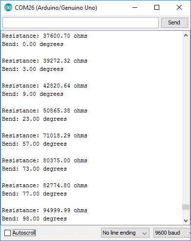
If the value's don't seem correct, make sure the constants VCC and, more importantly, R_DIV are accurate. If you used something other than a 47kΩ resistor, enter that value in for R_DIV.
Through trial-and-error, try to hone in on more accurate values for STRAIGHT_RESISTANCE and BEND_RESISTANCE -- your flex sensor's resistance when it's straight and bent at 90°.
Resources and Going Further
Looking for more flex sensor related documentation? Here are a few sources you may want to consult:
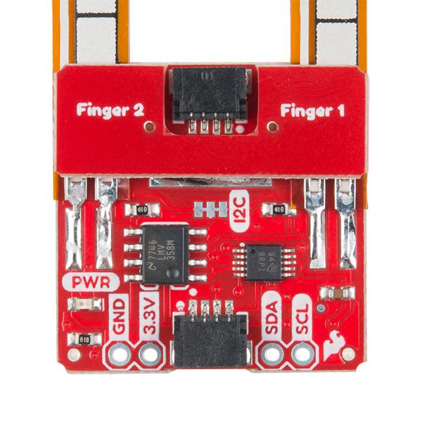
Looking to add the flex sensor to an e-textiles/wearable project? Try using the Qwiic flex glove controller that includes the 4.5" flex sensor.
Qwiic Flex Glove Controller Hookup Guide
Need some project inspiration? Want to check out some similar analog sensors? Check out some of these related tutorials: