Using the Serial 7-Segment Display
 jimblom
Hardware Overview
This page covers the hardware end of the Serial 7-Segment Display (let's shorten that to S7S from here on). Everything from the pin-out, to powering the display is covered here.
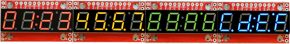
To begin, we should mention, the display comes in an assortment of color options: red, green, blue, yellow, and white.
The Pin-Out
The S7S has a lot of pins broken out in just about every-which direction. Relax! You'll actually only need to connect to about 3-5 of those pins. Most of the pins can be broken down into categories based on the interface for which they're used. This image should do most of the explaining:
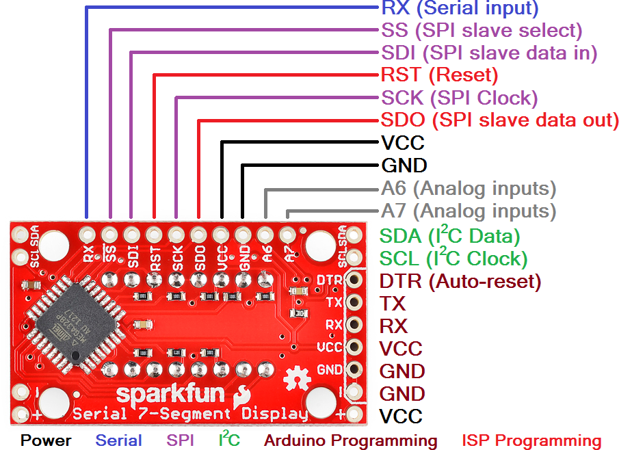
It'll be your choice to decide which of the three serial interfaces you'd like to use to connect to the display. Using a basic serial input, you'll only need to connect to the RX pin. I2C requires two pins, and SPI requires three.
Regardless of which interface you choose to send data, there are two pins to which you must connect: the power pins! VCC and GND.
Powering the Serial 7-Segment Display
To get a S7S up and running, you'll first need to figure out how to power the thing. The S7S can be powered from a variety of voltage supplies. It can operate at anywhere from 3.0V to 5.5V. Keep in mind that the supply voltage will affect how bright the display is -- higher voltages increasing the maximum brightness.
The display's supply voltage is unregulated. So don't give it any crazy-high voltages, anything over 6.0V will harm the display. Be nice to your S7S!
If you're using an Arduino, you could power the S7S off either the 5V or 3.3V headers. Don't forget to connect ground (GND) as well.
Serial Interfaces
The "Serial" in the Serial 7-Segment Displays is something of a generalization. Apt...but this display actually offers three different serial methods of interfacing: Serial UART, SPI and I2C. Each of these interfaces offer their own benefits and disadvantages. A big difference between each of the communication protocols is the number of pins each requires. They also each add their own level of complexity on the firmware end (though, with Arduino, libraries really simplify the task).
UART Serial
UART serial, or TTL serial, this may be the most basic serial communication method on the S7S. If you've played around with Arduino, you've probably used the hardware UART to relay information back to your computer via the Serial Monitor. Or set up a software serial port using the SoftwareSerial library. This form of serial communication is asynchronous, meaning the data is transmitted without any help from a parallel clock signal. This makes our job easier and harder. Easier in that we only need one wire (RX) to communicate with the display. Harder in that extra attention needs to be paid to making sure timing between bits is exact.
The S7S supports a range of very common baud rates, and defaults to everyone's favorite - 9600. The baud rate can be adjusted, if you please, but the display will only allow for 8 data-bits, no parity, and 1 stop bit (8N1).
Serial Peripheral Interface (SPI)
SPI is a synchronous serial communication method. It's kind of like taking the UART method above and adding a clock signal. This way we don't have to worry about what speed we send data (as long as it's not too fast), but we do require the use of two more pins.
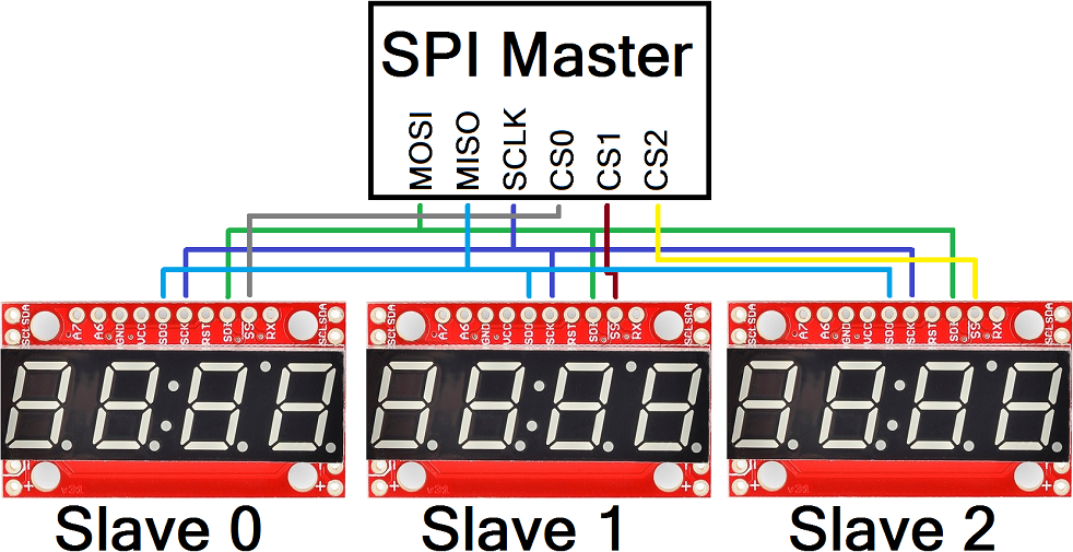
SPI requires three wires for communication: data (SDI, that's "Serial Data In"), clock (SCK, "Serial Clock") and slave-select (SS, with a bar over it meaning it's active low), which is also known as chip select (CS). A couple caveat's on this serial method: the maximum clock speed for the S7S is 250kHz. And, data is clocked in on the rising edge of the clock (when it goes from 0V to 5V). It is also worth noting that the SPI connections on the master device, the Arduino in this case, are typically labeled MISO (Master In Slave Out) and MOSI (Master Out, Slave In). The MOSI line connects to SDI on the S7S, whereas the MISO line connects to the SDO line.
Thanks to the slave-select pin, we can connect multiple SPI devices on a single bus. You could even connect multiple S7S's on the same bus, provided each had its own dedicated select pin.
Inter-Integrated Circuit (I2C)
I2C exists somewhere between SPI and UART serial. This serial method requires only two pins -- SDA (serial data) and SCL (serial clock). Instead of using a chip select pin, like SPI, I2C devices are given unique 7-bit addresses. The I2C address of the S7S is configurable, but defaults to 0x71.
Data on an I2C bus goes both ways, so special acknowledge signals are required to implement a form of handshaking. What I2C lacks in a CS wire, it more than makes up for in complexity of the data signal. Happily though, there are many I2C libraries -- the Wire library for example on Arduino, which makes I2C data transfer simple.
Like SPI, I2C gives you the advantage of being able to tie multiple devices to the same bus. If you need to talk to four segments, program them with unique addresses and link away!
