Using the Serial 7-Segment Display
 jimblom
Firmware Overview
All of the firmware found in this tutorial can be found on the S7S GitHub repo.
Before really delving into the examples, we should discuss what types of data should be sent to the display. As mentioned in the hardware section, the display provides for three serial modes of communication. In each serial mode, data is sent to the display one byte at-a-time. The byte (as bytes go) can be any value from 0 to 255. Data sent to the display will fall into one of three categories:
- displayable data
- command bytes
- command data bytes.
Displayable Data
Displayable data is just that: data sent to the S7S with the intent of actually being displayed. Displayable data bytes include any value from 0-15, and a select few ASCII values.
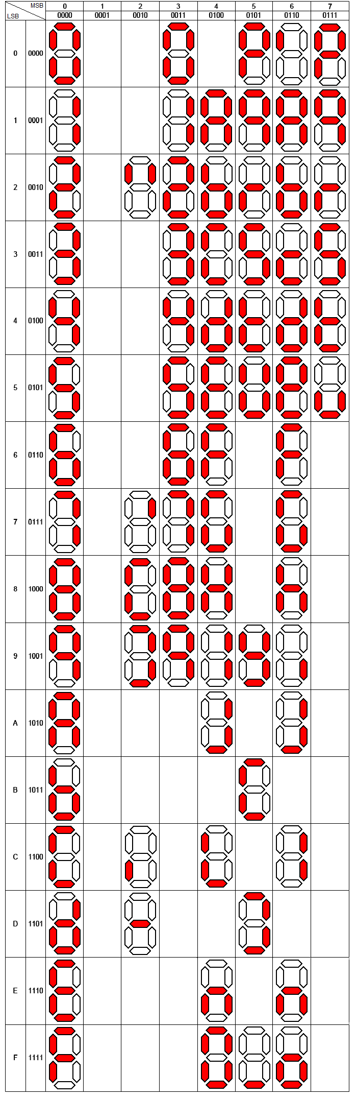
Bytes of value 0-15 will display their hex equivalent (0-9, A-F) on the display. ASCII values (for only the characters that can actually be displayed) will generate an equivalent LED pattern. Not all characters are displayable (the display does what it can with its limited resolution). Here's a table of byte values and the character's displayed:
For example, to display 12Ab you could send a variety of 4-byte patterns:
- The actual byte values 1, 2, 10, and 11:
[0x01] [0x02] [0x0A] [0x0B] - ASCII values for '1', '2', 'a', and 'b':
[0x31] [0x32] [0x41] [0x42] - Or any combination of binary and ASCII values could be used:
[0x01] [0x32] [0x41] [0x0B], etc.
Cursor
Another controlling factor in displaying data is the cursor, which decides where the next piece of received display data will be displayed. You can’t see it, but it’s there. When the S7S starts up, it'll set the cursor to the left-most digit. Every displayable piece of data moves the cursor right one digit, until it wraps around from the fourth digit to the first. The above example assumes the cursor is set at the left-most digit. If not, the display might show 2Ab1, Ab12, or b12A.
Special Commands
Special commands exist to perform non-displayable actions on the display. Actions like clearing the display, setting the cursor, and turning the decimal points on/off are triggered using special commands. In some cases special commands should be followed by a command data byte.
For a complete reference of the available commands, check out the Special Commands section of the datasheet. Let's cover some of the more useful commands: clear display and cursor control.
Clear Display
The clear display command is a single byte of value 0x76. When this value is received by the display two actions are performed: (1) everything on the display is turned off (segments and decimal points), and (2) the cursor is reset to the left-most digit. This command is useful in the example above, if you want to guarantee that the cursor is at the left-most of the display when display data begins coming in.
Cursor Control
The cursor control command is a good example of a command byte that must be followed by a data byte. The cursor command is 0x79, but immediately trailing that should be another byte representing which position you want the cursor to take (e.g. 0 for left-most, 3 for right-most). For example, to set the cursor to the third digit from the left, send 0x79 followed by 0x02.
Here's a quick table of the commands, their command-byte value, and any data-byte they may require:
| Special Command | Command byte | Data byte range | Data byte description |
| Clear display | 0x76 | None | |
| Decimal control | 0x77 | 0-63 | 1-bit per decimal |
| Cursor control | 0x79 | 0-3 | 0=left-most, 3=right-most |
| Brightness control | 0x7A | 0-255 | 0=dimmest, 255=brightest |
| Digit 1 control | 0x7B | 0-127 | 1-bit per segment |
| Digit 2 control | 0x7C | 0-127 | 1-bit per segment |
| Digit 3 control | 0x7D | 0-127 | 1-bit per segment |
| Digit 4 control | 0x7E | 0-127 | 1-bit per segment |
| Baud rate config | 0x7F | 0-11 | See baud rate command in datasheet |
| I2C Address config | 0x80 | 1-126 | New I2C address |
| Factory reset | 0x81 | None |
Enough conceptual stuff. Let's get to some examples!