Using the Serial 7-Segment Display
 jimblom
Introduction
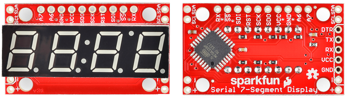
The Serial 7-Segment Display is an easy-to-use 4-digit display that is controlled using a serial interface. Instead of using up a dozen-or-so of your microcontroller's pins to control the LEDs, all you need is one. Using either a serial, I2C, or SPI interface, you can control all digits, decimal points, the colon, and the apostrophe.
The goal of this tutorial is to get you familiar with the Serial 7-Segment Display. We'll cover hardware set-up, assembly, and example interface circuits/code. Given the popularity of Arduino, the examples will make use of the ubiquitous development platform/language.
This tutorial also covers the 7-Segment Shield. If you have the 7-Segment Shield, we recommend going to its tab first and beginning your journey there. The board is very easy to use since you can just plug it straight into an Arduino Uno compatible board and you can use the same exact code examples as the Serial 7-Segment Display which are covered in this tutorial.
Required Materials
Aside from the display itself, you'll need an Arduino (or one of its variants) to send the serial data. In the Arduino's stead, you could use an FTDI Basic, or any device capable of sending TTL serial data.
You'll also need some way to connect between the display and Arduino. You could use a combination of male headers and breadboard. Or, you could just go with a few pieces of wire.
Tools
In order to make use of the Serial 7-Segment Display, you'll need to solder to at least a few of its pins. That means you'll need at least a basic soldering iron as well as solder. Check out our how to solder tutorial for help, if this is you first time soldering.
Before You Begin
Before reading about how to hook up the Serial 7-Segment Display, it'll help to be familiar with some of these concepts. Consider reading through these tutorials before continuing on:
- Binary - The data sent to the display comes in "packets" of bytes. In order to control the decimals or individual segments, knowledge of binary will be important.
- How to Solder - To connect to the display, you'll have to solder either wire, headers, or another connector to it.
- Serial Communication - This is the simplest of the three communication standards used to talk to the display.
- I2C Communication - I2C is a two-wire serial interface. An alternative to serial for talking to the display.
- SPI Communication - SPI is a three (or four) wire serial interface. The third serial option for controlling the LED.
- What is an Arduino? - In this example, we'll use an Arduino to control the LED. If you're not sure what that is, definitely check out this tutorial.
Hardware Overview
This page covers the hardware end of the Serial 7-Segment Display (let's shorten that to S7S from here on). Everything from the pin-out, to powering the display is covered here.
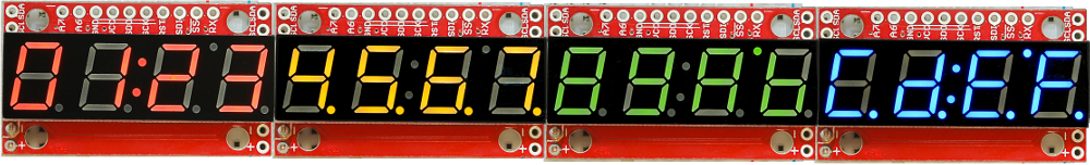
To begin, we should mention, the display comes in an assortment of color options: red, green, blue, yellow, and white.
The Pin-Out
The S7S has a lot of pins broken out in just about every-which direction. Relax! You'll actually only need to connect to about 3-5 of those pins. Most of the pins can be broken down into categories based on the interface for which they're used. This image should do most of the explaining:
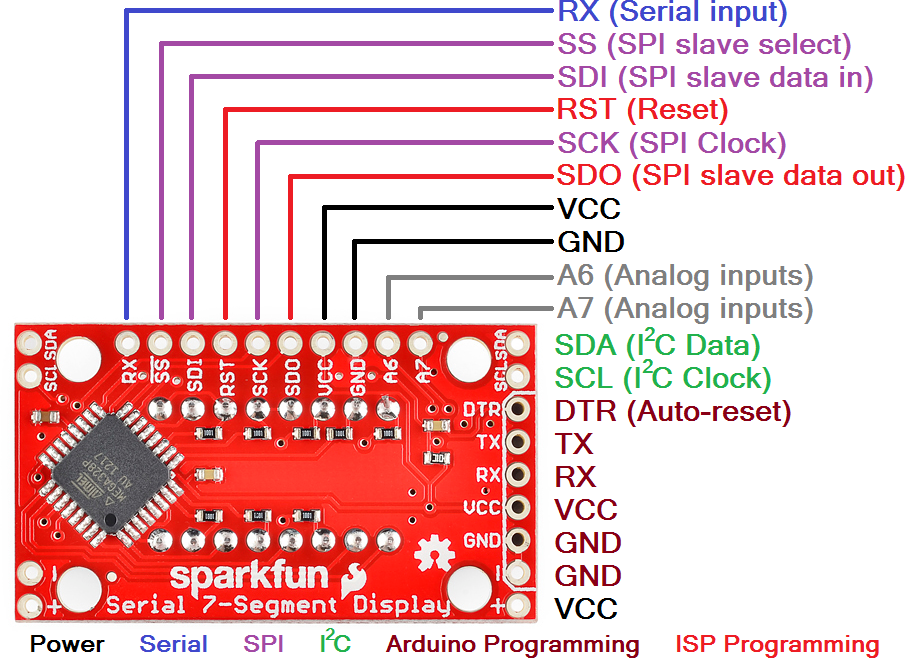
It'll be your choice to decide which of the three serial interfaces you'd like to use to connect to the display. Using a basic serial input, you'll only need to connect to the RX pin. I2C requires two pins, and SPI requires three.
Regardless of which interface you choose to send data, there are two pins to which you must connect: the power pins! VCC and GND.
Powering the Serial 7-Segment Display
To get a S7S up and running, you'll first need to figure out how to power the thing. The S7S can be powered from a variety of voltage supplies. It can operate at anywhere from 3.0V to 5.5V. Keep in mind that the supply voltage will affect how bright the display is -- higher voltages increasing the maximum brightness.
The display's supply voltage is unregulated. So don't give it any crazy-high voltages, anything over 6.0V will harm the display. Be nice to your S7S!
If you're using an Arduino, you could power the S7S off either the 5V or 3.3V headers. Don't forget to connect ground (GND) as well.
Serial Interfaces
The "Serial" in the Serial 7-Segment Displays is something of a generalization. Apt...but this display actually offers three different serial methods of interfacing: Serial UART, SPI and I2C. Each of these interfaces offer their own benefits and disadvantages. A big difference between each of the communication protocols is the number of pins each requires. They also each add their own level of complexity on the firmware end (though, with Arduino, libraries really simplify the task).
UART Serial
UART serial, or TTL serial, this may be the most basic serial communication method on the S7S. If you've played around with Arduino, you've probably used the hardware UART to relay information back to your computer via the Serial Monitor. Or set up a software serial port using the SoftwareSerial library. This form of serial communication is asynchronous, meaning the data is transmitted without any help from a parallel clock signal. This makes our job easier and harder. Easier in that we only need one wire (RX) to communicate with the display. Harder in that extra attention needs to be paid to making sure timing between bits is exact.
The S7S supports a range of very common baud rates, and defaults to everyone's favorite - 9600. The baud rate can be adjusted, if you please, but the display will only allow for 8 data-bits, no parity, and 1 stop bit (8N1).
Serial Peripheral Interface (SPI)
SPI is a synchronous serial communication method. It's kind of like taking the UART method above and adding a clock signal. This way we don't have to worry about what speed we send data (as long as it's not too fast), but we do require the use of two more pins.
SPI requires three wires for communication: data (SDI, that's "Serial Data In"), clock (SCK, "Serial Clock") and slave-select (SS, with a bar over it meaning it's active low), which is also known as chip select (CS). A couple caveat's on this serial method: the maximum clock speed for the S7S is 250kHz. And, data is clocked in on the rising edge of the clock (when it goes from 0V to 5V). It is also worth noting that the SPI connections on the master device, the Arduino in this case, are typically labeled MISO (Master In Slave Out) and MOSI (Master Out, Slave In). The MOSI line connects to SDI on the S7S, whereas the MISO line connects to the SDO line.
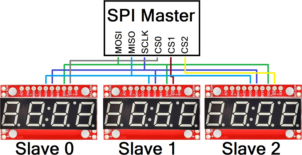
Thanks to the slave-select pin, we can connect multiple SPI devices on a single bus. You could even connect multiple S7S's on the same bus, provided each had its own dedicated select pin.
Inter-Integrated Circuit (I2C)
I2C exists somewhere between SPI and UART serial. This serial method requires only two pins -- SDA (serial data) and SCL (serial clock). Instead of using a chip select pin, like SPI, I2C devices are given unique 7-bit addresses. The I2C address of the S7S is configurable, but defaults to 0x71.
Data on an I2C bus goes both ways, so special acknowledge signals are required to implement a form of handshaking. What I2C lacks in a CS wire, it more than makes up for in complexity of the data signal. Happily though, there are many I2C libraries -- the Wire library for example on Arduino, which makes I2C data transfer simple.
Like SPI, I2C gives you the advantage of being able to tie multiple devices to the same bus. If you need to talk to four segments, program them with unique addresses and link away!

Assembly
To interface other electronics to the display, you'll need to solder to some of the S7S's pins. Before you do any soldering, though, think on how you want to use the display. Do you plan on using one of the serial interfaces in particular? Maybe you only need to solder to the power pins, and the few pins which correspond to your preferred interface. Are you just prototyping with the display? Are you mounting it in an project enclosure? Your assembly method really depends on what your final goals for the display are.
For many use cases, you'll really only need the pins on the top header. When I prototype with these displays, I like to solder some straight male headers in, so I can stick it into a breadboard.
Of course, you could solder stranded or solid-core wires into the pins you need. This is useful if you plan on mounting the display in an enclosure.
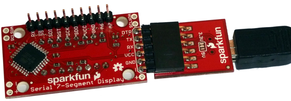
If you intend to ever reprogram the display using an FTDI Basic, you might find it useful to solder some right-angle male headers into the serial programming header. This can be a bit tricky, as the display gets in the way. I solder my right-angler's on the curved side.
Finally, if you'll be mounting the display, any 4-40 screw should be able to find its way through those stand-off holes.
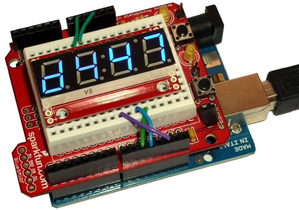
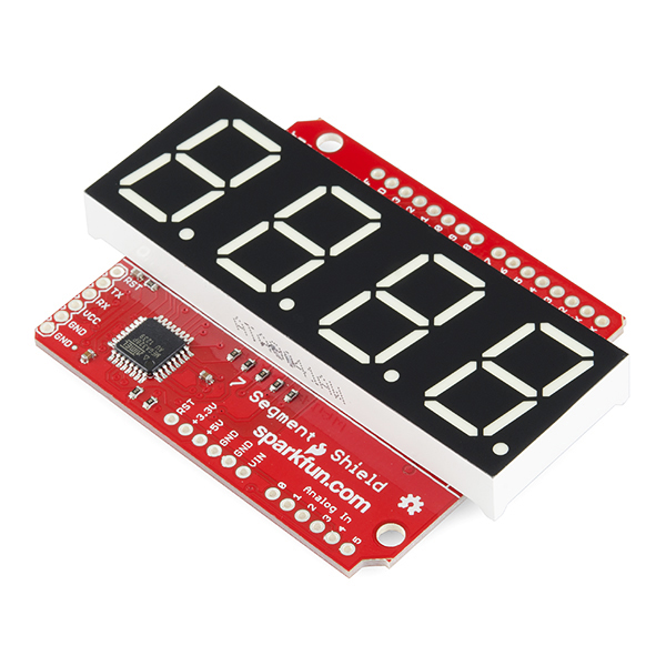
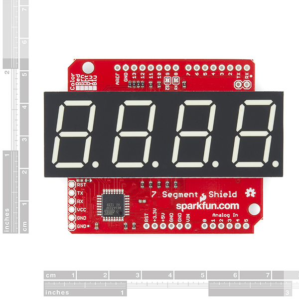
7-Segment Shield
If you're looking for an even simpler form factor of the S7S, take a look at the 7-Segment Shield display. The S7S Display Shield is an Arduino shield designed to run on top of an Arduino Uno or an Arduino Uno compatible board. It runs the same firmware as the OpenSegment and Serial 7-Segment displays and is controlled in the same manner. It is arguably the easiest of the three to get up in running as all you have to do is populate the standard Arduino headers, a 7-segment display of your choice, and then plug the shield into an Arduino Uno compatible board. For more instructions on shield assembly, visit our shield tutorial.
Similarities and Differences
Just like its brother boards, the serial 7-segment shield can be controlled via SPI, I2C, and serial communication. You can choose which communication protocol works best for your specific application leaving the others open to interact with other pieces of hardware. It shares the same command set, and all the same example Arduino sketches work for it as well without needing to change a single line of code.
Since all communication protocols are connected by default, there is the option of disabling both the SPI or Serial communication streams. You only need to disable these if they conflict with other devices you want to communicate with, otherwise you can leave them alone. You can disable SPI by desoldering the Chip Select pin (CS). You can disable Serial by desoldering the shield's receive pin (RX). These jumpers are located in the top center of the picture below.
So what about I2C? Well while I2C can't be disabled in the same manner, it shouldn't conflict with another I2C device on the same bus unless they share the same address. In this case, you can reprogram the shield's firmware with a different I2C address. The shield's I2C address is 0x71 by default.
When comparing the displayable data, both have four 7-segments and four decimal places. However, the 7-segment shield does not have a colon or apostrophe available. Any commands to turn on the colon and apostrophe will not display on the 7-segment shield.
Super Quick Start Guide
- Solder headers to the 7-Segment Shield Display.
- Mate to an Arduino Uno compatible board.
- Choose one of the basic example Arduino sketches and download it from here.
- Upload example sketch to your Arduino.
- If 1-4 went correctly, your display should now be counting upwards.
- Continue reading the Example coding sections of this tutorial to get a better grasp of the code.
If you're ready to take the plunge into creating your own sketches, feel free. If you want a bit more explanation of one of the basic sketches, visit the following coding sections of this tutorial. Simply plug in your shield to an Arduino, and follow along.
Firmware Overview
All of the firmware found in this tutorial can be found on the S7S GitHub repo.
Before really delving into the examples, we should discuss what types of data should be sent to the display. As mentioned in the hardware section, the display provides for three serial modes of communication. In each serial mode, data is sent to the display one byte at-a-time. The byte (as bytes go) can be any value from 0 to 255. Data sent to the display will fall into one of three categories:
- displayable data
- command bytes
- command data bytes.
Displayable Data
Displayable data is just that: data sent to the S7S with the intent of actually being displayed. Displayable data bytes include any value from 0-15, and a select few ASCII values.
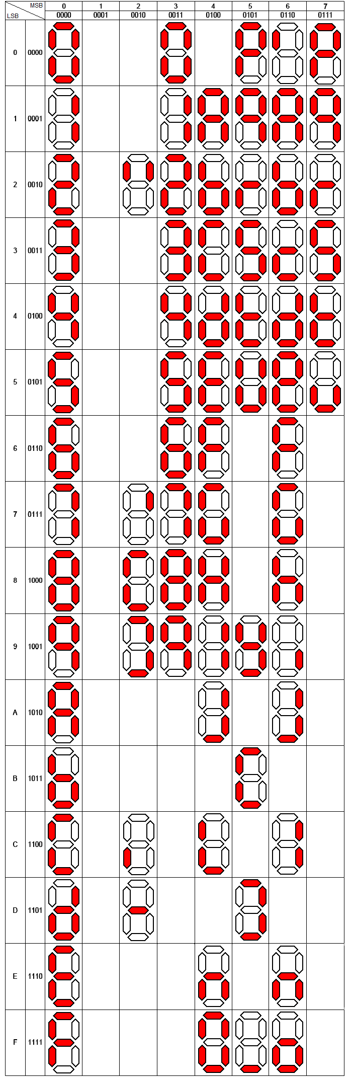
Bytes of value 0-15 will display their hex equivalent (0-9, A-F) on the display. ASCII values (for only the characters that can actually be displayed) will generate an equivalent LED pattern. Not all characters are displayable (the display does what it can with its limited resolution). Here's a table of byte values and the character's displayed:
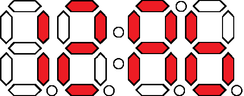
For example, to display 12Ab you could send a variety of 4-byte patterns:
- The actual byte values 1, 2, 10, and 11:
[0x01] [0x02] [0x0A] [0x0B] - ASCII values for '1', '2', 'a', and 'b':
[0x31] [0x32] [0x41] [0x42] - Or any combination of binary and ASCII values could be used:
[0x01] [0x32] [0x41] [0x0B], etc.
Cursor
Another controlling factor in displaying data is the cursor, which decides where the next piece of received display data will be displayed. You can’t see it, but it’s there. When the S7S starts up, it'll set the cursor to the left-most digit. Every displayable piece of data moves the cursor right one digit, until it wraps around from the fourth digit to the first. The above example assumes the cursor is set at the left-most digit. If not, the display might show 2Ab1, Ab12, or b12A.
Special Commands
Special commands exist to perform non-displayable actions on the display. Actions like clearing the display, setting the cursor, and turning the decimal points on/off are triggered using special commands. In some cases special commands should be followed by a command data byte.
For a complete reference of the available commands, check out the Special Commands section of the datasheet. Let's cover some of the more useful commands: clear display and cursor control.
Clear Display
The clear display command is a single byte of value 0x76. When this value is received by the display two actions are performed: (1) everything on the display is turned off (segments and decimal points), and (2) the cursor is reset to the left-most digit. This command is useful in the example above, if you want to guarantee that the cursor is at the left-most of the display when display data begins coming in.
Cursor Control
The cursor control command is a good example of a command byte that must be followed by a data byte. The cursor command is 0x79, but immediately trailing that should be another byte representing which position you want the cursor to take (e.g. 0 for left-most, 3 for right-most). For example, to set the cursor to the third digit from the left, send 0x79 followed by 0x02.
Here's a quick table of the commands, their command-byte value, and any data-byte they may require:
| Special Command | Command byte | Data byte range | Data byte description |
| Clear display | 0x76 | None | |
| Decimal control | 0x77 | 0-63 | 1-bit per decimal |
| Cursor control | 0x79 | 0-3 | 0=left-most, 3=right-most |
| Brightness control | 0x7A | 0-255 | 0=dimmest, 255=brightest |
| Digit 1 control | 0x7B | 0-127 | 1-bit per segment |
| Digit 2 control | 0x7C | 0-127 | 1-bit per segment |
| Digit 3 control | 0x7D | 0-127 | 1-bit per segment |
| Digit 4 control | 0x7E | 0-127 | 1-bit per segment |
| Baud rate config | 0x7F | 0-11 | See baud rate command in datasheet |
| I2C Address config | 0x80 | 1-126 | New I2C address |
| Factory reset | 0x81 | None |
Enough conceptual stuff. Let's get to some examples!
Example 1: Serial UART
Serial is a great communication method if you want to minimize wires. If you're linking the S7S up to an Arduino, I'd really recommend you make use of the Software Serial library (included with Arduino) to communicate with the display, rather than hooking up to the hardware serial pins (D0, D1). This will make sure there's no bus contention, and, more importantly, it makes sure your display doesn't receive any data meant for solely your Arduino.
This example will require three wires between the Arduino and S7S (two power wires, one data). Hook it up like so:
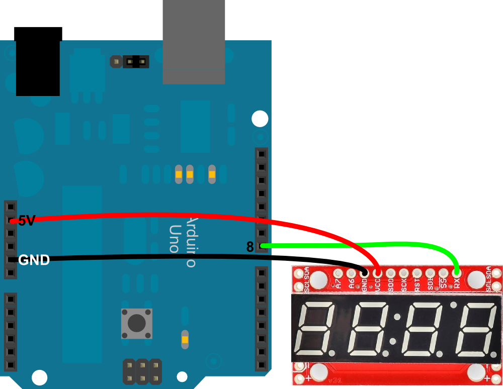
Really, you can use any digital pin to serve as the Arduino's software TX pin. Just make sure you change it in the code. Speaking of the code copy/past this, or you can download it from here:
language:c
/* Serial 7-Segment Display Example Code
    Serial Mode Stopwatch
   by: Jim Lindblom
     SparkFun Electronics
   date: November 27, 2012
   license: This code is public domain.

   This example code shows how you could use software serial
   Arduino library to interface with a Serial 7-Segment Display.

   There are example functions for setting the display's
   brightness, decimals and clearing the display.

   The print function is used with the SoftwareSerial library
   to send display data to the S7S.

   Circuit:
   Arduino -------------- Serial 7-Segment
     5V   --------------------  VCC
     GND  --------------------  GND
      8   --------------------  RX
*/
#include <SoftwareSerial.h>

// These are the Arduino pins required to create a software seiral
//  instance. We'll actually only use the TX pin.
const int softwareTx = 8;
const int softwareRx = 7;

SoftwareSerial s7s(softwareRx, softwareTx);

unsigned int counter = 0;  // This variable will count up to 65k
char tempString[10];  // Will be used with sprintf to create strings

void setup()
{
  // Must begin s7s software serial at the correct baud rate.
  //  The default of the s7s is 9600.
  s7s.begin(9600);

  // Clear the display, and then turn on all segments and decimals
  clearDisplay();  // Clears display, resets cursor
  s7s.print("-HI-");  // Displays -HI- on all digits
  setDecimals(0b111111);  // Turn on all decimals, colon, apos

  // Flash brightness values at the beginning
  setBrightness(0);  // Lowest brightness
  delay(1500);
  setBrightness(127);  // Medium brightness
  delay(1500);
  setBrightness(255);  // High brightness
  delay(1500);

  // Clear the display before jumping into loop
  clearDisplay();
}

void loop()
{
  // Magical sprintf creates a string for us to send to the s7s.
  //  The %4d option creates a 4-digit integer.
  sprintf(tempString, "%4d", counter);

  // This will output the tempString to the S7S
  s7s.print(tempString);
  setDecimals(0b00000100);  // Sets digit 3 decimal on

  counter++;  // Increment the counter
  delay(100);  // This will make the display update at 10Hz.
}

// Send the clear display command (0x76)
//  This will clear the display and reset the cursor
void clearDisplay()
{
  s7s.write(0x76);  // Clear display command
}

// Set the displays brightness. Should receive byte with the value
//  to set the brightness to
//  dimmest------------->brightest
//     0--------127--------255
void setBrightness(byte value)
{
  s7s.write(0x7A);  // Set brightness command byte
  s7s.write(value);  // brightness data byte
}

// Turn on any, none, or all of the decimals.
//  The six lowest bits in the decimals parameter sets a decimal
//  (or colon, or apostrophe) on or off. A 1 indicates on, 0 off.
//  [MSB] (X)(X)(Apos)(Colon)(Digit 4)(Digit 3)(Digit2)(Digit1)
void setDecimals(byte decimals)
{
  s7s.write(0x77);
  s7s.write(decimals);
}
In that code there are example functions for setting the display's brightness, decimals, and clearing the display. Check out the functions and the comments, for more details.
The sketch begins by cycling through a select few brightnesses, so you can see what the display looks at its dimmest and brightest. Following that, it turns into a stopwatch, making use of the s7s.print() function to send data to the display via the software serial library.
Example 2: SPI
SPI is a useful communication method if you have more than one device to hook up on a single bus. It requires more wires than basic serial, but it's more dependable because it's a synchronous interface.
In this example, we'll only use a single display. Realize, though, that you could add more displays (or other SPI devices) to the same SPI bus, each requiring only an additional SS pin per device.
Here's the hardware setup:
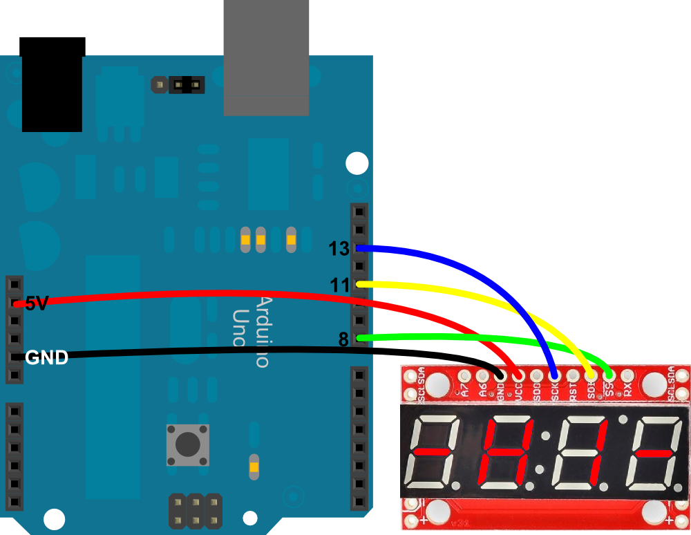
The SDI and SCK pins must remain where they are on the Arduino - those are the hardware SPI pins. The SS pin could be moved to any digital pin, as long as it's changed in the code.
Speaking of code, copy/paste from below, or you can download it in a zip file by clicking here.
language:c
/* Serial 7-Segment Display Example Code
    SPI Mode Stopwatch
   by: Jim Lindblom
     SparkFun Electronics
   date: November 27, 2012
   license: This code is public domain.

   This example code shows how you could use the Arduino SPI
   library to interface with a Serial 7-Segment Display.

   There are example functions for setting the display's
   brightness, decimals and clearing the display.

   The SPI.transfer() function is used to send a byte of the
   SPI wires. Notice that each SPI transfer(s) is prefaced by
   writing the SS pin LOW and closed by writing it HIGH.

   Each of the custom functions handle the ssPin writes as well
   as the SPI.transfer()'s.

   There's a custom function used to send a sequence of bytes
   over SPI - s7sSendStringSPI, which can be used somewhat like
   the serial print statements.

   Circuit:
   Arduino -------------- Serial 7-Segment
     5V   --------------------  VCC
     GND  --------------------  GND
      8   --------------------  SS
     11   --------------------  SDI
     13   --------------------  SCK
*/
#include <SPI.h> // Include the Arduino SPI library

// Define the SS pin
//  This is the only pin we can move around to any available
//  digital pin.
const int ssPin = 8;

unsigned int counter = 0;  // This variable will count up to 65k
char tempString[10];  // Will be used with sprintf to create strings

void setup()
{
  // -------- SPI initialization
  pinMode(ssPin, OUTPUT);  // Set the SS pin as an output
  digitalWrite(ssPin, HIGH);  // Set the SS pin HIGH
  SPI.begin();  // Begin SPI hardware
  SPI.setClockDivider(SPI_CLOCK_DIV64);  // Slow down SPI clock
  // --------

  // Clear the display, and then turn on all segments and decimals
  clearDisplaySPI();  // Clears display, resets cursor

  // Custom function to send four bytes via SPI
  //  The SPI.transfer function only allows sending of a single
  //  byte at a time.
  s7sSendStringSPI("-HI-");
  setDecimalsSPI(0b111111);  // Turn on all decimals, colon, apos

  // Flash brightness values at the beginning
  setBrightnessSPI(0);  // Lowest brightness
  delay(1500);
  setBrightnessSPI(255);  // High brightness
  delay(1500);

  // Clear the display before jumping into loop
  clearDisplaySPI();
}

void loop()
{
  // Magical sprintf creates a string for us to send to the s7s.
  //  The %4d option creates a 4-digit integer.
  sprintf(tempString, "%4d", counter);

  // This will output the tempString to the S7S
  s7sSendStringSPI(tempString);

  // Print the decimal at the proper spot
  if (counter < 10000)
    setDecimalsSPI(0b00000010);  // Sets digit 3 decimal on
  else
    setDecimalsSPI(0b00000100);

  counter++;  // Increment the counter
  delay(10);  // This will make the display update at 100Hz.*/
}

// This custom function works somewhat like a serial.print.
//  You can send it an array of chars (string) and it'll print
//  the first 4 characters in the array.
void s7sSendStringSPI(String toSend)
{
  digitalWrite(ssPin, LOW);
  for (int i=0; i<4; i++)
  {
    SPI.transfer(toSend[i]);
  }
  digitalWrite(ssPin, HIGH);
}

// Send the clear display command (0x76)
//  This will clear the display and reset the cursor
void clearDisplaySPI()
{
  digitalWrite(ssPin, LOW);
  SPI.transfer(0x76);  // Clear display command
  digitalWrite(ssPin, HIGH);
}

// Set the displays brightness. Should receive byte with the value
//  to set the brightness to
//  dimmest------------->brightest
//     0--------127--------255
void setBrightnessSPI(byte value)
{
  digitalWrite(ssPin, LOW);
  SPI.transfer(0x7A);  // Set brightness command byte
  SPI.transfer(value);  // brightness data byte
  digitalWrite(ssPin, HIGH);
}

// Turn on any, none, or all of the decimals.
//  The six lowest bits in the decimals parameter sets a decimal
//  (or colon, or apostrophe) on or off. A 1 indicates on, 0 off.
//  [MSB] (X)(X)(Apos)(Colon)(Digit 4)(Digit 3)(Digit2)(Digit1)
void setDecimalsSPI(byte decimals)
{
  digitalWrite(ssPin, LOW);
  SPI.transfer(0x77);
  SPI.transfer(decimals);
  digitalWrite(ssPin, HIGH);
}
This example works a lot like the serial version. The s7s.print() functions from the previous example are replaced by SPI transfers. Take note that each time an SPI.transfer() occurs, it's blanketed by two digitalWrite()s to the SS pin. The SS pin must go LOW, to let the display know that usable data is incoming. Once SS goes back to HIGH, the display will know that data is no longer being sent to it.
Example 3: I2C
Finally, I2C. I2C is a really powerful communication method, but it's also the most complicated of the three discussed here. Happily, though, Arduino's got a great library (Wire) to handle all of the nasty I2C stuff.
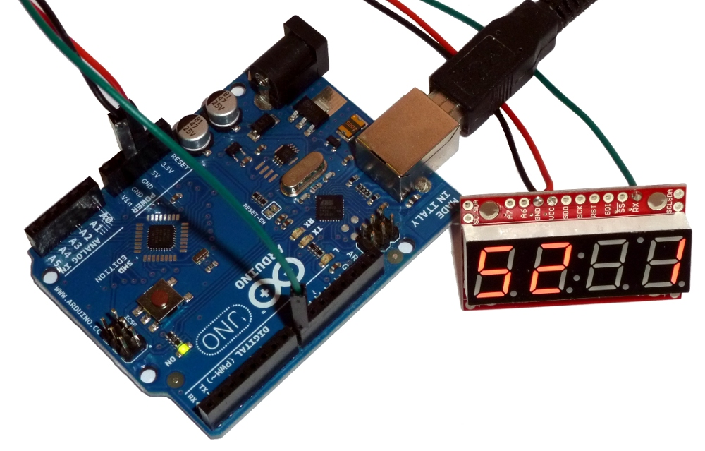
Only two data wires are required for I2C -- a data line (SDA) and a clock line (SCL). Don't forget power! Here's how to hook it up:
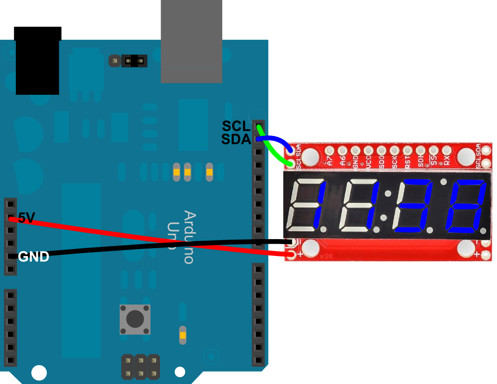
There's not any give in this pin configuration; you'll have to use the hardware I2C pins. Older Arduinos may not have the devoted SDA and SCL pins. They should still be there, on pins A4 and A5 respectively.
You may have noticed I2C pins (as well as power pins) exist on both sides of the S7S. These are useful if you want to link many S7S's together on a single I2C bus. Thanks to I2C's addressing scheme, you could chain a large-ish number of Serial 7-Segment displays using just these two I2C pins. Should be useful if you're making a national debt clock!
Here's some example code, using I2C (download here). The functionality is comparable to the last couple of example sketches:
language:c
/* Serial 7-Segment Display Example Code
    I2C Mode Stopwatch
   by: Jim Lindblom
     SparkFun Electronics
   date: November 27, 2012
   license: This code is public domain.

   This example code shows how you could use the Arduino Wire
   library to interface with a Serial 7-Segment Display.

   There are example functions for setting the display's
   brightness, decimals, clearing the display, and sending a
   series of bytes via I2C.

   Each I2C transfer begins with a Wire.beginTransmission(address)
   where address is the 7-bit address of the device set to
   receive the data. Wire.write() sends a byte of data. I2C
   communication is closed with Wire.endTransmission().

   Circuit:
   Arduino -------------- Serial 7-Segment
     5V   --------------------  VCC
     GND  --------------------  GND
     SDA  --------------------  SDA (A4 on older 'duino's)
     SCL  --------------------  SCL (A5 on older 'duino's)
*/
#include <Wire.h> // Include the Arduino SPI library

// Here we'll define the I2C address of our S7S. By default it
//  should be 0x71. This can be changed, though.
const byte s7sAddress = 0x71;

unsigned int counter = 9900;  // This variable will count up to 65k
char tempString[10];  // Will be used with sprintf to create strings

void setup()
{
  Wire.begin();  // Initialize hardware I2C pins

  // Clear the display, and then turn on all segments and decimals
  clearDisplayI2C();  // Clears display, resets cursor

  // Custom function to send four bytes via I2C
  //  The I2C.write function only allows sending of a single
  //  byte at a time.
  s7sSendStringI2C("-HI-");
  setDecimalsI2C(0b111111);  // Turn on all decimals, colon, apos

  // Flash brightness values at the beginning
  setBrightnessI2C(0);  // Lowest brightness
  delay(1500);
  setBrightnessI2C(255);  // High brightness
  delay(1500);

  // Clear the display before jumping into loop
  clearDisplayI2C();
}

void loop()
{
  // Magical sprintf creates a string for us to send to the s7s.
  //  The %4d option creates a 4-digit integer.
  sprintf(tempString, "%4d", counter);

  // This will output the tempString to the S7S
  s7sSendStringI2C(tempString);

  // Print the decimal at the proper spot
  if (counter < 10000)
    setDecimalsI2C(0b00000100);  // Sets digit 3 decimal on
  else
    setDecimalsI2C(0b00001000);

  counter++;  // Increment the counter
  delay(100);  // This will make the display update at 10Hz.*/
}

// This custom function works somewhat like a serial.print.
//  You can send it an array of chars (string) and it'll print
//  the first 4 characters in the array.
void s7sSendStringI2C(String toSend)
{
  Wire.beginTransmission(s7sAddress);
  for (int i=0; i<4; i++)
  {
    Wire.write(toSend[i]);
  }
  Wire.endTransmission();
}

// Send the clear display command (0x76)
//  This will clear the display and reset the cursor
void clearDisplayI2C()
{
  Wire.beginTransmission(s7sAddress);
  Wire.write(0x76);  // Clear display command
  Wire.endTransmission();
}

// Set the displays brightness. Should receive byte with the value
//  to set the brightness to
//  dimmest------------->brightest
//     0--------127--------255
void setBrightnessI2C(byte value)
{
  Wire.beginTransmission(s7sAddress);
  Wire.write(0x7A);  // Set brightness command byte
  Wire.write(value);  // brightness data byte
  Wire.endTransmission();
}

// Turn on any, none, or all of the decimals.
//  The six lowest bits in the decimals parameter sets a decimal
//  (or colon, or apostrophe) on or off. A 1 indicates on, 0 off.
//  [MSB] (X)(X)(Apos)(Colon)(Digit 4)(Digit 3)(Digit2)(Digit1)
void setDecimalsI2C(byte decimals)
{
  Wire.beginTransmission(s7sAddress);
  Wire.write(0x77);
  Wire.write(decimals);
  Wire.endTransmission();
}
Now SPI.transfer()s from the last example are replaced with Wire.write()s. And instead of toggling a SS pin, we use Wire.beginTransmission(address) and Wire.endTransmission(). Easy enough!
Troubleshooting
Default Firmware v3.1
If you are having issues uploading the most recent default firmware to the smaller (10mm) serial enabled 7-segment display via the Arduino IDE, try using the older version of the firmware in the GitHub v3.1 branch. This is the same firmware that is used in our production department.
Factory Reset
Having issues with the serial UART example, SPI, and/or I2C example code? You could try a factory reset with the microcontroller on the 7-segment serial display by:
If you believe that the smaller (10mm) 7-segment serial display has corrupt firmware, you could also reinstall the Arduino bootloader. You could use an AVR programmer to reflash the ATmega328P on the serial enabled 7-segment display.
| Smaller (10mm) Serial Enabled 7-Segment Display | AVR Programmer | Arduino Uno as ISP |
| SDI | MOSI | D11 |
| RST | RST | D10 |
| SCK | SCK | D13 |
| SDO | MISO | D12 |
| VCC | VCC | 5V |
| GND | GND | GND |
If you are using the latest default firmware from the master branch, make sure that you have the correct “DISPLAY_TYPE” defined in the Serial_7_Segment_Display_Firmware.ino code. This is on line 39 of the GitHub master branch. Just change OPENSEGMENT to any of the other hardware layouts. Otherwise, the display with show "0000" as explained in the Arduino Forum: Arduino Uno - 7 Segment Shield Problem .
Microcontroller Sending Commands Too Fast to Serial 7-Segment Display
If you have issues using the serial enabled 7-segment display where the LEDs flicker and display random numbers, it could be the way that you wrote your code. There was one case that tech support encountered where this happened after using a sequence of commands to clearing the screen, setting the mode, setting the brightness, and adjusting the cursor.
Testing with a 5V RedBoard, the major issues that seemed to be fixed was removing the clearDisplay() function and adding a delay between setting the brightness and your cursor position. The flickering may be due to clearing the screen and writing back on the screen in your main function. By avoiding the clear screen function every time my main function looped back, the serial enabled 7-segment displayed the counter better. By adding a 1ms delay, the serial enabled 7-segment stopped displaying random numbers and flickering. It's possible that the serial enabled 7-segment display does not have enough time to set the brightness for the entire display. Adding the delay probably helped in completing the function before moving onto the next command.
language:c
.
.
.
void loop(){
//1) Reset Command (0x76) in a one byte write (one CS cycle)
//clearDisplaySPI(); //try not to use so much, will cause flickering when constantly clearing and displaying

//2) Mode Command (0x82) followed by Data Mode (0x00) in a two byte write (one CS cycle)
digitalWrite(ssPin, LOW);
SPI.transfer(0x82);//command character for mode
SPI.transfer(0x00);//data mode
digitalWrite(ssPin, HIGH);

//3) Brightness Command (0x7A) followed by Value (0xC0) in a two byte write (one CS cycle)
/*make sure to have the modular setBrightnessSPI()function defined
from the example code => https://learn.sparkfun.com/tutorials/using-the-serial-7-segment-display/example-2-spi */
setBrightnessSPI(0xC0);//brightness 0xC0 = 0d192
delay(1);//add delay to finish this function before moving on

//4) Cursor Position Command (0x79) followed by Value (0x00) in a two byte write (one CS cycle)
digitalWrite(ssPin, LOW);
SPI.transfer(0x79);//command character cursor position
SPI.transfer(0x00);//cursor position on the left most position
digitalWrite(ssPin, HIGH);

//rest of SPI example code with Arduino
.
.
.
Arduino Compile Issues w/ "0"
If you are trying to send a special command and a data byte of 0, the compiler won't like:
language:c
Serial.write(0x0);
It will output an error similar to this:
language:c
... error: call of overloaded 'write(int)' is ambiguous
C:\Program Files (x86)\Arduino\libraries\SoftwareSerial/SoftwareSerial.h:123: note: candidates are: virtual size_t SoftwareSerial::write(uint8_t)
C:\Program Files (x86)\Arduino\hardware\arduino\cores\arduino/Print.h:49: note:                 size_t Print::write(const char*)
The value 0x00 is not specifically defined so it could be a char(NULL), int, or a byte. The compiler doesn't understand what you are referring to. To work around this, try saving the byte into a defined variable and using it with the Serial.write() function similar to this:
language:c
byte zero = 0;
.
.
.
Serial.write(zero);
Default I2C Address on Other Microcontrollers
The Arduino I2C library uses 7-bit addressing [ https://www.arduino.cc/en/reference/wire ]. The library ignores the last bit because there is a function for reading or writing. Other development boards outside of the Arduino ecosystem may require different addressing techniques. This was stated briefly in the I2C example code:
language:c
Please Note: 0x71 is the 7-bit I2C address.
If you are using a different language other than Arduino, you will probably need to add the Read/Write bit to the end of the address. This means the default read address for the OpenSegment is 0b.1110.0011 or 0xE3 and the write address is 0b.1110.0010 or 0xE2.
For more information check out our tutorial on I2C .
Resources and Going Further
Now that you're comfortable using one of the Serial 7-Segment Displays, it's time to incorporate it into your own project!
For even more information on the 7-segment displays, please check out the Serial 7-Segment's github repository. There you'll find:
- Datasheet - A Wiki containing all of the information you should need to use the display.
- Arduino Example Code galore - We went a little crazy with the test code. You'll find something useful here.
- Firmware - If you're interested in modifying the behavior of the S7S, definitely check out the firmware (written in Arduino).
- In addition to the firmware, you'll also need to add the SevSeg library to your Arduino install.
- Hardware - The Eagle files are hosted here. Do you want to make your own version of the display? Go for it! This is an open-source project.
Additional Tutorials and Examples
For an example using the serial 7-segment display with Raspberry Pi, I2C, and Python, check out this tutorial:
For an example using the 7-segment serial display with Raspberry Pi, I2C, and MatLab support package, check out this tutorial:
Need some inspiration for your next project? Check out some of these related tutorials:
Using OpenSegment
Dungeons and Dragons Dice Gauntlet
Reaction Timer
Alphanumeric GPS Wall Clock
Large Digit Driver Hookup Guide
Building a Safe Cracking Robot
Going big? Maybe you would like to build a large 12" GPS Wall Clock installation:
For more information on the updated GPS Clock in the SparkFun Emporium, check out the Big_GPS_Clock GitHub repo.
Or check out the following blog for ideas.