Tiny AVR Programmer Hookup Guide
 jimblom
 Introduction
Arduino is awesome. The boards are solid, the programming language and IDE are easy, and the community is awesome. But for a lot of electronics projects, an Arduino is overkill. If you're just blinking a few LEDs, and reading a single sensor, you can get the job done smaller and cheaper using a simple IC, like the ATtiny85.
Unfortunately, the ATtiny85 doesn't have a well-known, ubiquitous development platform like Arduino's Uno or Leonardo. And 8kB of program space doesn't leave much room for a bootloader, so an extra programmer is usually required. On top of that, standard Arduino doesn't support the chip. That doesn't mean programming the ATtiny85 in Arduino isn't possible, though! Enter the Tiny AVR Programmer...
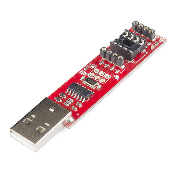
The Tiny AVR Programmer is a general AVR programmer, but it's specifically designed to allow quick-and-easy programming of ATtiny85's (as well as 45's) compared to the pocket AVR programmer. It has an on-board socket, where the little 8-pin IC can be plugged in and directly programmed. No messy wires or soldering required! Once you've programmed the ATtiny85, just remove it from the Programmer, and stick it into a breadboard or prototyping board.
The Tiny AVR Programmer can also be used as a general purpose AVR programmer. It can directly program almost all AVR's (including the ATmega328 and ATmega32U4) whether they're on Arduino boards or in a breadboard.
Covered In This Tutorial
In this hookup guide, we'll show how you can program ATtiny85's using the Tiny AVR Programmer and Arduino. We'll cover everything from driver installation to Arduino programming tips.
Required Materials
In addition to the Tiny AVR Programmer, you'll also need the following items to follow along with this tutorial:
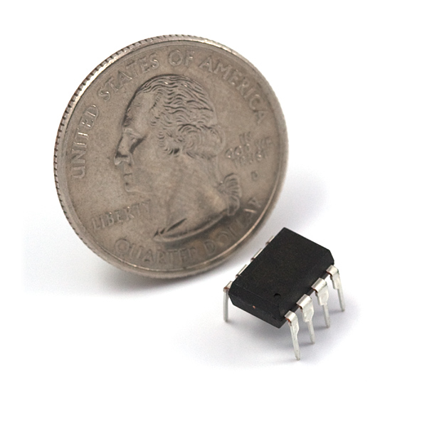
- ATtiny85 -- To be programmed by the programmer. Remember, you can also use this to flash other AVR chips like the ATtiny84!
- A computer or laptop with:
- A free USB Port. A USB hub should work too.
- Arduino IDE installed.
- Optional:
- USB Extension Cable -- If your USB port is out of reach, this may help make the Programmer easier to reach.
- IC Test Clip - SOIC 8-Pin -- If you are using a surface mount ATtiny, this handy dandy little clip makes it easy to program the microcontroller!
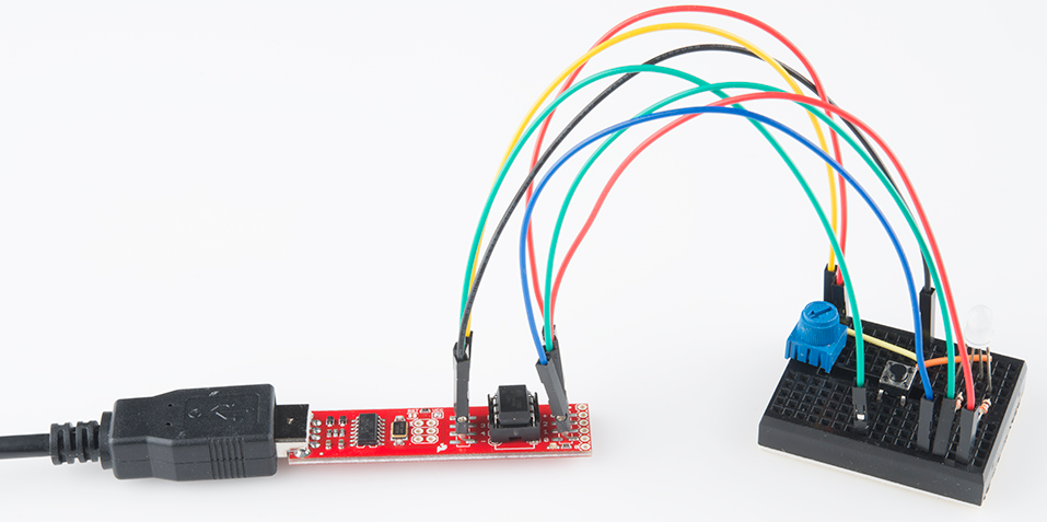
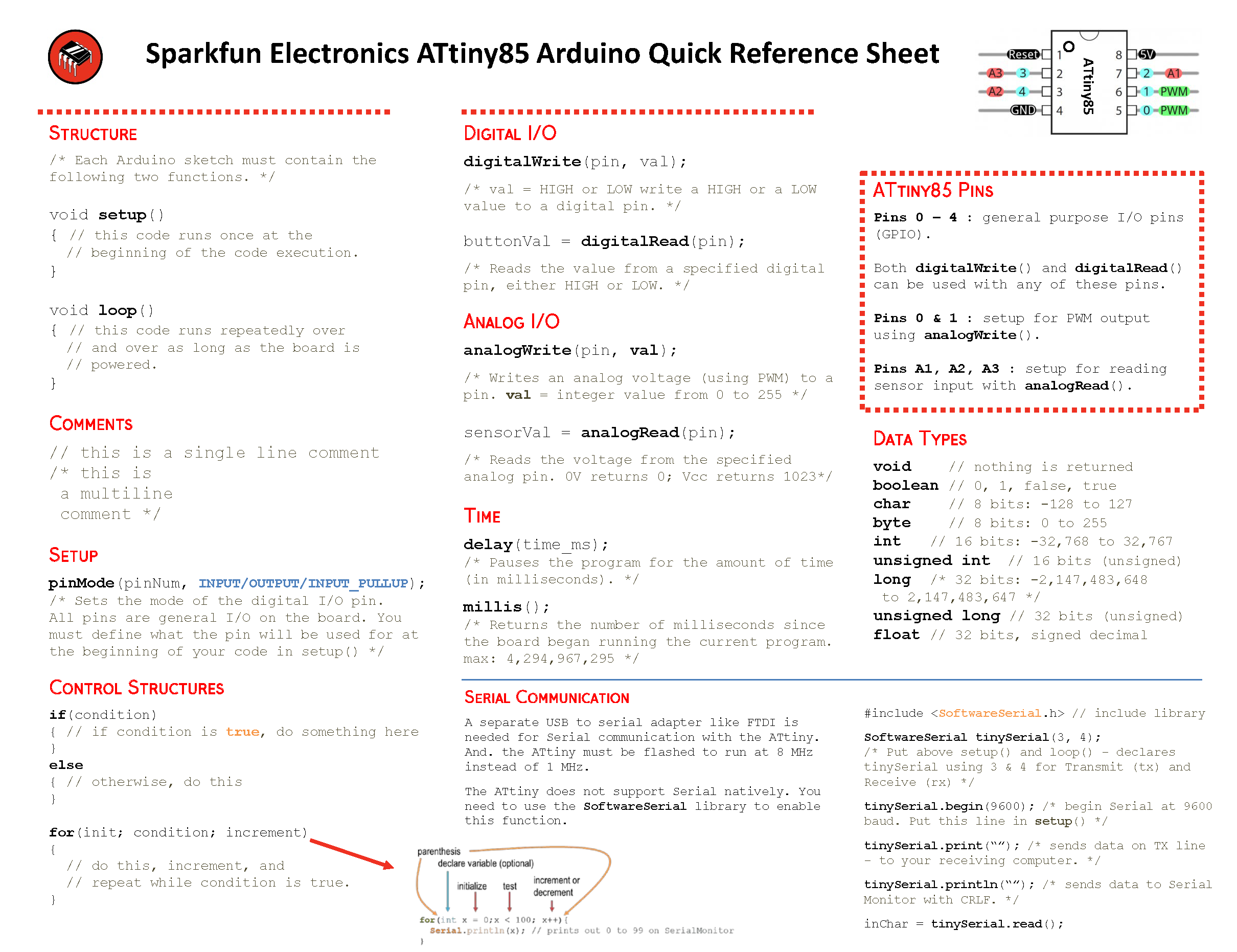
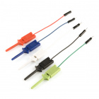
- Jumper Wires Premium M/F -- Useful if you are connecting the Tiny AVR Programmer to another AVR microcontroller that is not the ATtiny85 or the IC Test Clip.
Suggested Reading
- Installing Arduino -- You'll need Arduino installed for the Programming in Arduino section of this tutorial. There is an ATtiny85 addon for Arduino, which enables you to program the tiny AVRs in the familiar Arduino interface.
- Integrated Circuits -- This tutorial goes over the basic concepts of integrated circuits. The little black chips that the Tiny AVR Programmer is designed to program.
- Polarity -- Specifically the Integrated Circuits section. You should know all about IC notches and dots.
Installing Arduino IDE
Polarity
Integrated Circuits
Board Overview
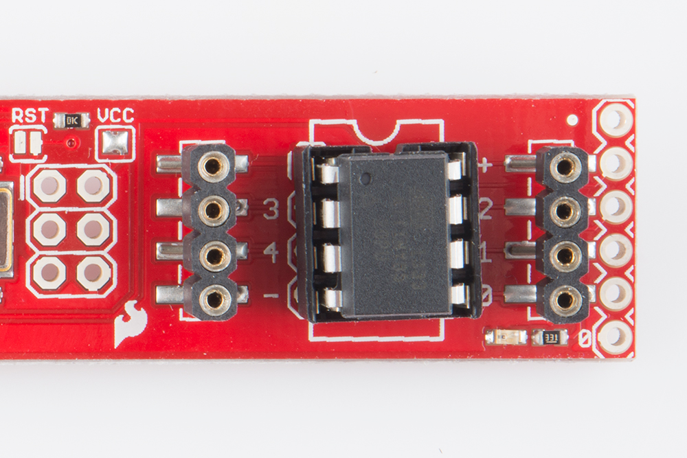
The image below provides a quick overview of the components on the Tiny AVR Programmer:
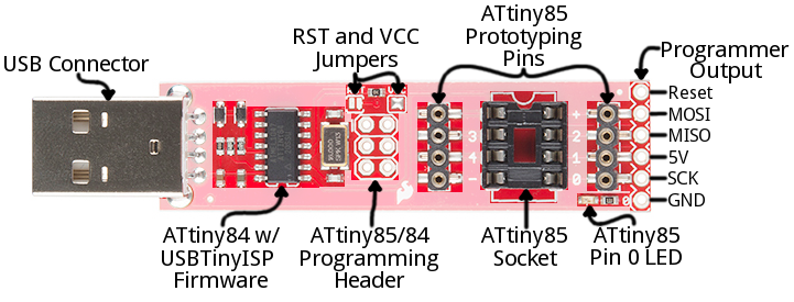
The "brain" of the Tiny AVR Programmer is an ATtiny84 (not to be confused with the 85), -- the 16-pin surface-mount chip -- which comes preprogrammed with some firmware that makes it look like an AVR programmer. Unless you're writing custom AVR ISP firmware, you shouldn't ever have to mess with this chip. It's a black box. Program data comes into it from your computer, over USB, and it spits out the proper sequence of bytes to load that program into your ATtiny85.
In this tutorial, we'll mostly concern ourselves with the components on the right half of the board. The ATtiny85 programming socket, pin 0 LED, and prototyping pins.
ATtiny85 Socket and Prototyping Pins
The socket and the pins broken out to the sides are what make the Tiny AVR Programmer unique. The 8-pin socket fits both the ATtiny85 and the ATtiny45 DIP packages. Just plug your IC-to-program into this socket, and a-programming you will go!
When plugging your ATtiny into the socket, take note of the notch on both the socket and the white silkscreen on the PCB. This should match the polarity of the ATtiny85. Usually the ATtiny85 has a dot next to pin 1 of the IC, this should be placed up towards the notch.
The +, -, and numerical labels on the side of the socket reference the pin numbers and voltage supply inputs of the ATtiny85. These pin numbers can be called in the Arduino IDE as we'll show later in this tutorial.
The 4-pin headers on either side of the socket help for prototyping the ATtiny85 out to external circuitry. You can easily plug male jumper wires into these pins, which can be routed to breadboards or other prototyping circuits.
The 4-pin headers can also be used to connect to surface mount ATtiny85's or other AVR microcontrollers that are on breadboards.
Finally, there's an on-board amber LED connected to pin 0 of the ATtiny85. This is super-helpful when you're uploading the "Hello, world" blink sketch to an ATtiny85.
That covers the fundamental stuff on the Tiny AVR Programmer. If you plan on doing more advanced stuff with the board, or just want to know more, feel free to read on. Otherwise, skip ahead to the next page.
Output Programming Pins
The Tiny ISP Programmer is not limited to ATtiny85's. It's a full-fledged AVR programmer. This row of six pins can be connected to other AVRs via the standard 2x3- or 2x5-pin ISP headers. You could, for example, connect these pins to your Arduino Uno, Leonardo, etc. to re-flash a bootloader, or upload code using a programmer.
Refer to the pin labels in the image above if you're connecting the Tiny AVR Programmer to another AVR chip. Most AVR development boards break out either a 2x3 or 2x5 programming header, which have the following pin-outs:
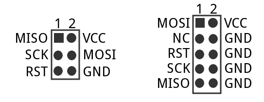
Just match up the labels on the Tiny Programmer to the pins on your AVR board/chip, and get ready to program!
The Jumpers
There are two jumpers on the top side of the Tiny AVR Programmer: one is labeled RST and the other is VCC. Both of these jumpers affect the unpopulated 2x3 ICSP (in-circuit system programmer) header in the middle of the board. Unless you're planning on reprogramming the on-board ATtiny84, these jumpers and pins can generally be ignored.
The VCC jumper is normally closed. It controls the flow of power to the VCC pin on the ICSP header. When closed, power from USB will flow to the ICSP header. When open you'll need to supply power externally to that pin.
The RST jumper is normally open. When closed, this jumper connects the ATtiny84's reset pin to the to the 2x3 programming header. If you ever need to reprogram the ATtiny84 (which, for standard use cases, you shouldn't), you'll have to close this jumper to enable programming it.
Enough talk. Let's start using the programmer. On the next few pages we'll cover driver installation (for Windows users) and show how you can use the Tiny AVR Programmer to program an ATtiny85 in Arduino.
Driver Installation
Before you can start using the Tiny AVR Programmer, you may need to set it up on your computer. If you're using a Mac or Linux machine, you don't need to install drivers. Just plug the board in, and skip to the Programming in Arduino page.
If you're using any version of Windows, you've got a few steps to follow before you can join your Mac/Linux comrades. There are two sets of instruction for driver installation on this page. The first is the easiest, quickest method, and should work for most everyone. The second installation process is only required if the first one fails -- it takes a more manual approach to the driver installation.
Automatically Install the Drivers with Zadig
To begin, plug the Tiny AVR Programmer into your computer. Upon initially connecting the board, Windows will try to automatically install the drivers. Some computers may be lucky, but most will turn up with a message notifying you that the driver install failed.
Click the link below to download the Zadig software and drivers:
Use your favorite unzipper to extract the ZIP file. Don't forget where you put the extracted folder!
After you've plugged the Tiny AVR Programmer into your computer and your machine has run through the process of checking for and failing to install drivers, proceed to the "zadig_v2.0.1.160" folder you just unzipped. Then Run zadig.exe software.
Zadig is a wonderful tool that can install the drivers on just about any Windows platform out there. Upon opening the program, you should be greeted with a window like this:
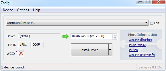
There are a few options to verify before installing the driver:
- Select the device -- The top dropbox controls which device you want to install the driver for. Hopefully you only have one option here, something like "Unknown Device #1". If you have more than one option, check your device manager to see if you can make sense of which is which (plugging and unplugging a device usually helps).
- Select the driver -- Click the arrows in this box until you happen upon libusb-win32 (vx.x.x.x), that's the driver we want to install.
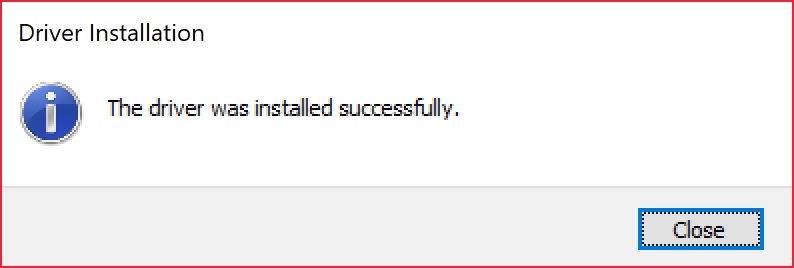
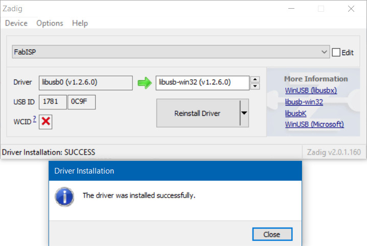
After verifying those two selections, click "Install Driver". The installation process can take a few minutes, but after you've watched the scroll bar zoom by countless times, you should be greeted with a "The driver was installed successfully" message.
Zadig Driver Installation Issues
After installing the drivers, your computer may respond by indicating that the device was not installed correctly. Here are two methods of troubleshooting driver issues when installing with Zadig.📌 Troubleshooting Tip: In this case, the WinUSB drivers were selected instead of the libusb-win32 drivers. To remedy the issue, simply go through the guide again to reinstall the correct libusb-win32 drivers.
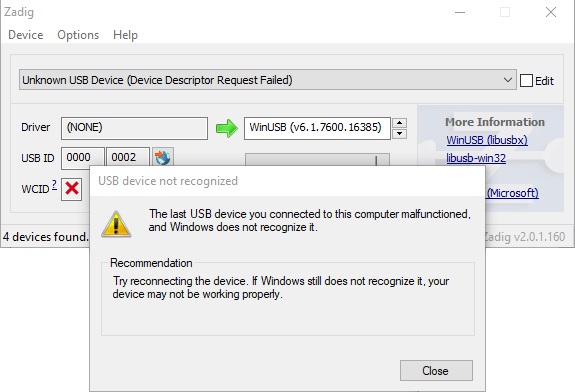
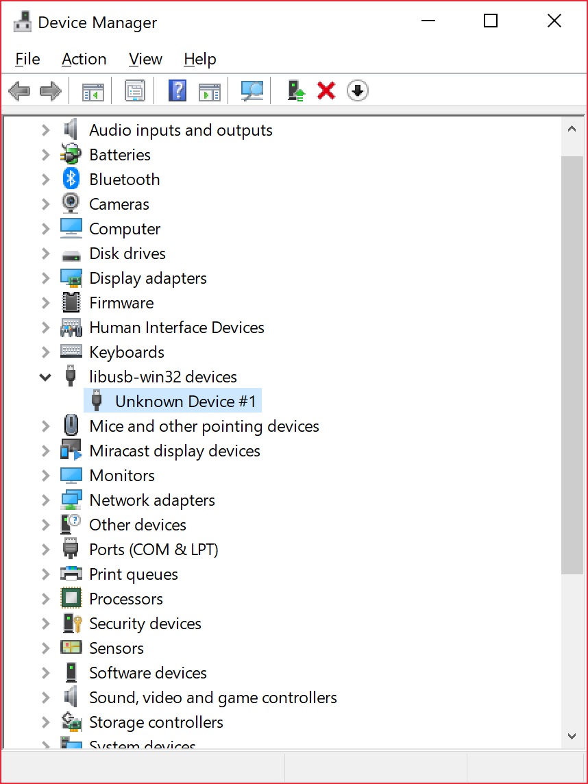
📌 Troubleshooting Tip: In other cases, it may also initialize somewhere in your device manager as an Unknown USB Device (Device Descriptor Request Failed) even if you installed the correct drivers:
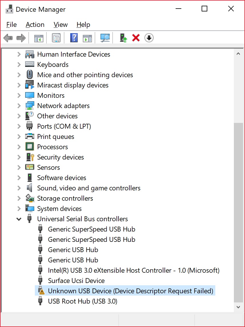
Try unplugging and replugging the Tiny AVR Programmer back into your USB port. Or switch out your USB extension cable for a known good. In some cases, your Tiny AVR Programmer may shows up under the libusb-win32 devices as an Unknown Device #1. If that is the case you should be good to go!
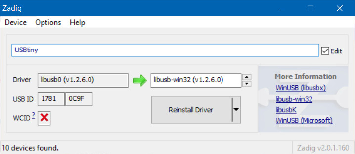
Type in the name for your port. It can be "USBtiny" or in this case. Make sure that the correct driver is selected.
Click Reinstall Driver. The driver will reinstall and you should see the same message that indicates that the drivers were successfully installed. You may need to unplug and replug the programmer to your computer to give it a second to refresh again.
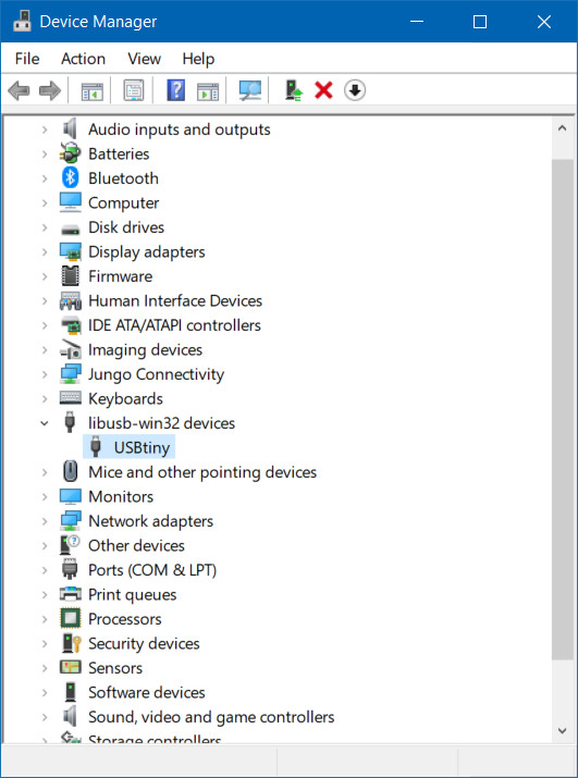
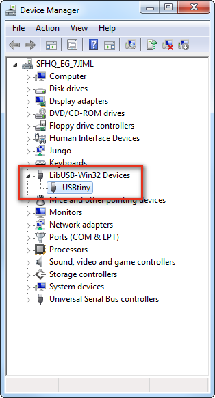
Open up your device manager and you should see the device renamed!
If you were successful, close out of the Zadig program and proceed to the next section!
If Zadig didn't work for you, check out the instructions below for help manually installing the drivers.
Manually Installing the libUSB Drivers
Step 1: Plug the Programmer In
To begin, locate an empty USB port on your computer, and plug the Tiny AVR Programmer into it. You'll probably want to have the programmer close by. If you're using a PC, or your USB ports aren't close by, a USB Extension Cable might help get the programmer into a more convenient spot on your desk.
Step 2: Wait for Windows to Automatically Fail/Succeed
After plugging in your Tiny AVR Programmer, Windows will try to look for a driver that matches it. Keep an eye on the notification area in the bottom-right corner. Wait for Windows to try to install the driver on its own. There's a chance that, after searching, Windows will find the driver. If you get a Device driver software installed successfully notification (lucky you!), you can ignore the next few steps. But, if you got something like this:
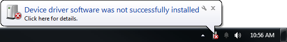
Continue on to step 3...
Step 3: Download the Driver
If Windows couldn't find the driver for you, you'll need to download it. You can head over to the Tiny AVR Programmer GitHub repository and grab what you need there, or you can click the link below to download the zip file directly.
After downloading your driver, extract it from the zip folder. Don't forget where you put it!
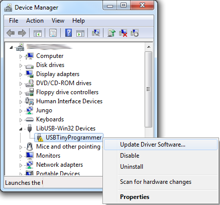
Step 4: Open the Device Manager
To install the driver, you'll need to first open up the Device Manager. From the Control Panel, go to the System and Security section, click System, and click on Device Manager. (Alternatively you can Run devmgmt.msc).
In the Device Manager, open up the LibUSB-Win32 Devices tree and you should find a USBTinyProgrammer with a yellow warning triangle hovering over the icon. This also may be located in "Other devices > Unknown device.
Right-click on the USBTinyProgrammer device, and select Update Driver Software...
Step 5: Driver Pointing
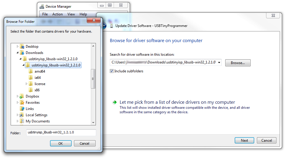
On the Update Driver Software window that appears, select Browse my computer for driver software.
On the next window, Browse for driver software on your computer, set the driver search location to the folder you downloaded and unzipped in step 3.
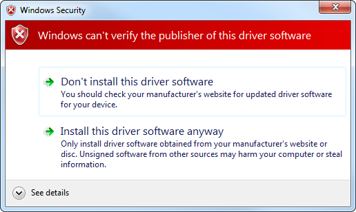
Then click Next, and the driver will begin updating. Shortly after that, though, a Windows Security window should pop up to let you know the driver isn't "signed". Click Install this driver software anyway. We promise it won't damage your computer!
Then play the waiting game for a moment, and wait for a happy Windows has successfully updated your driver software window.
After closing that success window, your Device Manager should have an entry for USBtiny under LibUSB-Win32 Devices.
Congratulations! Proceed over to the next section, and we'll start using the Programmer!
Breathe easy now! Once you've installed the USBtiny drivers on your computer, you shouldn't ever have to do it again. Now it's time to program something!
Programming in Arduino
Everyone loves Arduino! The simplified language makes programming AVRs and more complicated microcontrollers incredibly easy. Unfortunately, Arduino doesn't have any built-in functionality to program tiny AVRs, but that doesn't mean we can't add it!
On this page we'll go over all of the steps necessary to enable ATtiny45/85 programming in Arduino, using the Tiny AVR Programmer.
Step 0: Install Arduino
If you've never used Arduino before (where have you been?!), make sure you follow our What is an Arduino? and Installing Arduino tutorials before continuing on.
What is an Arduino?
Installing Arduino IDE
Step 1: Installing the ATtiny Add-On
The next step is to install the Attiny addon. The following steps in 1a and 1b will explain how to manually install the ATtiny board files for Arduino.
Step 1a: Download the ATtiny Addon
To manually add ATtiny's to the standard Arduino IDE Board menu, you'll need to add a few files that help define the hardware. The latest ATtiny hardware definitions are kept in a repository on GitHub.
You can download them from there, or simply click on the archived links below (note: There are different files depending on which version of Arduino you are using):
Extract the ZIP folder, and don't forget where you put it!
Step 1b: Move the attiny Folder
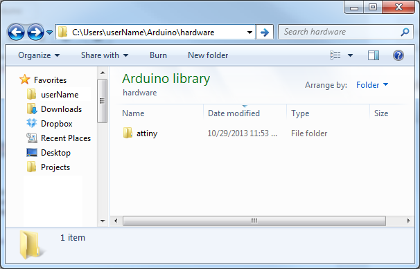
There should be an attiny folder living within the attiny-ide-1.x.x.zip file you downloaded. Copy that folder and paste it into a folder called hardware within your Arduino Sketchbook directory.
If you're not sure where your Arduino sketchbook is, open Arduino and go to File > Preferences. The Sketchbook location should be the topmost entry in the Preferences dialog. By default, the sketchbook is usually an Arduino folder within your home folder (e.g. C:\Users\userName\Arduino on Windows, or /Users/userName/Documents/Arduino on Mac).
If there's not a hardware folder already in your Sketchbook make one. After placing the attiny folder in there, your directory structure should look a little something like this:
Step 2: Open and Configure Arduino
Almost to the fun part! Open Arduino. If you opened Arduino in the last step, close it and restart it.
Under the Tools > Board menu, you'll find the effects of the attiny folder. There should be twelve new entires in the board list, which allow you to program ATtiny45's, 85's, 44's and 84's. Each microcontroller can be set to a variety of clock speeds -- internal 1MHz or 8MHz or external 20MHz.
If you're using a bare, previously untouched ATtiny85 select ATtiny85 (internal 1 MHz clock). Be careful selecting here, selecting the 8 MHZ option will only make your sketch run slow, but selecting the 20 MHz option can "brick" your ATtiny. Do not select the 20 MHz option unless you have an external clock attached!
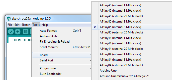
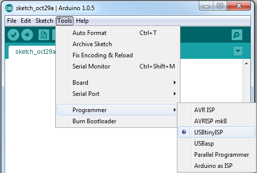
Unlike other Arduino boards, you don't have to select a Serial Port when using the Tiny AVR Programmer. But you do need to select a Programmer. Under the Tools > Programmer menu, select USBtinyISP.
Step 3: Plug in the ATtiny
Getting close to blinking! When you plug the ATtiny into your Programmer, make sure you get the polarity correct. The small, etched circle on the IC should line up with the "notch" on the Programmer's socket and silkscreen.
To get the IC into the socket, you may need to bend the legs on each side inwards a tad.
Step 4: Upload Code!
Time for the Blink sketch! The Tiny AVR Programmer has an on-board LED, connected to the ATtiny, which we can use to verify that code on the IC is running. The LED is connected to pin 0 in the Arduino environment. Copy/paste this code into your Arduino window:
language:c
int blinkPin = 0;

void setup()
{
  pinMode(blinkPin, OUTPUT);
}

void loop()
{
  digitalWrite(blinkPin, HIGH);
  delay(500);
  digitalWrite(blinkPin, LOW);
  delay(500);
}
Then click the Upload button just as you would with any Arduino board. The code will compile, and then it should upload insanely fast. That's the wonders of direct in-system programming for you. If successful, the on-board amber LED should start blinking.
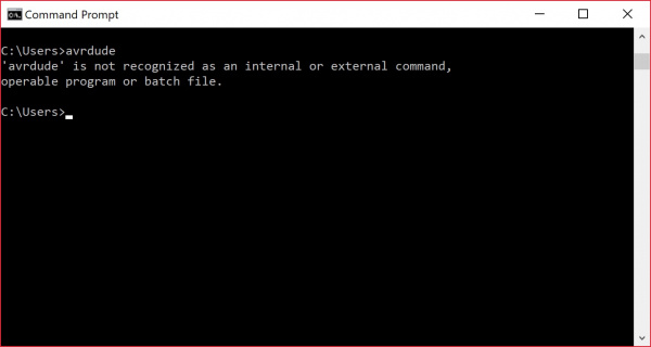
avrdude: Error: Could not find USBtiny device (0x1781/0xc9f)
If the issue is related to the connection, try unplugging/replugging the AVR programmer back into your USB cable or USB port. You also want to try a different USB cable.
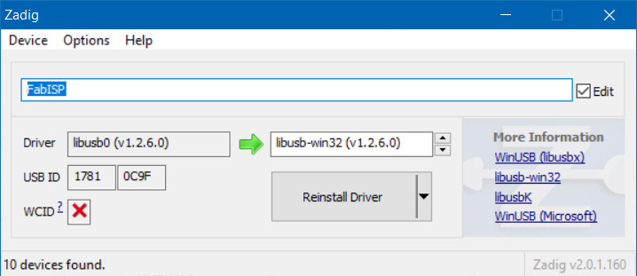
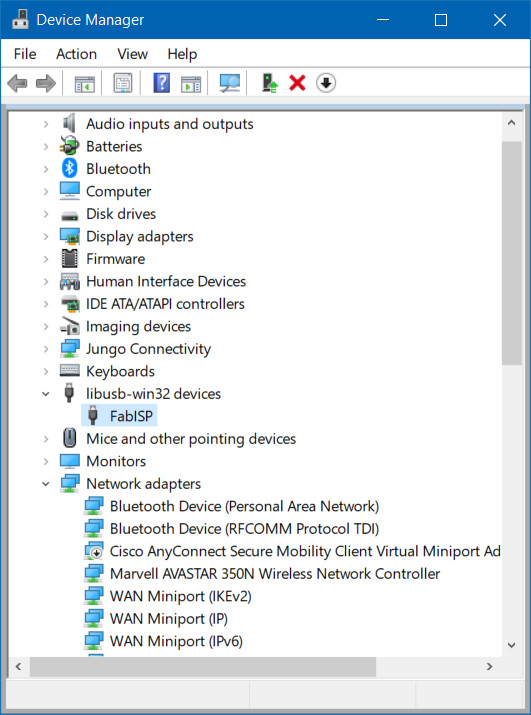
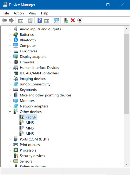
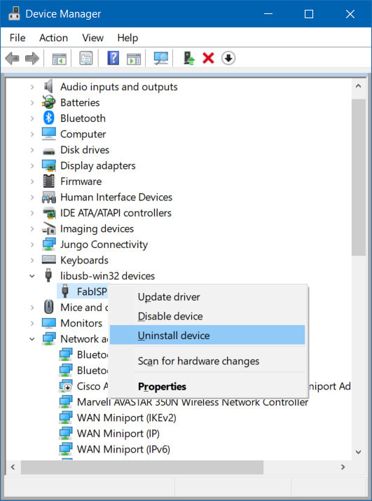
Otherwise, the issue may be due to the drivers. This may be caused by the driver not being installed correctly, or there is a driver conflict. Open up your device manager to view the device. The image on the left shows the device showing up as the libusb-win32 devices > FabISP. The image on the right shows the device showing up as Other devices > FabISP.
 |
 |
| Conflicting Driver | Driver Not Installed |
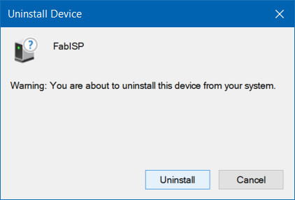
You may see a window pop up similar to the image below. Click on the button labeled Uninstall. In some cases, Windows may provide an option to "Delete the driver software for this device." if the option is provided, simply mark the checkbox before clicking on the button to uninstall.
Unplug and replug the AVR programmer back to your computer's USB port. Head back to the Driver Installation section and follow the instructions to Automatically Install the Drivers using Zadig.
Uploading Code the Hard Way
If you’re looking for more control over your Tiny AVR Programmer – and the AVR it’s connected to – follow along the tutorial for the Pocket AVR Programmer. While the tutorial was written for the Pocket AVR Programmer, it is functionally the same for the Tiny AVR Programmer. Just make sure to connect to the respective ICSP pins on the target AVR chip.
ATtiny85 Use Hints
The ATtiny85 isn't your everyday Arduino IC. It packs a lot of punch for its small size, but there are some things it can't do.
On this page, we'll provide a quick overview of the ATtiny85 as it pertains to Arduino and the Tiny AVR Programmer.
Pinout
Just like any Arduino board, each I/O pin on the ATtiny85 is assigned a numerical identifier. These pins are documented on the board as well, but you can also refer to the image below if you forget.
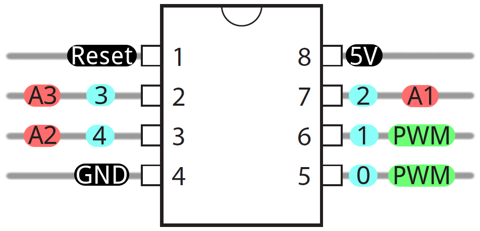
Each of the I/O pins on the ATtiny85 are capable of digital input and output. Beyond that, some pins have special functionality.
Analog Input and Output
There are two analog outputs and three analog inputs. Use them just as you would with any Arduino board. Use analogWrite([pin], [0-255]) to do PWM output. This functionality is available on pins 0 and 1. For example:
language:c
int pwmPin = 0;

pinMode(pwmPin, OUTPUT);

for (int i=0; i<=255; i+=5)
{
  analogWrite(pwmPin, i);
  delay(5);
}
And use analogRead([pin]) to read an analog voltage between 0 and 5V, and turn it into a 10-bit representation of that voltage. Pins 2, 3, and 4 are capable of analog input, but, when using them as such, they should be referenced as A1, A3, or A2 respectively. For example:
language:c
int pwmPin = 0;
int analogInPin = A1;

pinMode(pwmPin, OUTPUT);
pinMode(analogInPin, INPUT);

int analogIn = analogRead(analogInPin); // Read analog voltage on pin 2 (A1)

analogWrite(pwmPin, analogIn / 4); // Output analog reading to dimmable LED
If you need to reset the chip, simply use the erase command with the Tiny AVR or Pocket AVR Programmer via command line to get it back to its previous state. Uploading code with the Arduino IDE will not be enough. Here is an example using the fuse bit settings for the LilyTwinkle's ATtiny85:
avrdude -c usbtiny -b 19200 -p t85 -v -e -U lfuse:w:0xe2:m -U hfuse:w:0xdf:m -U efuse:w:0xff:m -U lock:w:0xCF:mNo Serial (UART). Yes SPI and I2C.
You may notice, on the listing of special pin functions there are no UART RX's or TX's. That's because the ATtiny85 doesn't have a built in hardware UART. If you try to compile any Arduino code with Serial.begin(9600)'s or Serial.print()'s you'll get an error.
So you're out one of the more useful Arduino debugging tools. You can't print to the Serial Monitor. But the ATtiny85 does still have I2C and SPI, which are much more commonly used for sensor communication these days. Unfortunately, the Arduino libraries for these interfaces haven't yet been written for the ATtiny85, but there are some user contributed libraries around the web. USIi2c is an Arduino library which enables I2C on the ATtiny85.
There are other ATtiny85-focused libraries out there too. Like a Servo8Bit, a servo library.
Prototyping with the Tiny AVR Programmer
There's only so much excitement you can get out of dimming a single, yellow LED. You'll eventually want to branch out, and start connecting your tiny85 to other electronic components. There are a few ways to do this.
The easiest, least permanent prototyping route is to use the prototyping headers on either side of the socket. You can connect standard, male jumper wires to these pins, which can in turn be routed to breadboards or other components.
For more permanent projects, it's easy enough to gently remove the IC from the socket, and plug it into a PCB or breadboard. Eventually, once you've iterated enough on your sketch, this is probably where you'll want to go. Eventually you arrive at finished designs like the H2OhNo! or the LectroCandle.
Surface Mount ATtiny85 SOIC Packages
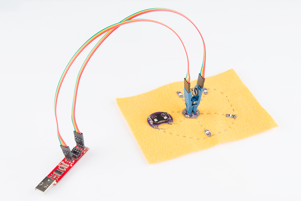
Trying to reprogram an ATtiny85 with a SOIC Package? There are a few ways to connect. The easiest would be to use the IC test clip and M/F jumper wires.

For more information, check out our tutorial on reprogramming ATtiny85's on the LilyTiny and LilyTwinkle.
Re-Programming the LilyTiny / LilyTwinkle
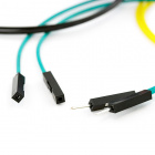
If the programming pins are broken out on a standard 2x3 ICSP header, you could also solder together the ISP pogo adapter to temporarily connect to the chip. Or you could grab a few alligator test leads or IC hook to individually connect each programming pin to the Tiny AVR Programmer's machine headers.
Resources and Going Further
Now that you've successfully got your Tiny AVR Programmer up and running, it's time to incorporate it into your own project!
For more information, check out the resources below:
Tiny AVR Programmer Design Files
- Schematic -- A PDF of the Tiny AVR Programmer's schematic.
- Eagle Files -- If you want to look at the PCB design, or modify it to make a version of your own, check these files out.
- Tiny AVR Programmer Firmware -- If you want to dig into the code that lives on the Programmer itself, check this out.
- GitHub Repository -- Go here to find the latest, greatest version of the Tiny AVR Programmer's hardware and firmware. Or modify it and contribute your changes back!
Drivers, etc.
- Arduino Board Definitions -- The attiny folder should live within a hardware folder in your Arduino sketchbook.
- Zadig v2.0.1.160 Software and USBtiny (ZIP) -- For automatic installation
- 32-bit USBTinyISP Driver -- Windows driver for manual installation on 32-bit systems
- 64-bit USBTinyISP Driver -- Windows driver for manual installation on 64-bit systems
- GitHub: Signed USBTiny Drivers -- If the first 3 options listed in the tutorial fail to install fail to install
- ATtiny85 Resources
- Atmel Documentation Page -- The latest datasheets and application notes for the ATtiny85.
- High-Low Tech Tutorial -- An overview of programming the ATtiny85 using Arduino.
- Quick Reference Guide for ATTiny85
Need some inspiration for your next project? Check out some of these related tutorials:
- H2OhNo! -- The H2OhNo! water alarm and development board uses an ATtiny85 to sense the presence of water. This tutorial goes deep into getting the ATtiny85 into a very low power mode.
- Shift Registers -- If you're feeling restrained by the ATtiny's lack of pins, you may be able to use a shift register to expand on that I/O count.
- Using the Arduino Pro Mini 3.3V -- If you're looking for small, but need more pins and functionality check out the Arduino Pro Mini.
- Installing an Arduino Bootloader -- You can use the Tiny AVR Programmer to program all sorts of AVRs, including those on most Arduino-compatible boards. If you ever find yourself needing to reprogram your Arduino bootloader, the Tiny AVR Programmer should be all you need.
- Pocket AVR Programmer Hookup Guide -- If you are interested in using the Tiny AVR Programmer to program other AVRs with AVRDUDE via command line, this tutorial will provide a few examples and troubleshooting tips. Just make sure to connect to the respective ICSP pins.
Installing an Arduino Bootloader
Shift Registers
Using the Arduino Pro Mini 3.3V
Pocket AVR Programmer Hookup Guide
Or check out these tutorials using the Attiny.
The Uncertain 7-Cube
Atto84 Hookup Guide
SparkFun Qwiic Button Hookup Guide
SparkFun Qwiic Quad Solid State Relay Kit Hookup Guide
Are you looking to use a Pi to flash larger file sizes to your AVR microcontrollers? Try checking out the Pi AVR Programmer Hat!