Simon Tilts Assembly Guide
 QCPete
Prototyping the Tilt Arm Sensors
Pictured below is one of our early prototypes for the Simon Tilts design. As you can see with all of the hand wiring, sometimes it takes more than a few tries to find the best solution.

You can see two of our initial approaches to sensing the tilt position. The first one you may notice is the three tilt sensors:

In this approach, we are using our Tilt Sensors.
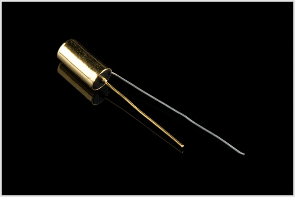
Each of these has a little metal ball inside that closes or opens a switch between the two leads. In this way of using a falling ball within a cylinder, it is very similar to our final Tilt Arm approach. The only difference is that the standard tilt sensor was not reliable enough for our application. We were getting very inconsistent readings from each sensor. Plus, the legs of those tilt sensors are pretty thin wire, and so after a little fumbling around, they would bend out of position.
The second approach that you can see in the above prototype is using hall effect sensors, magnets and white plastic tubes. This method actually proved to be very reliable and consistent. The only downside was that it was much more expensive and would require sourcing tubing and/or getting a custom molded cylinder part made.
Both of these approaches had one more down side: they required the user to precisely bend the sensor to a 45 degree angle. We found that if this angle was just slightly off, then the sensor would begin malfunctioning. So we continued to brainstorm for a solution that would avoid this problem.
With another prototype we used out Tilt-a-Whirl Breakout - RPI-1031.
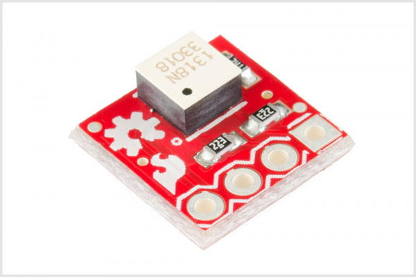
It worked pretty well, but we wanted to keep this design 100% PTH parts. Also, it required two of them, which would add to the cost. Also, (just like the other tilt solutions, they had to be positioned at a 45 degree angle, which meant bending headers or tricky soldering.
During all of our prototyping, the accelerometer BOB was actually an option in the back of our minds. Our Triple Axis Accelerometer Breakout - MMA8452Q would work well for this application.
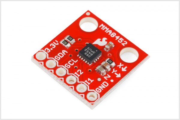
There was one problem with using a breakout board: the sensor itself is not a PTH part. Although we could include a footprint on the PCB to mate with the accelerometer's pinout, we were hesitant to use this approach. Adding one more "black box" to the project can increase the barrier to understanding a technology for a newbie.
Ultimately, we opted to create our own unique custom molded part:
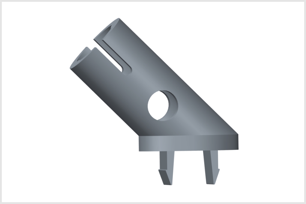
It uses an IR emmitter and detector in order to know the position of the BB ball inside the cylinder. The IR emitter and detector are positioned so that the IR beam "shoots" through the hole in the bottom of the cylinder. When the BB is resting at the bottom of the cylander, then it is blocking the IR beam. When the BB is resting at the upper end of the tilt arm, then the "look-through" hole is unobstructed, and the IR detector can sense the emitter.
In order to make using this part easier, we created a device in our Eagle Library:
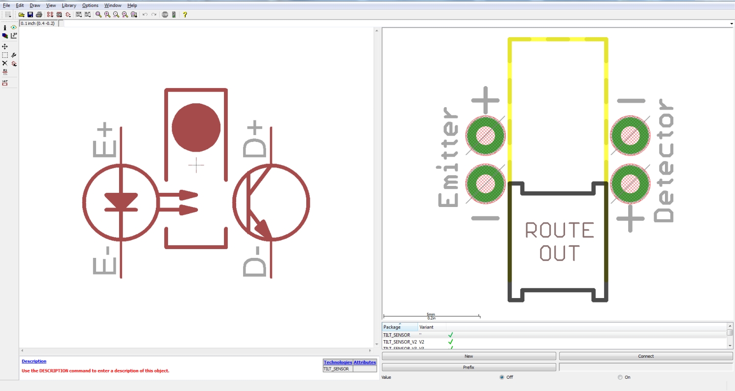
The package includes the correct positioning of the emittor, detector and dimension route out area to mate with the tilt arm part. An important thing to note is that when choosing a pull-up resistor for the detector line, we found that 330 ohms was the best value. This value is used in the kit. We first tried using the internal pullups on the ATmega328, but the voltage swing from the detector was very minimal which made it hard to get accurate readings.
We'd like to send a huge thank you to Modrobotics, because they printed three rounds of prototypes for us!
We'd also like to thank Mountain Molding for all their help with design, tooling, and manufacturing the part!