Simon Tilts Assembly Guide
 QCPete
IR Emitters and Detectors
Careful, these next 6 parts are polarized and need to be placed into the PCB properly. To learn more about polarization, please check out this other tutorial: Diode and LED Polarity
Locate the IR emitter and detector pairs:

There should be 6 total pieces. Three with red dots, and three with yellow dots:
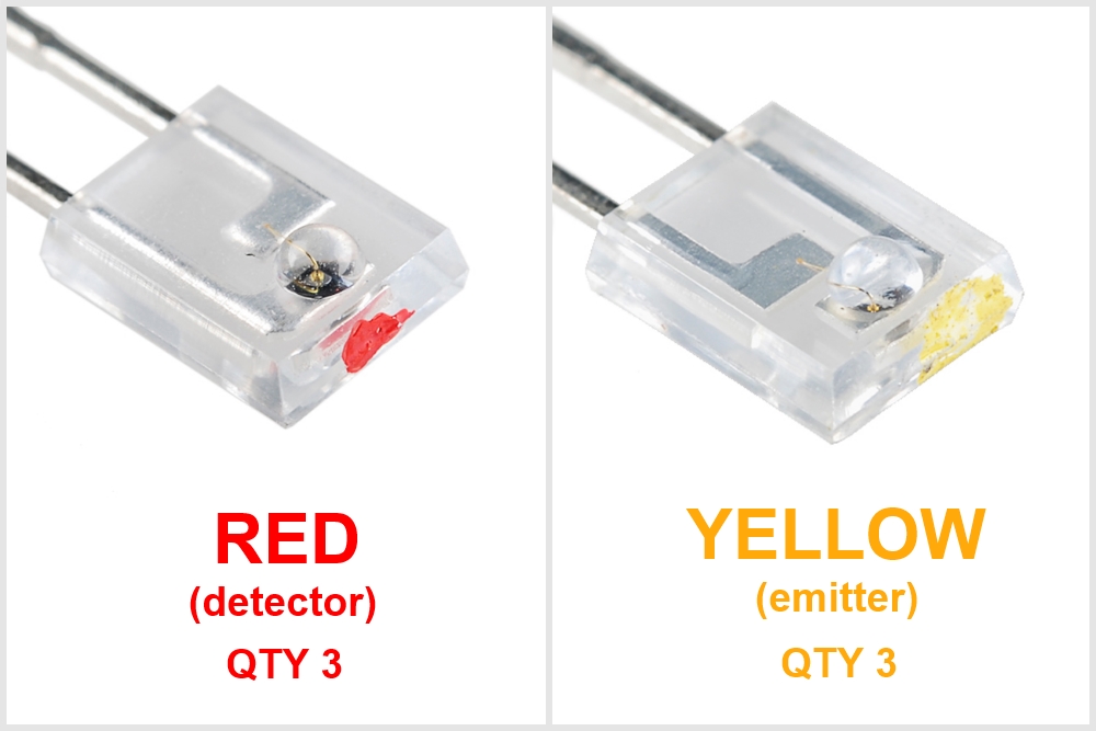
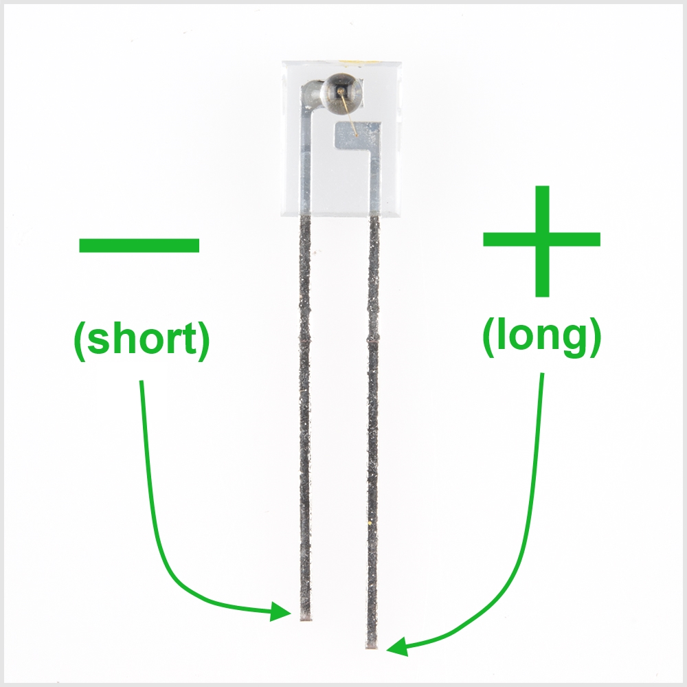
These are polarized parts, so this means they have a "-" and a "+" leg.
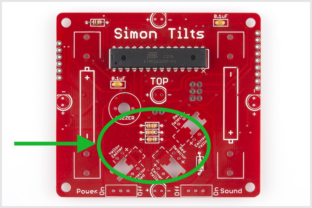
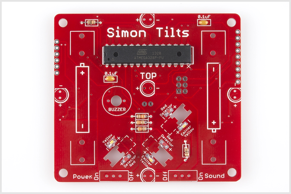
Locate the positions on the board. Notice that there are "Yellow Emittor" and "Red Detector" labels printed on the PCB. Also note that there are "-" and "+" marks for each leg. Be careful here to ensure correct placement and polarity.
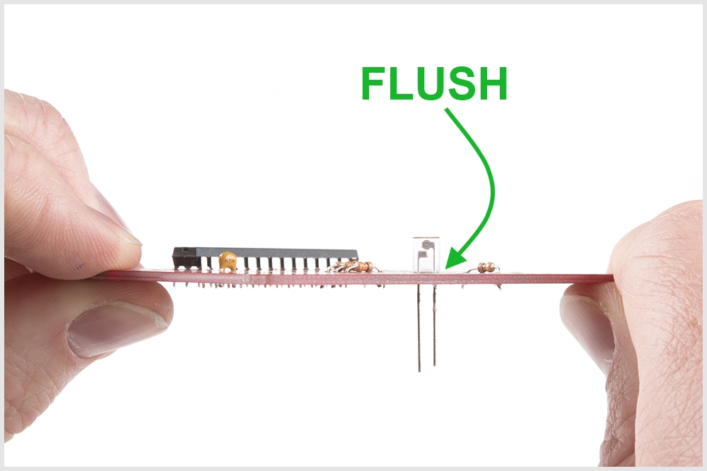
When soldering these into place, make sure they are positioned straight up (vertically). Check that your legs are forming a 90 degree angle with the PCB like so:
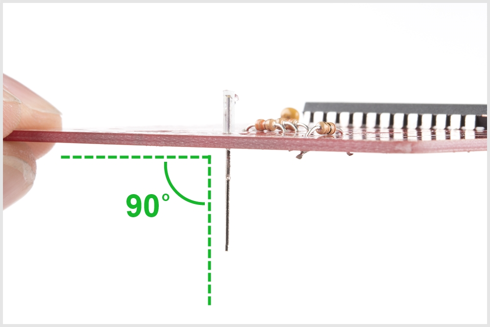
Also ensure that they are flush to the PCB:
When you're done soldering all 6 into place, your PCB should look like this:
To learn more about how IR emitters and detectors work, check out this video: SparkFun Infrared Sensor Overview