ReconBot with the Tessel 2
 rwaldron
Build It
To construct the robot, we'll put the chassis partially together and wire up a motor circuit. Then we'll install the robot's software and test the motors before completing the chassis construction.
Constructing the Chassis Base
Connect Motor Mounts
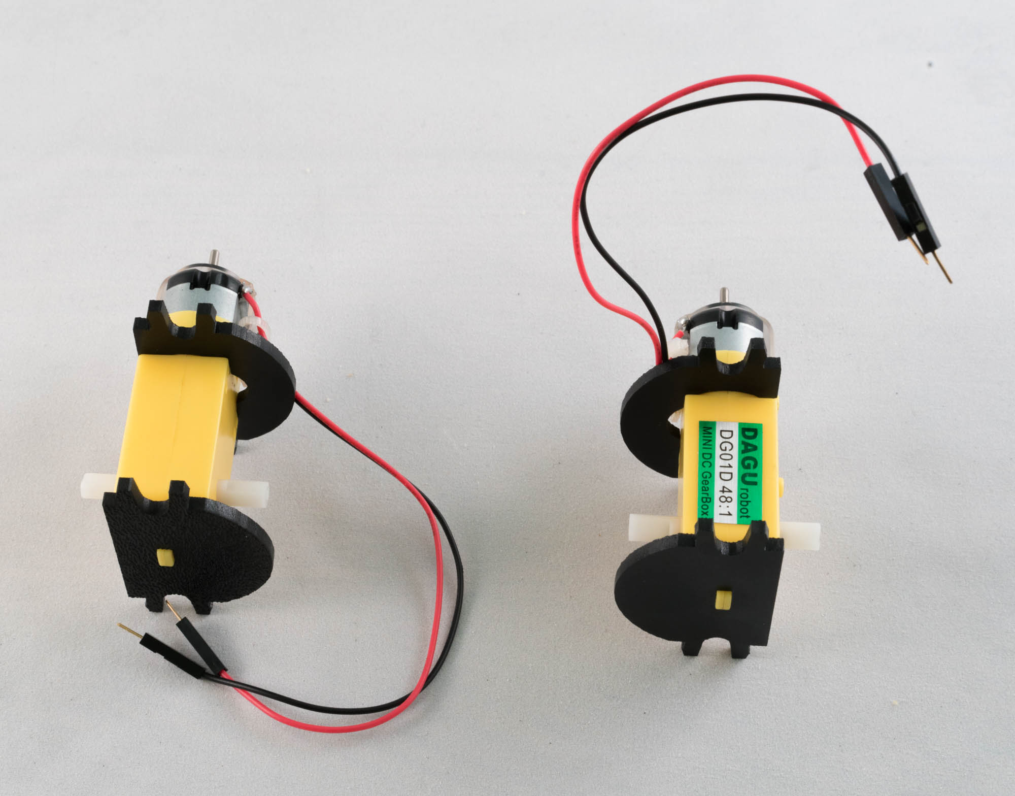
Each of the robot's two motors will have two supporting plastic mounts from the Shadow Chassis kit: one near the front of the motor and one at the back. When attached, the motor mounts will look like this:
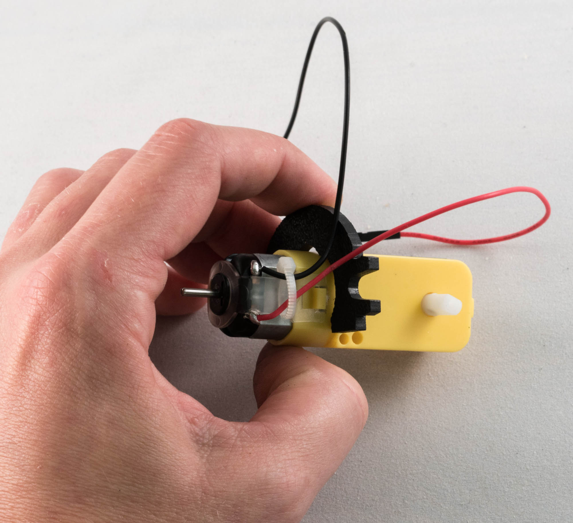
The back mounts are easy to attach—they just slide on. The front mounts require a quarter-turn to attach. Start by positioning the front mount as shown in the photo below, taking care not to pinch the motor's wires underneath the mount. Note the position of the motor's protruding white plastic axle to help you orient the motor.
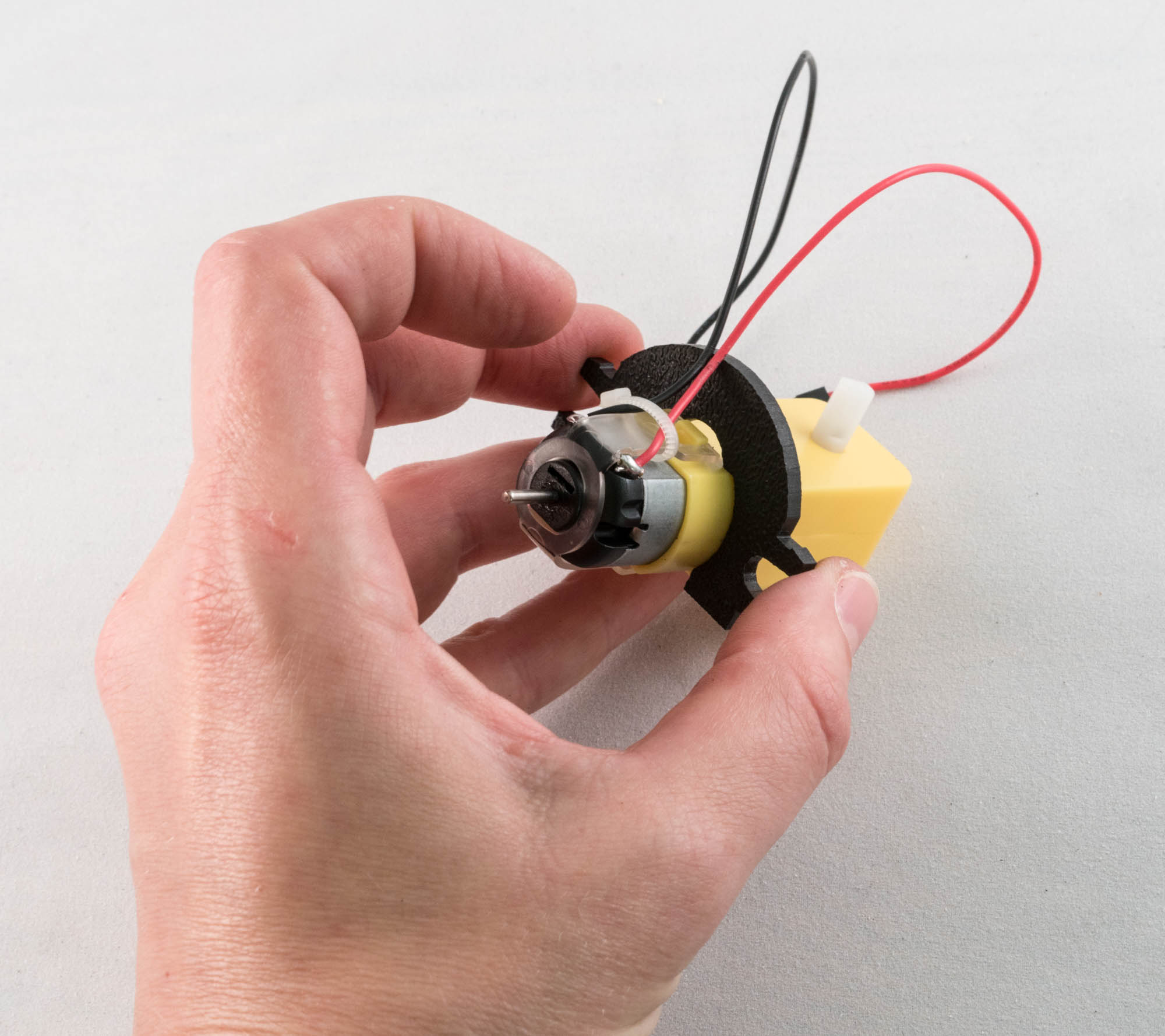
Now, rotate the mount counter-clockwise 90 degrees until it clicks into place around the motor. After it's secured, it should be positioned as in the photo below:
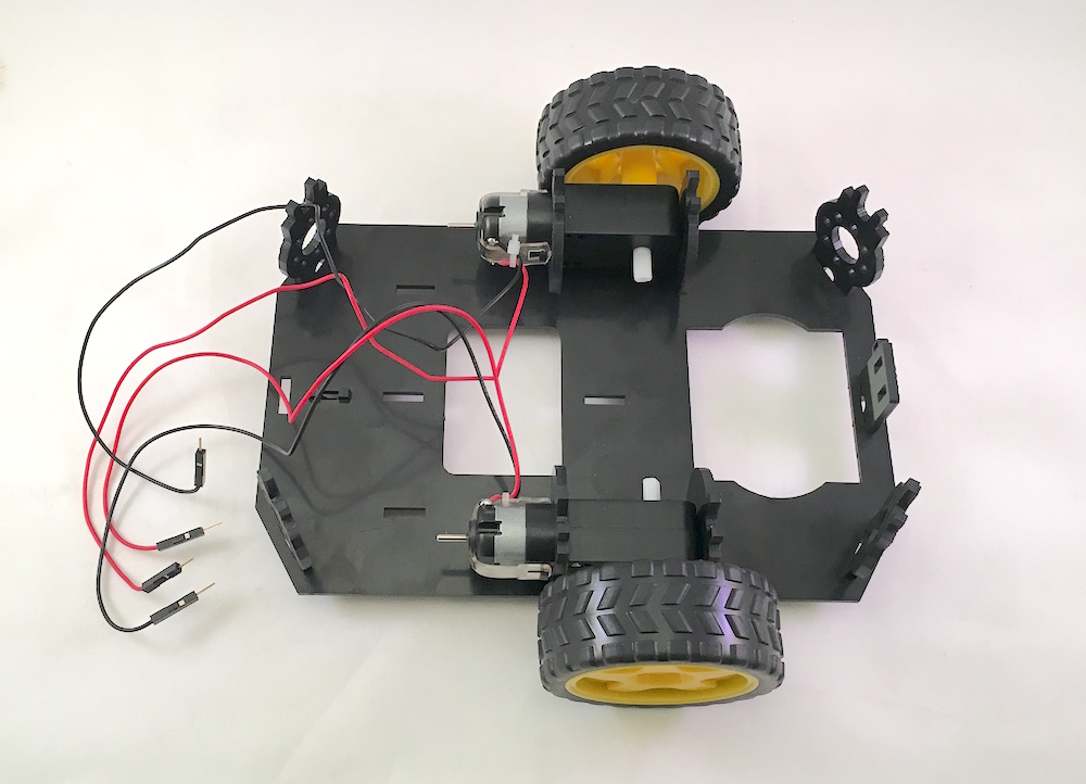
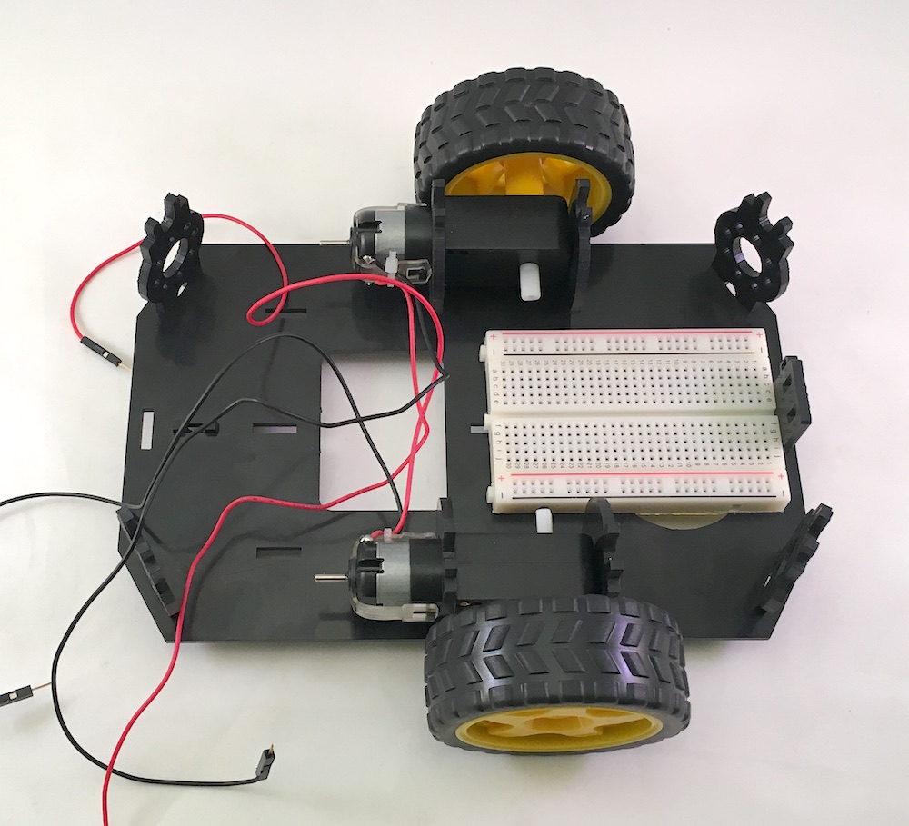
Now you can construct the chassis base:
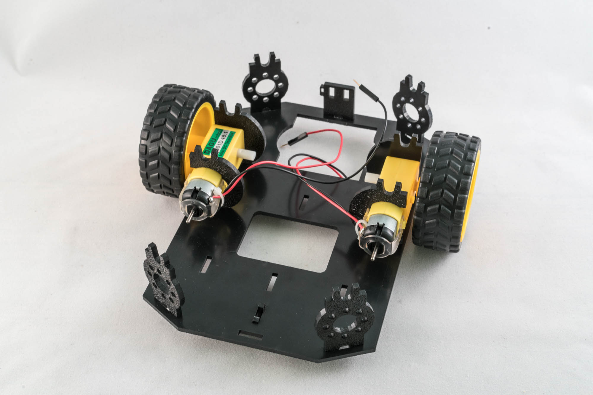
- Connect the mounted motors to the chassis by snapping the mounts into the chassis base. Pay attention to the orientation. The wires should be on the inside and the rear mounts of the motor should be toward the front of the robot (at the top in the preceding photo).
- Connect the struts at each of the four corners. Push hard to snap into place. Attach an extra support piece at the front of the robot for stability.
- Attach the wheels to the motor axles.
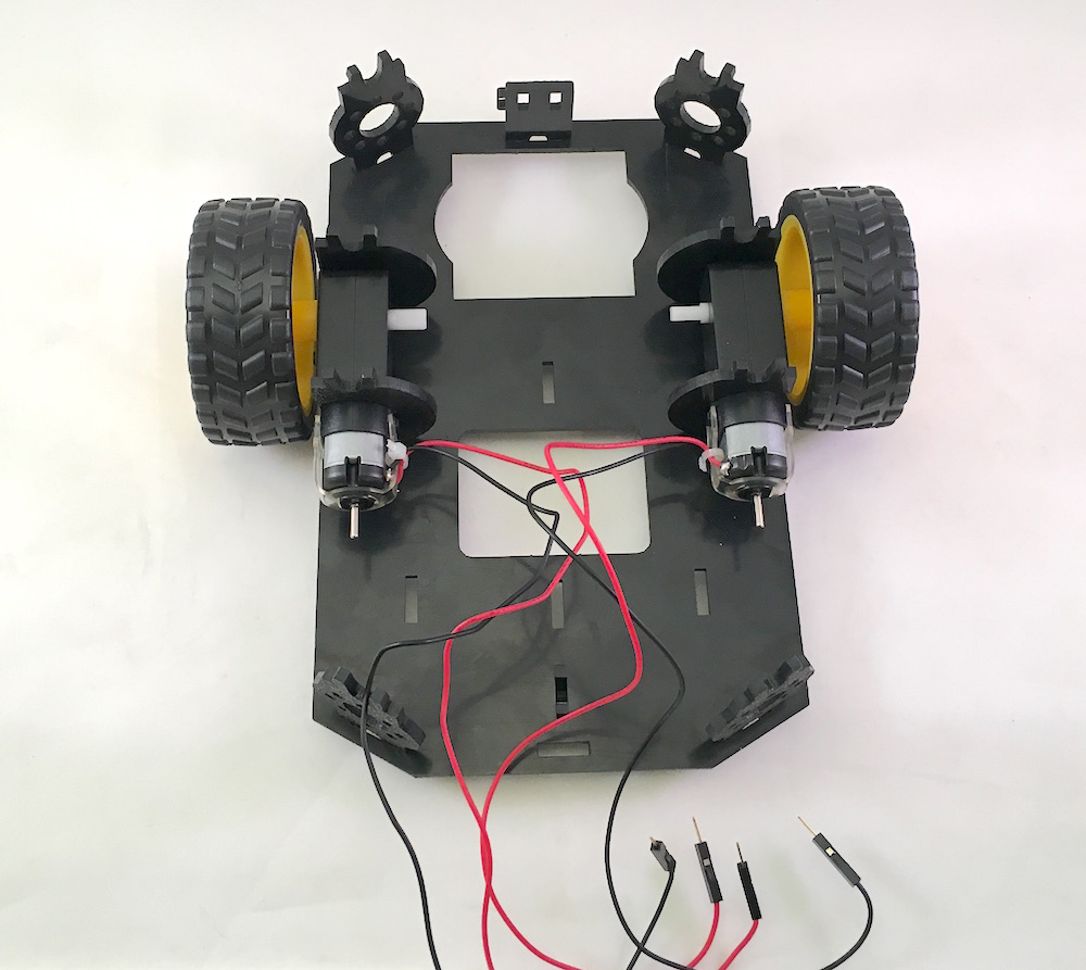
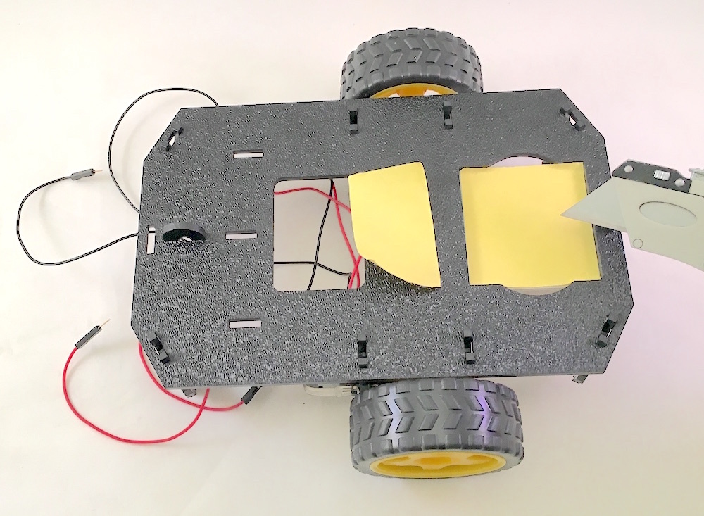
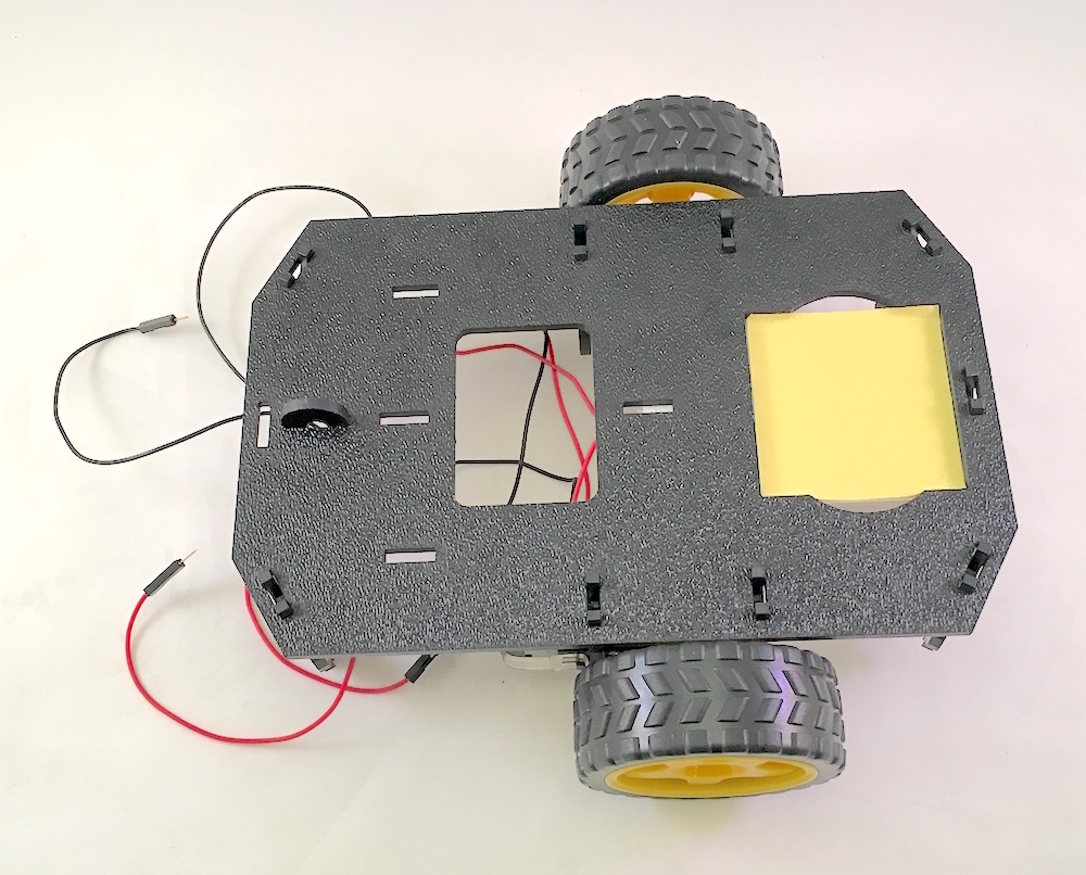
- Flip the base over and attach the little semicircular support nubbin from the Shadow Chassis kit near the back end of the robot (toward bottom left of the following photo)

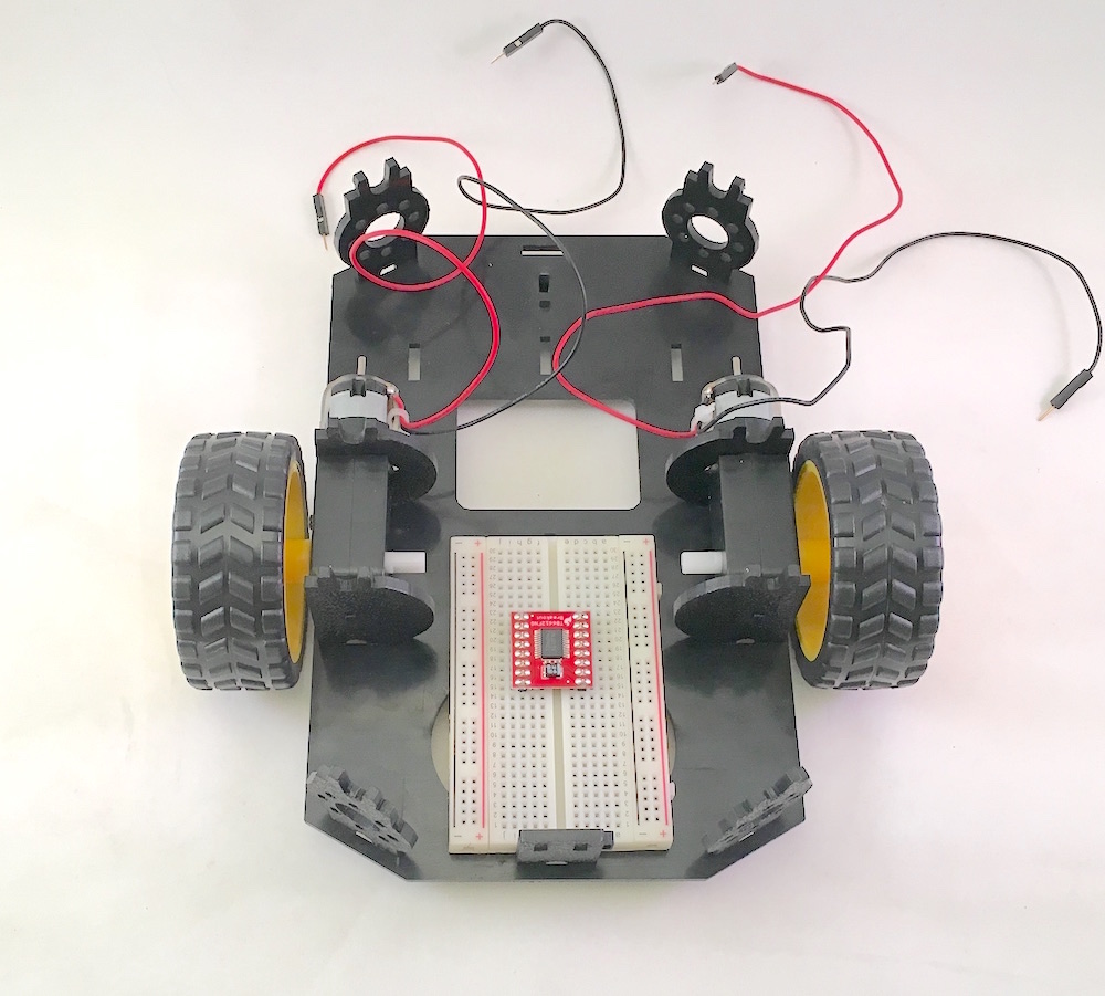
Some more views of the chassis base (this version has black motors):
Attach the Camera
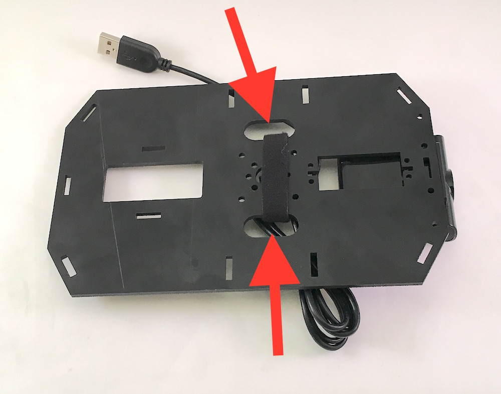
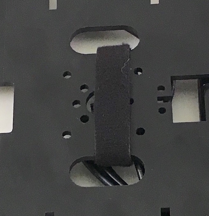
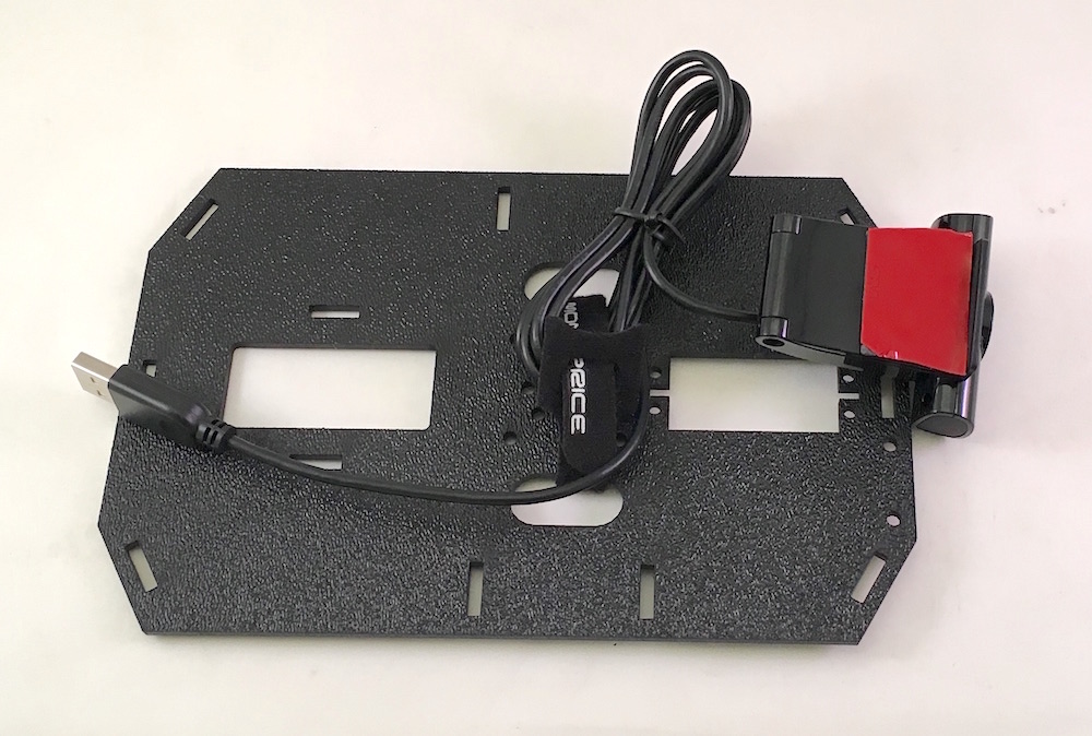
With the top panel in hand—that's the other big piece in the Shadow Chassis kit—loop one of the ~~Hook and Loop Fastening Cable Ties~~ Velcro ties through the two oblong cut-outs positioned between the wheel mounts:
Next, place the top panel (shiny side down) in front of you. Cut a piece of two-sided tape or mounting tape, approximately half the length of the bottom side of the camera clip (or full length, it's up to you) and attach to the camera clip, like so:
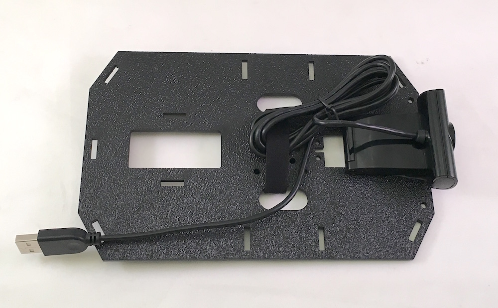
Then flip the camera over and fasten it to the rough side of the top panel. Use the Velcro tie to wrap the camera's USB cable:
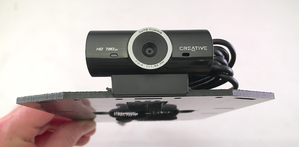
Make sure the front "lip" of the camera clip is flush with the edge of the top panel, and that the camera lens itself is centered:
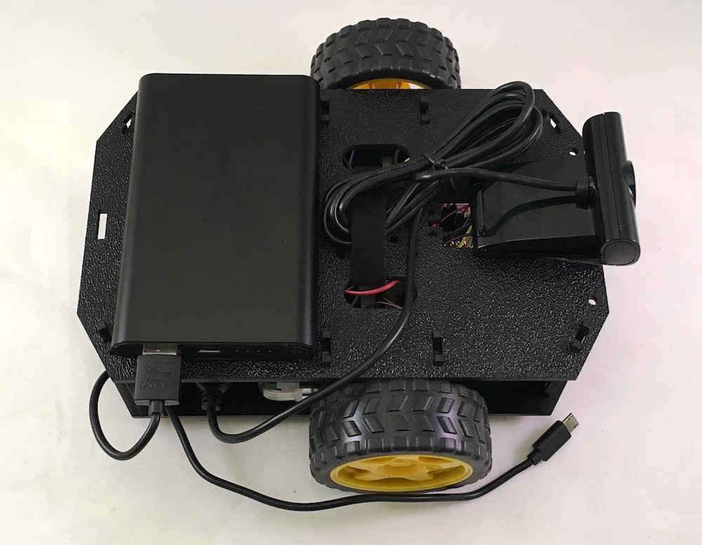
Cut another piece of double sided tape and attach to one side of the USB battery:

Remove the adhesive paper from the other side of the tape, and place the battery on the top panel:
Attach the Breadboard
Now for a shocking twist: set the top assembly aside and grab the bottom assembly and then carefully remove the adhesive strip paper from the breadboard (we're going to reuse it) and place the breadboard over the hole in the front section of the bottom panel. (As it turns out, most people never remove this adhesive cover strip!).
Turn the bottom assembly over and press the paper backing onto the adhesive surface that's exposed through the hole. Turns out they are the same size! Using a sharp utility knife, trim off the excess paper.
Once trimmed, the underside of the chassis base should like this:
Wire the Motor Driver Circuit
Turn the bottom assembly right-side-up and insert the Motor Driver breakout onto the breadboard, as shown here:
Wire in the Motor Driver, by following the diagram here:
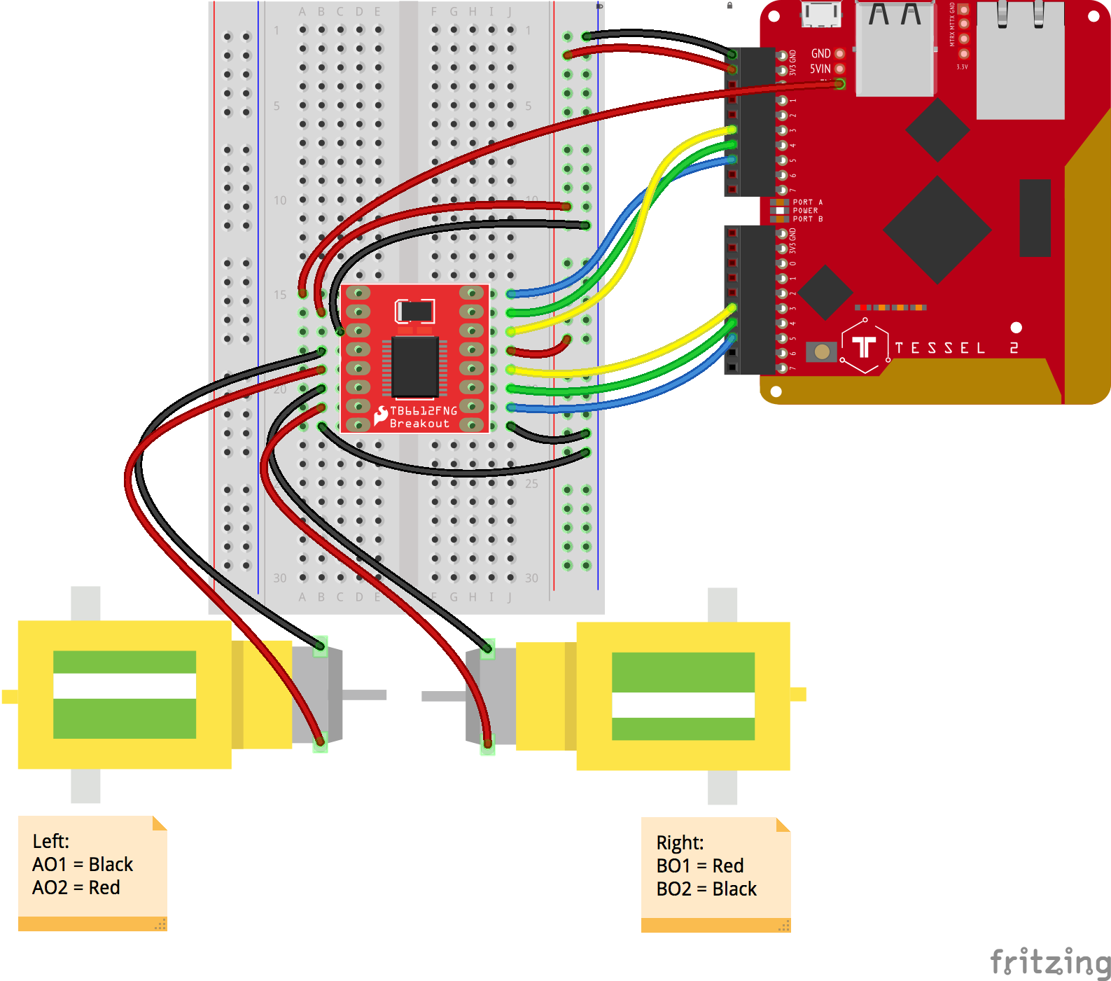
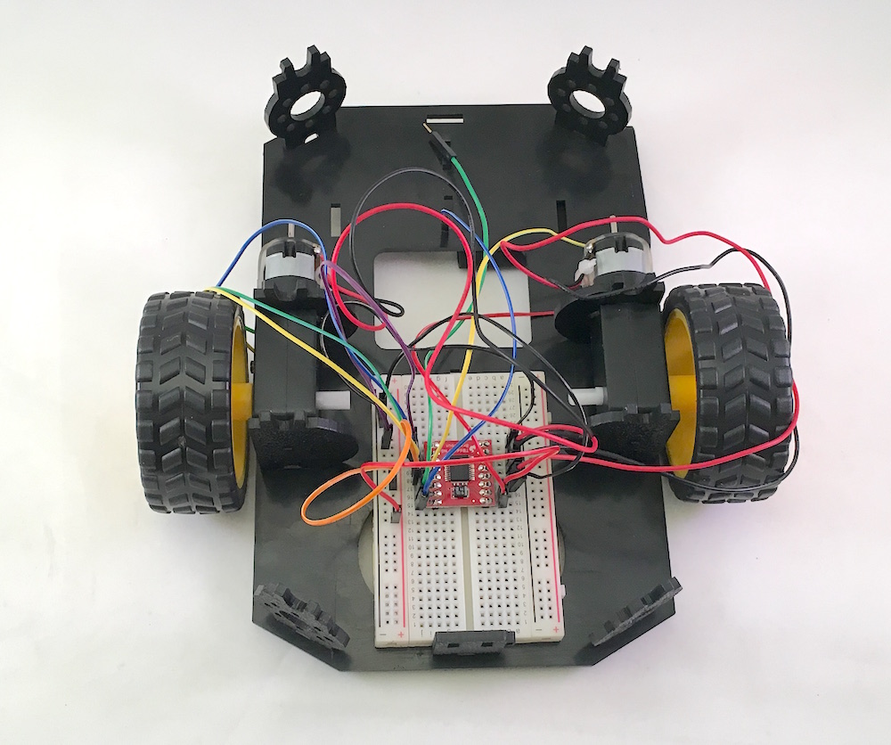
Start by making the breadboard connections (we'll connect to the Tessel 2 in a few moments). As you assemble, your work should look similar to following image:
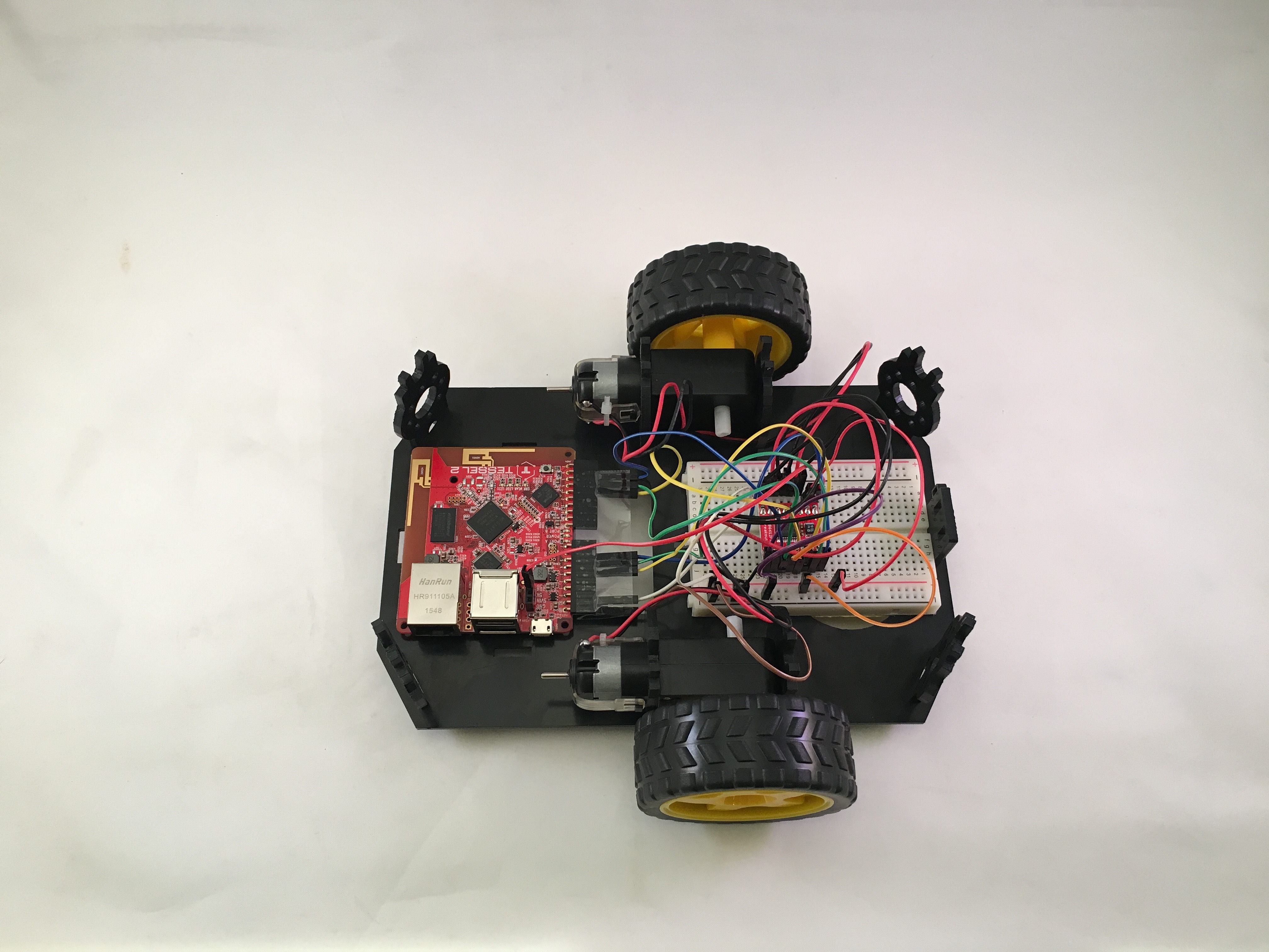
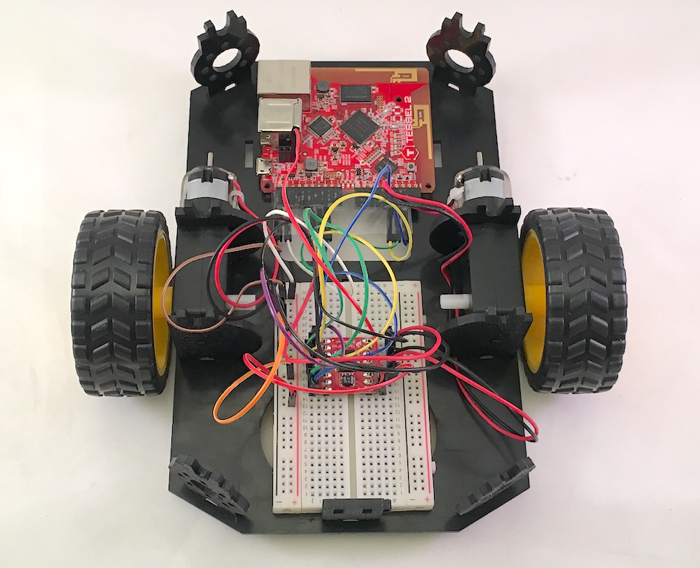
Connecting the Tessel 2
Position the Tessel 2 near the rear of the robot on the bottom panel and complete the connections for the motor driver.
To help you verify your wiring, review the following tables:
| Motor | Wire | Driver Pin |
|---|---|---|
| Left | Black | AO1 |
| Left | Red | AO2 |
| Right | Black | BO2 |
| Right | Red | BO1 |
| Motor | Tessel Pin | Driver Pin | Color In Diagram |
|---|---|---|---|
| Left | Port A, Pin 5 | PWMA | Blue |
| Left | Port A, Pin 4 | AIN2 | Green |
| Left | Port A, Pin 3 | AIN1 | Yellow |
| Right | Port B, Pin 5 | PWMB | Blue |
| Right | Port B, Pin 4 | BIN2 | Green |
| Right | Port B, Pin 3 | BIN1 | Yellow |
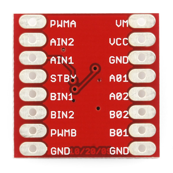
Above: the pins of the SparkFun Motor Driver Breakout board. Note that this view is of the bottom of the board. As attached to your breadboard, connections will be flipped left-to-right.