Qwiic 6DoF (LSM6DSO) Breakout Hookup Guide
Introduction
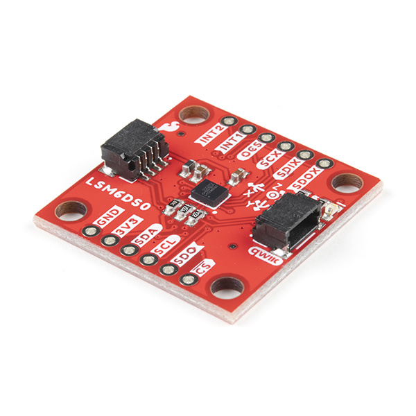
O as opposed to the number 0. There is also the LSM6DS0 that was released by STMicroelectronics but it is EOL.
The LSM6DSO is an accelerometer and gyroscope sensor with a giant 9 kbyte buffer and embedded processing interrupt functions, specifically targeted at the cellphone market. The sensor is super-flexible and can be configured specifically for an application. We've put together a driver and slew of examples to help you explore the possibilities.
Some of the things the LSM6DSO can do:
- Read accelerometer data up to 6.66 kilosamples per second, for super accurate movement sensing
- Read gyroscope data up to 6.66 kilosamples per second
- Operates at 0.55mA for up to 6.66 ksps modes
- Read temperature
- Buffer up to 9 kbytes of data between reads (built-in FIFO)
- Count steps (Pedometer)
- Detect shocks, tilt, motion, taps, double-taps
- Host other sensors into its FIFO
- Drive interrupt pins by embedded functions or by FIFO low-capacity/overflow warning.
Covered In This Tutorial
This tutorial gives you all you need to get going with the LSM6DSO. We'll introduce you to the chip itself, then the breakout board. Then we'll switch over to example code and show you how to interface with the board using an Arduino and our SparkFun LSM6DSO Arduino library.
The tutorial is split into the following pages:
- Introduction - Basic information
- Hardware Overview - Hardware connections
- Hardware Assembly - Connect to the LSM6DSO by I2C or SPI
- Installing the Arduino Library - Includes overview of the examples
- Using the Arduino Library - Explains the user API
- Resources and Going Further - Links to the datasheet and application notes, plus inspirational projects
Required Materials
To follow along with this tutorial, you will need the following materials. You may not need everything though depending on what you have. Add it to your cart, read through the guide, and adjust the cart as necessary.
Qwiic Cable - 100mm
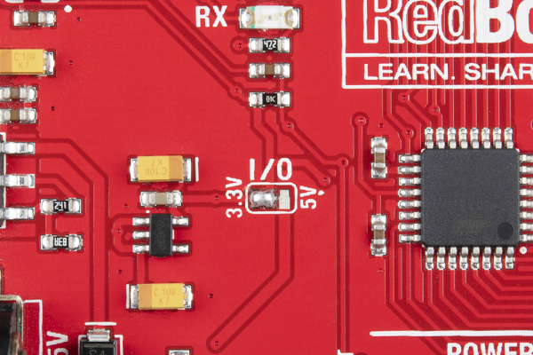
PRT-14427The RedBoard Qwiic has two level shifters on the I2C lines so you do not need to worry about the logic levels when using the board in I2C mode. You could also adjust the system voltage by cutting the jumper and adding solder to the 3.3V side when using the board in SPI.
Suggested Reading
If you aren't familiar with the Qwiic system, we recommend reading here for an overview .
 |
| Qwiic Connect System |
If you aren’t familiar with the following concepts, we also recommend checking out a few of these tutorials before continuing.
