Qwiic 6DoF (LSM6DSO) Breakout Hookup Guide
Introduction
O as opposed to the number 0. There is also the LSM6DS0 that was released by STMicroelectronics but it is EOL.
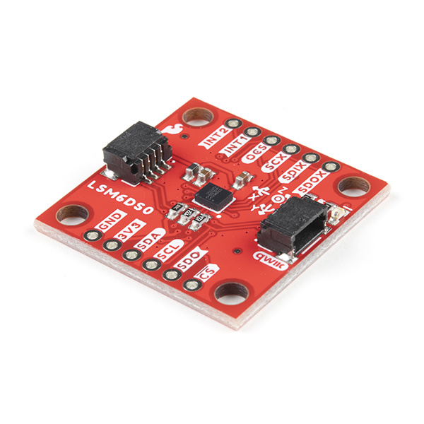
The LSM6DSO is an accelerometer and gyroscope sensor with a giant 9 kbyte buffer and embedded processing interrupt functions, specifically targeted at the cellphone market. The sensor is super-flexible and can be configured specifically for an application. We've put together a driver and slew of examples to help you explore the possibilities.
Some of the things the LSM6DSO can do:
- Read accelerometer data up to 6.66 kilosamples per second, for super accurate movement sensing
- Read gyroscope data up to 6.66 kilosamples per second
- Operates at 0.55mA for up to 6.66 ksps modes
- Read temperature
- Buffer up to 9 kbytes of data between reads (built-in FIFO)
- Count steps (Pedometer)
- Detect shocks, tilt, motion, taps, double-taps
- Host other sensors into its FIFO
- Drive interrupt pins by embedded functions or by FIFO low-capacity/overflow warning.
Covered In This Tutorial
This tutorial gives you all you need to get going with the LSM6DSO. We'll introduce you to the chip itself, then the breakout board. Then we'll switch over to example code and show you how to interface with the board using an Arduino and our SparkFun LSM6DSO Arduino library.
The tutorial is split into the following pages:
- Introduction - Basic information
- Hardware Overview - Hardware connections
- Hardware Assembly - Connect to the LSM6DSO by I2C or SPI
- Installing the Arduino Library - Includes overview of the examples
- Using the Arduino Library - Explains the user API
- Resources and Going Further - Links to the datasheet and application notes, plus inspirational projects
Required Materials
To follow along with this tutorial, you will need the following materials. You may not need everything though depending on what you have. Add it to your cart, read through the guide, and adjust the cart as necessary.
Qwiic Cable - 100mm
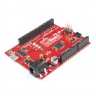
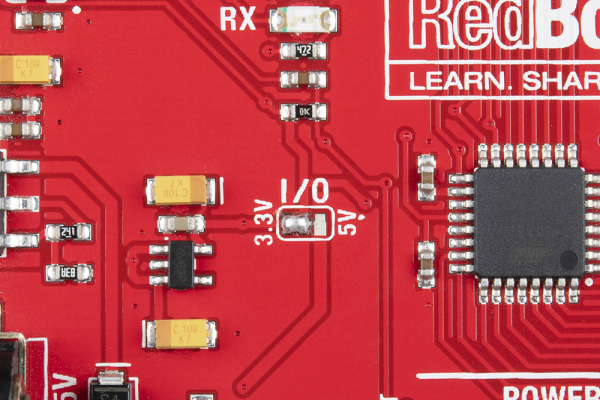
PRT-14427The RedBoard Qwiic has two level shifters on the I2C lines so you do not need to worry about the logic levels when using the board in I2C mode. You could also adjust the system voltage by cutting the jumper and adding solder to the 3.3V side when using the board in SPI.
Suggested Reading
If you aren't familiar with the Qwiic system, we recommend reading here for an overview .
 |
| Qwiic Connect System |
If you aren’t familiar with the following concepts, we also recommend checking out a few of these tutorials before continuing.
Serial Peripheral Interface (SPI)
Gyroscope
Logic Levels
Accelerometer Basics
I2C
Hardware Overview
In this section, we'll highlight the features of the board. We recommend looking at the datasheet and application notes linked in the Resources and Going Further for more information on the LSM6DSO. Open them in a non-browser viewer that can display the index/table of contents in a pane. There is so much information, paned viewing is a must!
Power and Logic Levels
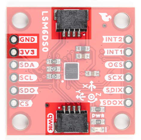
We recommend powering the board through the Qwiic connector when quickly prototyping. For a more secure connection, you can always solder to the PTH labeled 3V3 and GND. The recommended input voltage when using the board with a microcontroller is 3.3V if you are using the Qwiic connector. However, you can use a regulated supply voltage between 1.71V and 3.6V to power the sensor. The logic levels will match the input voltage (e.g. if the sensor is powered at 3.3V, the logic level will be 3.3V as well).
I2C
The main method of reading the LSM6DSO is through the I2C bus. The board includes two Qwiic connectors for fast prototyping and removes the need for soldering. All you need to do is plug a Qwiic cable into the Qwiic connector and voila! You can also solder to the PTHs labeled as SDA and SCL as an alternative. The default address for the IC is 0x6B. However, you can adjust the jumper on the back of the board to change the address to 0x6A.
SPI
If you decide to use a SPI bus, you will need to solder header pins or wires to the board.
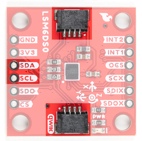
- SDA/SDI - Device data in. Note that the SDA pin used for I2C is also the SDI pin used for SPI. Flipping the board to the bottom side will show the label for the SPI pin.
- SCL - Serial clock for either I2C or SPI.
- SDO - Device data out. By default, the SDO pin is connected to power to set the I2C address. Make sure to cut the trace as explained below if you decide to use this sensor in SPI mode.
- CS - Chip select.
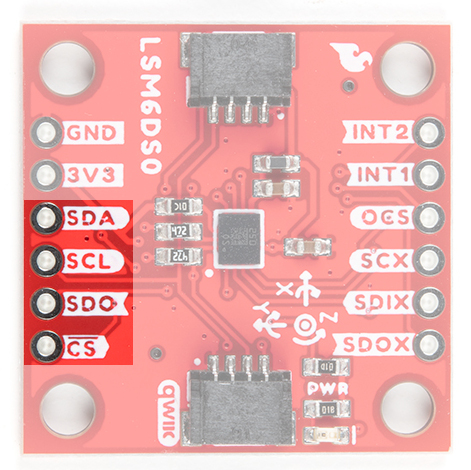 |
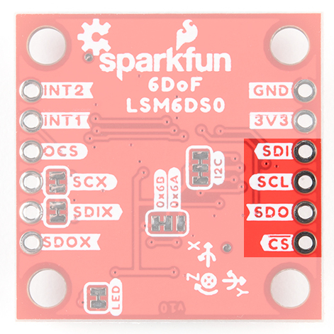 |
| Top of Board for SPI | Bottom of Board for SPI |
When using the board in SPI mode, you will need to cut the I2C jumper for the default address (e.g. 0x6B) on the back and leave the jumper pads unconnected when using SPI.
Interrupt Pins
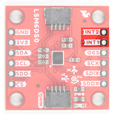
INT1 and INT2 are programmable interrupts for the accelerometer and gyroscope. They can be set to alert on over/under thresholds, data ready, or FIFO overruns. Make sure these are connected to an INPUT pin to prevent driving 5v back into the LSM6DSO.
There are a variety of interrupts on the LSM6DSO. While connecting these is not as critical as the communication or power supply pins, using them will help you get the most out of the chip.
The interrupt pins are INT1 and INT2. One or both pins can be software configured and mapped to the following conditions:
- Step detected
- Step detected after delta time
- Step counter overflowed
- Significant motion (shock, drop)
- FIFO full
- FIFO overrun
- FIFO threshold reached (Datasheet calls this the "watermark")
- Boot status
- Gyroscope data ready
- Accelerometer data ready
- Inactivity
- Single tap
- Wake-up
- Free-fall
- Double tap
- 6D (orientation)
- Tilt
- Timer
- Ironing interrupt
Only a few interrupt examples are provided. See the datasheet and application guide for using the advanced interrupt features.
Auxiliary Pins
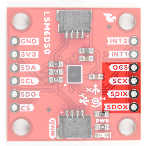
The auxiliary serial data output pins are used to attach slave I2C and auxiliary SPI 3/4-wire devices for FIFO data collection. This function is not covered in this tutorial.
- OCS - aux chip select
- SCX - aux serial clock
- SDIX - aux serial data input
- SDOX - aux serial data output
Reference Axis
For easy reference, we've documented the 6DoF's vectors with 3D Cartesian coordinate axes on the top and bottom side of the board. Make sure to orient and mount the board correctly for your application. Remember, it's all relative.
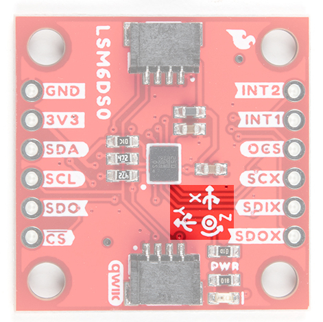 |
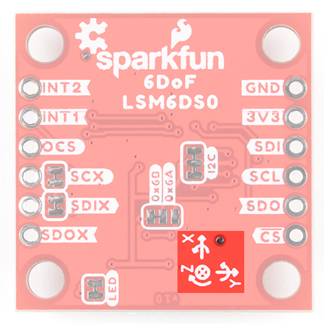 |
| 6DoF Reference (Top) | 6DoF Reference (Bottom) |
LED
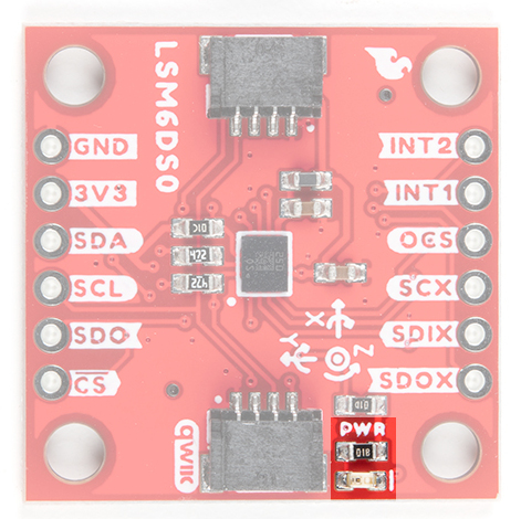
The board includes an LED indicator that lights up when there is power available.
Jumper Pins
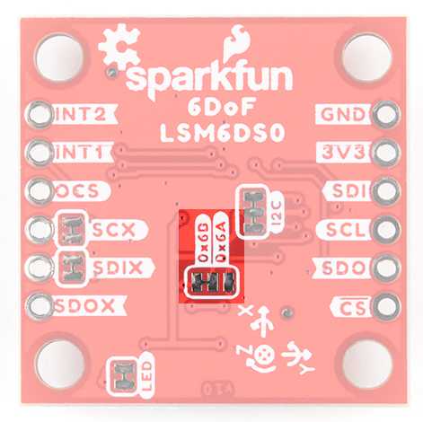
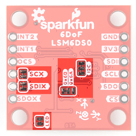
There are five jumpers on the back of the board. For more information, check out our tutorial on working with jumper pads and PCB traces should you decide to cut the traces with a hobby knife.
- LED - This is connected to the PWR LED on the top of the board. Cutting this disables the LED.
- I2C - The I2C jumper is connected to the 4.7kΩ pull-up resistors for the I2C bus. Most of the time you can leave these alone unless your project requires you to disconnect the pull-up resistors. SPI works with these connected but really should be cut apart for better signal shape at high speeds and to lower power consumption.
- 0x6B/0x6A - These jumpers are used to select the address 0x6B (default) or 0x6A for I2C communication. This jumper must be opened for SPI mode or the SDO line will not supply data.
- SCX - By default, this pin is connected to GND since ST recommends pulling the unused SCX to power or ground when not in use. For most users, you can leave this jumper alone. If your project requires connecting slave devices to the auxiliary pin, cut this trace.
- SDIX - By default, this pin is connected to GND since ST recommends pulling the unused SDIX to power or ground when not in use. For most users, you can leave this jumper alone. If your project requires connecting slave devices to the auxiliary pin, cut this trace.
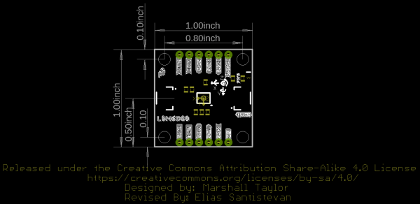
Board Dimensions
The board uses the standard Qwiic size 1.0"x1.0" with four mounting holes by each corner.
Hardware Assembly
I2C Mode
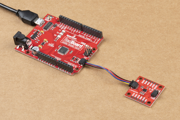
For this example, we'll use a RedBoard Qwiic and associated USB cable. With that and a Qwiic cable, the assembly is very simple. Plug a Qwiic cable between the RedBoard Qwiic and the Qwiic 6DoF LSM6DSO. If you're going to be soldering to the through hole pins, then just attach lines to power, ground, and the I2C data lines to the microcontroller of your choice. Just make sure to match to use a logic level converter to match the 3.3V logic on the Qwiic 6DoF.
SPI Mode
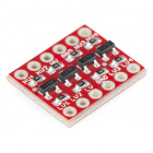
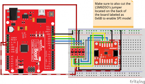
Here's how to connect the SPI lines to a 5V system like the RedBoard Qwiic using a SparkFun Logic Level Converter. Be sure to orient the converter's low side to the LSM6DSO. If using a Teensy or other 3.3V microcontroller, the SPI lines can be connected directly!
Installing the Arduino Library
We've written an Arduino library to help make interfacing with the LSM6DSO's gyro, accelerometer, and temperature sensor as easy-as-possible. Download using the Arduino library manager by searching for 'SparkFun Qwiic 6DoF LSM6DSO Arduino Library' or you can manually install the library by downloading the zip here from the GitHub repository:
Examples
Basic Readings
There are a few examples in the library but we recommend using the Basic Readings in I2C mode to get started.
Hook up the LSM6DSO to the I2C bus, and click "File > Examples > SparkFun Qwiic 6 DoF - LSM6DSO > Basic_Readings". This example demonstrates the highest level of usage. Besides setting up the Wire library and bus, you will you have to do is create a variable of the type "LSM6DSO", set it to .begin();, and initialize the BASIC_SETTINGS. To read the accelerometer, gyro, or temperature sensor using the Arduino Serial Monitor.
We'll assume that you have selected the board (in this case the Arduino Uno), COM port at this point. If you have the code open, hit the upload button. Otherwise, copy and paste the following into the Arduino IDE.
language:c
/******************************************************************************
Basic_Readings.ino

https://github.com/sparkfun/SparkFun_Qwiic_6DoF_LSM6DSO
https://github.com/sparkfun/SparkFun_Qwiic_6DoF_LSM6DSO_Arduino_Library

Description:
Most basic example of use.

Example using the LSM6DSO with basic settings.  This sketch collects Gyro and
Accelerometer data every second, then presents it on the serial monitor.

Development environment tested:
Arduino IDE 1.8.2

This code is released under the [MIT License](http://opensource.org/licenses/MIT).
Please review the LICENSE.md file included with this example. If you have any questions
or concerns with licensing, please contact techsupport@sparkfun.com.
Distributed as-is; no warranty is given.
******************************************************************************/

#include "SparkFunLSM6DSO.h"
#include "Wire.h"
//#include "SPI.h"

LSM6DSO myIMU; //Default constructor is I2C, addr 0x6B

void setup() {


  Serial.begin(115200);
  delay(500);

  Wire.begin();
  delay(10);
  if( myIMU.begin() )
    Serial.println("Ready.");
  else {
    Serial.println("Could not connect to IMU.");
    Serial.println("Freezing");
  }

  if( myIMU.initialize(BASIC_SETTINGS) )
    Serial.println("Loaded Settings.");

}


void loop()
{
  //Get all parameters
  Serial.print("\nAccelerometer:\n");
  Serial.print(" X = ");
  Serial.println(myIMU.readFloatAccelX(), 3);
  Serial.print(" Y = ");
  Serial.println(myIMU.readFloatAccelY(), 3);
  Serial.print(" Z = ");
  Serial.println(myIMU.readFloatAccelZ(), 3);

  Serial.print("\nGyroscope:\n");
  Serial.print(" X = ");
  Serial.println(myIMU.readFloatGyroX(), 3);
  Serial.print(" Y = ");
  Serial.println(myIMU.readFloatGyroY(), 3);
  Serial.print(" Z = ");
  Serial.println(myIMU.readFloatGyroZ(), 3);

  Serial.print("\nThermometer:\n");
  Serial.print(" Degrees F = ");
  Serial.println(myIMU.readTempF(), 3);

  delay(1000);
}
After uploading, open the Serial Monitor and set it at 115200.
Resources and Going Further
There are a gazillion ways to use an IMU, from simple gravity sensing to advanced motion tracking. There are so many ways to configure the LSM6DSO! After you've used your Arduino and the examples to get the hang of things, use this process:
- Read the datasheet and application note!
- Design an experiment to try an idea
- Measure the results
Only this, is the way to improve.
- Schematic (PDF)
- Eagle Files (ZIP)
- Board Dimensions (PNG)
- Datasheet (PDF) - This datasheet covers everything from the hardware and pinout of the IC, to the register mapping of the gyroscope and accelerometer.
- Application Notes (PDF) - This application note has the same information as the datasheet, but puts real English words in there to try and help out the humans. Use both this and the datasheet together in a tabbed PDF viewer, with the index window open, for maximum efficiency.
- Arduino Library
- GitHub Hardware Repo
Need a little inspiration? Check out some of these tutorials!
