Photon Remote Water Level Sensor
Build the Remote Telemetry Box
Energy Considerations -- Battery and Solar Cell Sizing
The plan is to periodically wake up the Photon to take a measurement, then put it into deep sleep if the battery level is not very full. The Photon energy use specs are here. The maximum average WiFi operating current is 100mA, and the maximum deep sleep operating current is 0.1mA. Assuming an on time of 60 seconds and an off time of 5 minutes, we use about 400mAh per day. If we want to have the Photon last for three days without any sunlight (sometimes it can blizzard here for a day or two), we need at least 1200mAh of battery capacity. The nearest battery size available from SparkFun, rounding up, is 2000mAh. However, you can play with the sleep cycle time by copying this spreadsheet and get down to a pretty small battery size. Also, by sleeping the Photon longer at night when there's less water usage, we can extend the battery life dramatically.
| Pin Label | Pin Description |
|---|---|
| 1 | Switch contact 1 |
| 2 | Switch contact 2 |
| + | LED anode |
| - | LED cathode |
A Watt = V * A, so our 3.5W solar cell providing power at 5V is pushing 0.7A. We should be able to charge our 2000mAh battery pretty quickly (about 3h) under ideal conditions. However, the cell will get dusty, days will be cloudy, etc, so it's best to oversize when in doubt. If you want to save some bucks, the 2W solar cell should push about 0.4A under ideal conditions.
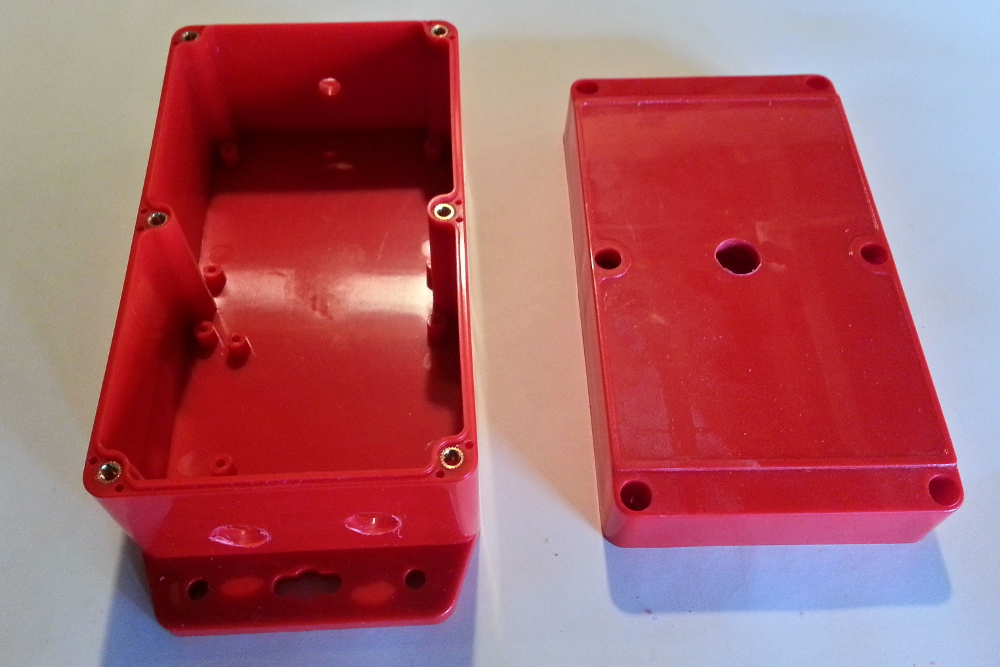
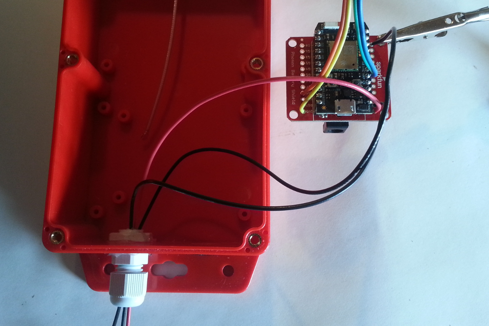
Physical Construction
Drill ½" holes for the cable gland and pressure/humidity hole on the side of the box you expect to get the least rainfall/water exposure, and a ¼" hole for the antenna on the same side. Drill another ½" hole in the lid of the box for the photocell window. I accidentally installed the antenna on the top of the box, where rain will hit it directly. If you want to mount the battery shield with 6-32 screws, drill some 1/8" holes as well on the bottom of the box. Put silicone around the photocell hole on the cover and press the glass on the outside of the hole. Put silicone around the cable gland hole and the antenna hole, and install both of them.
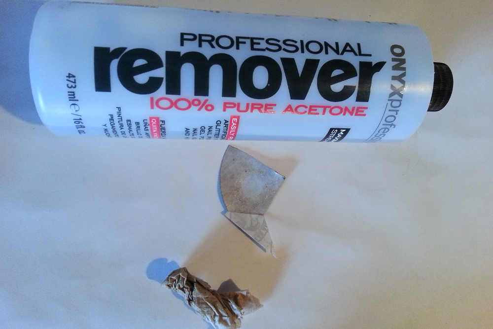
Waterproof Holes
We need a hole to let humidity, pressure, and temperature equilibrate with our BME280 sensor, but we don't want to let rain water in. The solution I came up with is to use a GoreTex repair patch pad and to use a solvent to get rid of the adhesive on the area that lets humidity through. Most solvents you've got laying around should be fine (acetone, mineral spirits, goof-off, ethanol--such as Everclear), but check with this chart before trying any solvents not mentioned here. Take a rag, paper towel or napkin, douse it with some acetone, and rub off the adhesive on the back of the repair patch. This will dissolve the adhesive after a bit of work. When you can touch the spot you've treated and don't feel the sticky adhesive, you're probably good. I'm not sure if the adhesive lets moisture and pressure through very well or not, as I haven't tested, but, once the adhesive is removed, it works well.
Put a bit of silicone around the hole just to make sure it gets sealed well, and apply the patch.
Electrical Hookup
Battery Shield
Solder the four legs of the SMD barrel jack plug to the board, as described here.
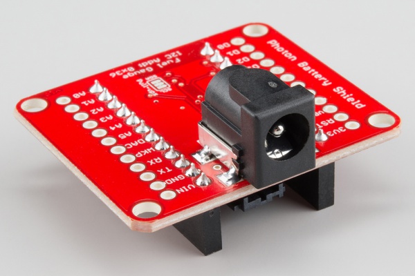
You can test it with the MAX17043 library. Details on using the battery shield are beyond the scope of this project tutorial, as that information can be found in the Battery Shield Hookup Guide.
BME 280 Pressure, Humidity, Temperature
The BME280 can read pressure, humidity, and temperature, so it makes a nice mini weather station. Changes in air pressure are an easy way to predict incoming storms (unless you're in a more tropical climate, like the gulf coast). We can use some guidelines to classify pressure changes on the hour timescale, and we'll post that information to a Twitter account. Basically, if pressure is dropping, the rate of the drop indicates how soon a storm is likely on the way. Dropping air pressure usually also means rising wind speeds; rising pressure usually means good weather.
Here's a table of pressure drop over three hours that we're going to use to classify our data, referenced from here:
| Classification | min pressure rate (inHg/min * 10^6) | max pressure (inHg/min *10^6) | lower limit % change over 3 hours |
|---|---|---|---|
| Steady | 0 | 16 | 0 |
| Changing slowly | 16 | 246 | 0.01 |
| Changing moderately | 246 | 574 | 0.15 |
| Changing rapidly | 574 | 984 | 0.35 |
| Changing very rapidly | 984 | 0.59 |
Essentially, if we have a 0.6% change in pressure in three hours, the pressure is changing very rapidly and bad weather may be on the way. We'll post to a Twitter account and set up text alerts for when pressure is dropping very rapidly. The spreadsheet for the calculations is here, in case you want copy it and mess with it.
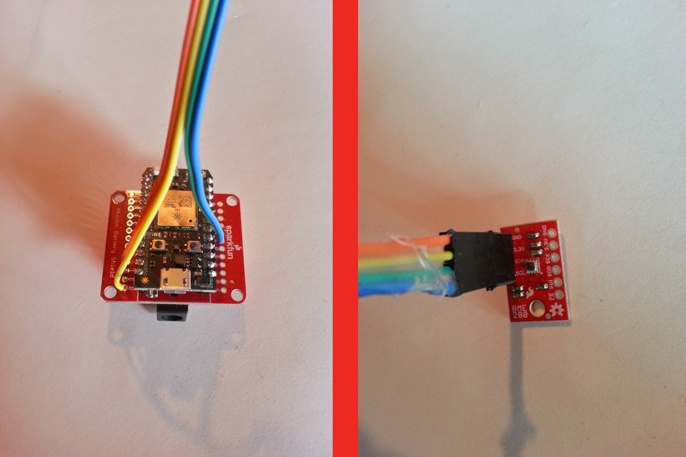
Solder some M-M jumpers to the BME280 board, and solder the other ends to GND, 3.3V, and D0/D1 (SDA/SCL) pins on the battery shield, respectively.

Start a new Photon project on www.build.particle.io, include the library "SPARKFUNBME280" (click the 'Libraries' icon on the left, search in the box for BME280, click the SPARKFUNBME280 library, click 'Include in App', click the name of your app, click 'Add to App') and upload this code to your photon to test the sensor:
language:c
/******************************************************************************
I2C_and_SPI_Multisensor.ino
BME280 Particle Photon example

Sensor A is I2C and connected through D0/D1 (SDA/SCL)
******************************************************************************/

#include "SparkFunBME280/SparkFunBME280.h"

BME280 mySensorA;

void setup()
{
    // set up sensor
    mySensorA.settings.commInterface = I2C_MODE;
    mySensorA.settings.I2CAddress = 0x77;
    mySensorA.settings.runMode = 3; //  3, Normal mode
    mySensorA.settings.tStandby = 0; //  0, 0.5ms
    mySensorA.settings.filter = 0; //  0, filter off
    //tempOverSample can be:
    //  0, skipped
    //  1 through 5, oversampling *1, *2, *4, *8, *16 respectively
    mySensorA.settings.tempOverSample = 1;
    //pressOverSample can be:
    //  0, skipped
    //  1 through 5, oversampling *1, *2, *4, *8, *16 respectively
    mySensorA.settings.pressOverSample = 1;
    //humidOverSample can be:
    //  0, skipped
    //  1 through 5, oversampling *1, *2, *4, *8, *16 respectively
    mySensorA.settings.humidOverSample = 1;


    delay(6000); // so you have time to start the serial monitor and see the initial output
    Serial.print("Program Started\n");
    Serial.println("Starting BME280s... result of .begin():");
    delay(10);  //Make sure sensor had enough time to turn on. BME280 requires 2ms to start up.
    //Calling .begin() causes the settings to be loaded
    Serial.print("Sensor A: 0x");
    Serial.println(mySensorA.begin(), HEX);
}

void loop()
{
    //Start with temperature, as that data is needed for accurate compensation.
    //Reading the temperature updates the compensators of the other functions
    //in the background.
    Serial.print("Tempferature: ");
    Serial.print(mySensorA.readTempC(), 2);
    Serial.println(" degrees C");

    Serial.print("Temperature: ");
    Serial.print(mySensorA.readTempF(), 2);
    Serial.println(" degrees F");

    Serial.print("Pressure: ");
    Serial.print(mySensorA.readFloatPressure(), 2);
    Serial.println(" Pa");

    Serial.print("Pressure: ");
    Serial.print(mySensorA.readFloatPressure()*29.529983/100000, 2);
    Serial.println(" inHg");

    Serial.print("Altitude: ");
    Serial.print(mySensorA.readFloatAltitudeMeters(), 2);
    Serial.println("m");

    Serial.print("Altitude: ");
    Serial.print(mySensorA.readFloatAltitudeFeet(), 2);
    Serial.println("ft");

    Serial.print("%RH: ");
    Serial.print(mySensorA.readFloatHumidity(), 2);
    Serial.println(" %");

    Serial.println();

    delay(2000);

}
Type 'particle serial monitor' in your command prompt/terminal, and check to make sure the output is reasonable and working.
CdS Photocell
To measure light levels, we'll use a CdS photocell. We're going to use a 1 k resistor as a pull-down. Information on how to use a photocell can be found here. Solder the connections as so:

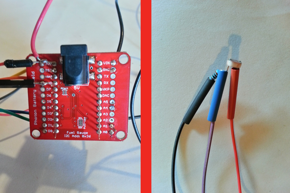
It ended up being tough for me to place the CdS cell in the glass window because my wires were too short, so leave yourself some extra room with at least eight inches of wiring between the battery shield and the CdS cell.
Test the reading of the photocell with a flashlight, using this code:
language:c
void setup() {
    pinMode(A1, INPUT);
}

void loop() {
    float lightIntensity = analogRead(A1);
    Serial.println(lightIntensity);
    delay(1000);
}
Check the serial output with 'particle serial monitor', and make sure the number goes up when you shine a bright light on it. The number should read in the thousands; the range of the Photon analog signal is from 0 to 4095, so make sure the reading isn't near 4095 unless you're in broad daylight or close to a bright LED. There's a nice classification of voltage output levels for different lighting conditions here.
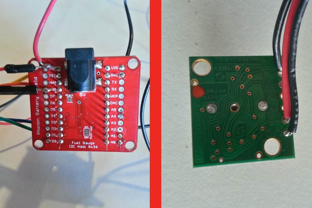
Sensing Distance (Water Height) with an Ultrasonic Sensor
Because air and water have different densities, the water reflects some of the ultrasonic waves sent at it, for example, by something like the MaxSonar-EZ3 sensor (manufacturer's page here). Again, I recommend the waterproof version for reliability.
To add this part to the telemetry box, first measure the distance from where you will put the telemetry box to where the ultrasonic sensor will go, and cut three sufficient lengths of wire. I used 22 AWG hookup wire and ended up with about 8 to 10 ft of wire. Solder the wires to the GND, +5, and PW holes on the device, by soldering the ends of the wires. Pass the wires through the cable gland, and solder the other ends of the wires to the battery shield: GND, 3.3V (or Vin), and A0.

Test the device by uploading this code to your Photon:
language:c
float uSperInch = 147; // from datasheet
float distance;
unsigned long duration;

void setup() {
    pinMode(A0, INPUT);
}

void loop() {
    duration = pulseIn(A0, HIGH);
    Serial.print("pulse length: ");
    Serial.println(duration);
    distance = duration / uSperInch;
    Serial.print(distance);
    Serial.println(" in");
    delay(1000);
}
The datasheet from the manufacturer's page says the pulse width is 147uS/inch, and it seemed to be right around there for me. Double check the readings with a measuring tape though.
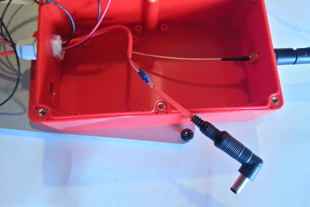
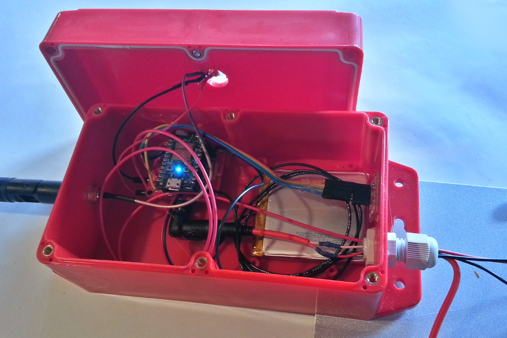
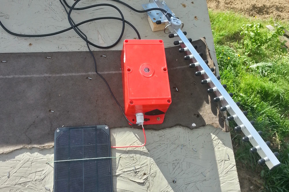
Finishing the Telemetry Box
The few last things to do are pass through the solar cell barrel jack, stuff everything in the box (maybe with a little hot glue), and make sure all the external holes look well sealed up.
We have to cut the solar cell wire in two, and, using your wire strippers, strip each wire down. Then pass the wires through the cable gland and solder them back together. I used heat shrink to make the connections clean. The solar cell cable length is very short, so you might want to add some extensions. You could also add enough of an extension so that the box is in the shade (so it doesn't get too hot, especially if you're in the desert).
Finally, connect the battery and the solar cell to the Battery Shield, and put everything in the box as best you can. I hot-glued most things down, but in the sun, things get pretty hot (as we'll see from the measurements), so the glue tends to un-stick. I did hot-glue the CdS cell to the glass window, and even after it un-stuck (and I reopened the box), it was still pretty easy to put back in the window due to the shape of the glue. Lastly, tighten the six screws down on the top of the box, tighten the cable gland, and maybe put some silicone on the cable gland to make sure it's good and waterproof.
Field Installation
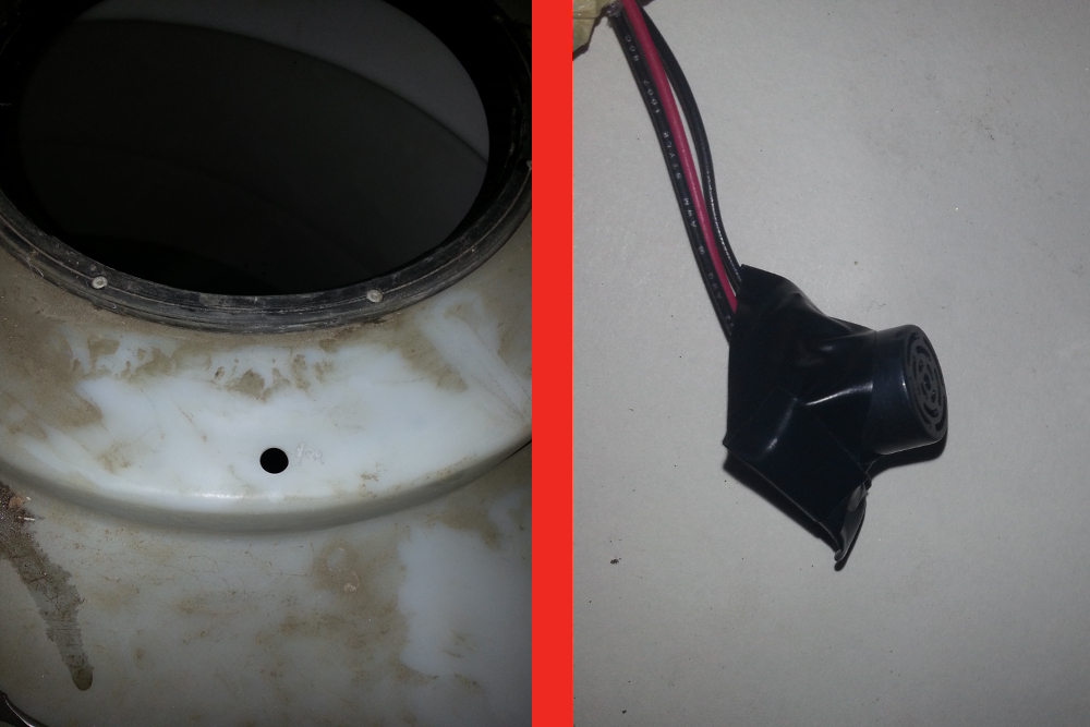
Put the box and solar cell in a place that's going to get some sun. String the wires from the box through to the water tank. This is where things get tricky. If you have giant plastic water tanks, like we do, you'll likely get static electricity buildup that will interfere with the measurements. As long as the sensor isn't touching the tank (I also covered the sensor in aluminum foil and grounded it with a ground rod), it should be ok. If the tank isn't plastic, you can drill a 5/8" hole somewhere in the tank. I covered most of the ultrasonic sensor with black electrical tape as a bit of protection.
If your tank is outside, you will probably be getting condensation at times. The waterproof sensor may fix this problem, otherwise, mount the non-waterproof sensor above the tank (with a hole to let the ultrasound pass into the tank) so that condensation won't be happening on the sensor.
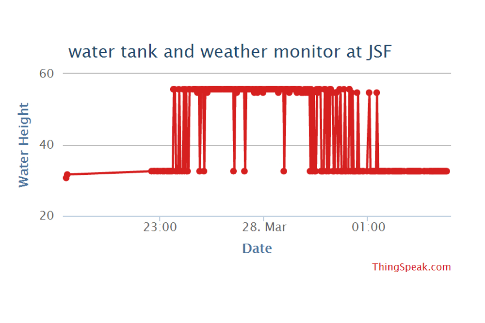
The water tanks on the property where this was installed are gigantic plastic (polyethylene, probably) tanks. The pump is about a half mile away, and the whole distance is bridged by PVC pipe. Possibly due to this, there seems to some static buildup in the system. As evidence, I've felt a massive static field (6-12 inches above the tank) before while climbing on top of the tanks. This appeared to be effecting the ultrasonic sensor, as it would perform great in lab tests, but out in the field it would get wonky after a few measurements (reading values smaller than the minimum distance), and correct measurements would come and go during the day and night. Things seemed to go haywire after the water started flowing for an hour or two--in either direction, in or out.
The other strange thing about this whole deal is when I would plug the photon into my computer, the readings would be OK again, and when I unplugged it, they would go back to being very small and incorrect.
To combat this, I drove a 10ft 1/2" EMT conduit rod about nine feet into the ground with a sledge hammer. I took a wire and connected one end to the EMT conduit. On the other end, I tied a stainless steel bolt to it and dropped it in the water tank. I also tied a wire around the ultrasonic sensor's plastic housing and connected it to the EMT rod. It seemed to help somewhat, but still didn't completely fix the problem.

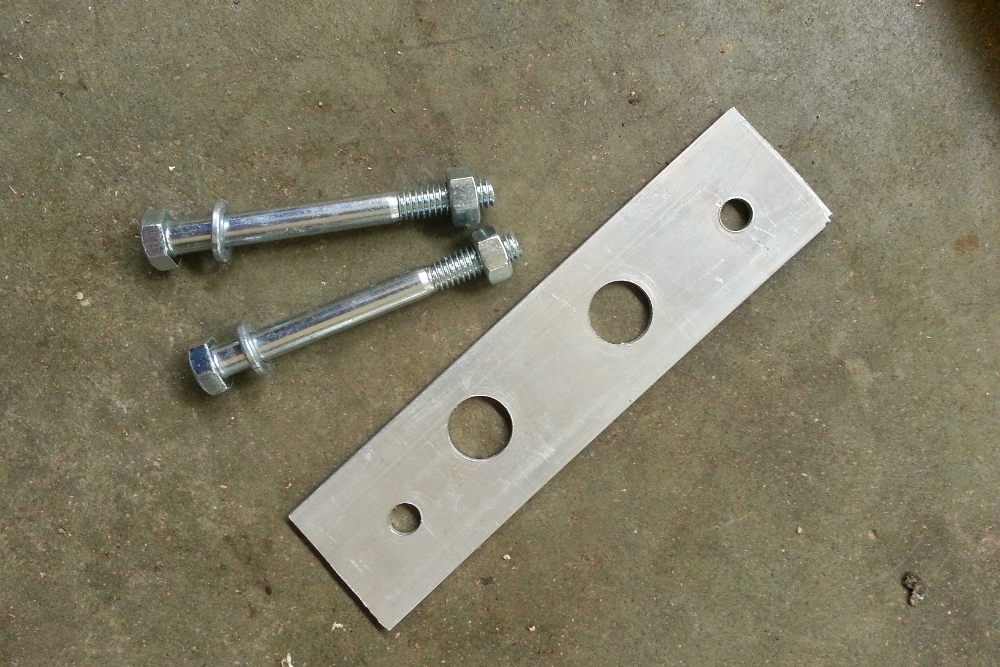
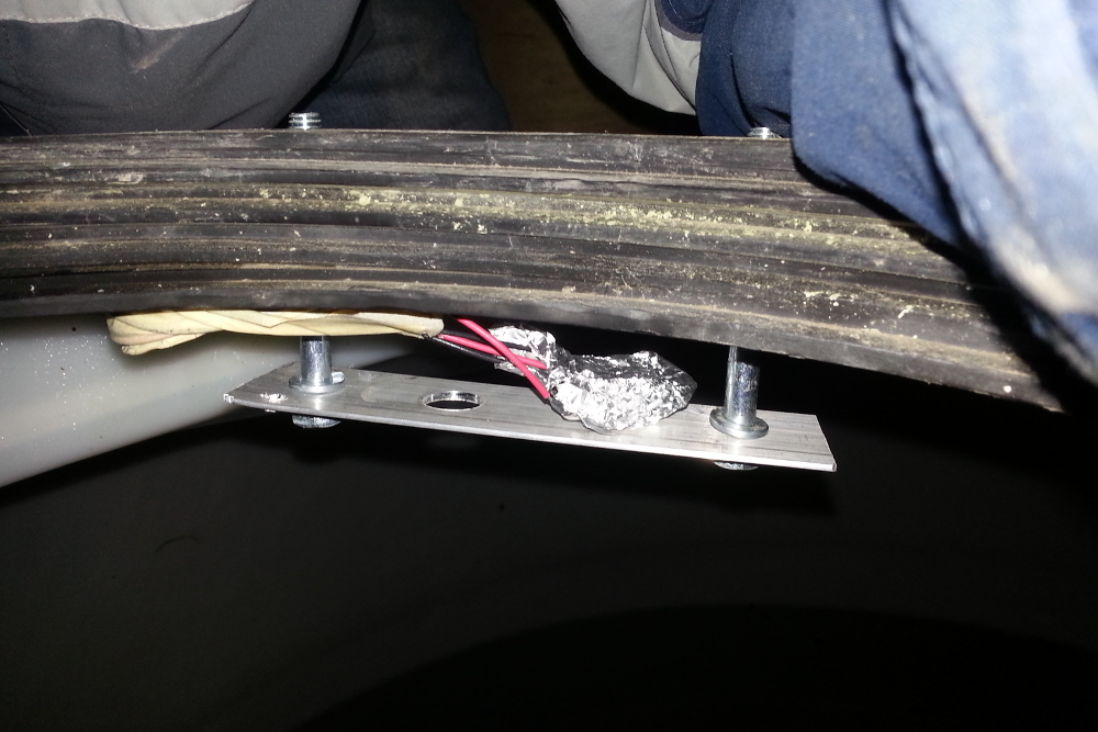
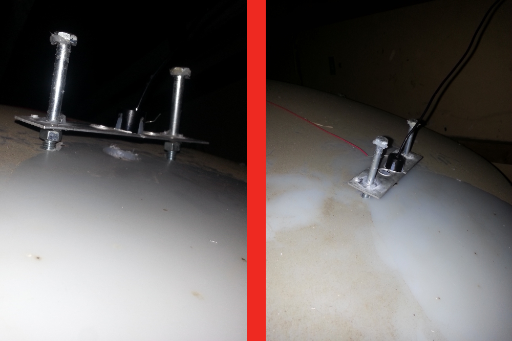
The only way I was able to get the sensor to reliably read water height was to suspend it above the tank, without the plastic housing touching the water tanks. I wrapped the sensor in aluminum foil (except the front face) and attached the ground wire to the foil. I then drilled some holes in a 1.5" aluminum flat bar, attached the bar to the water tank, and attached a grounding wire to the bar. After that, the readings were stable.
However, after a few days, the readings started going haywire. I found there was condensation on the sensor that caused this. If your water tank is outside, mount the sensor above the tank (using something like the metal plate I used), and put a hole in the tank (larger than the sensor diameter), directly below the sensor.
Some people claim plastic can't be grounded, and they may be right. However, adding a grounding lug at the inlet to the tank may work, although I haven't tried this.
Using the waterproof HRXL sensor may completely bypass the static electricity problem; I'm not sure. In any case, it would be a better idea for long-term robustness to use the waterproof sensor.
Finally, you need to know the distance from the bottom of the tank to the front of the sensor, so get out your measuring tape and check that now, and make a note of it. To get the water height, we simply take the total water tank height and subtract the distance read from the ultrasonic sensor.