Photon Remote Water Level Sensor
Introduction
With the advent of cheap Microcontrollers (MCUs), and especially WiFi-MCUs of late, custom DIY automation of many monotonous tasks and telemetry (remote data collection) is now easily possible.
In this tutorial, we are going to automate a pump for a well based on a remote measurements of a water tank and send weather warnings based on atmospheric pressure readings, as well as collect a bunch of other data. This same type of system could easily be adapted for automated farm/garden watering or other things that need to be turned on and off when some condition is met (like lights in a warehouse/greenhouse at certain times), measured via remote telemetry.
The Problem
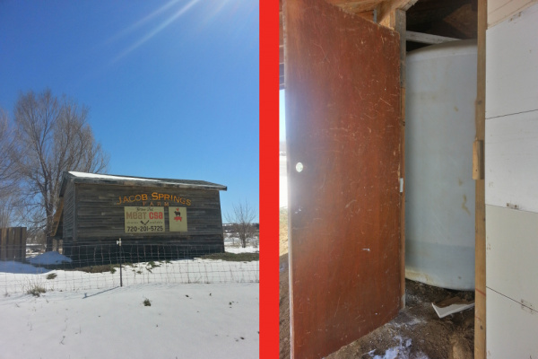
My friend, Andre, owns a CSA farm in Boulder, CO called Jacob Springs Farm. They make some tasty meat, milk, and eggs, so, if you're local, check them out.
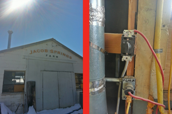
They aren't legally allowed to run a city water line to the property, so they use a well and their own storage tanks. The pump for the well is manually turned on or off using a twist timer (which is actually only rated for 50% of the pump's current load), and typically they have no idea how much water is in the tanks (unless they're empty). I've heard hilariously tragic stories of people being in the shower and having the water run out during winter. They have to run out to the barn, all soaped up and in their towel, turn on the water, and wait for the water heater to fill up and heat so they can finish their shower. Other times the water runs out while preparing dinner or doing dishes, and the low water pressure makes for slow going.
The water tanks are on one corner of the property (the highest elevation), far from any power outlets, and the pump for the well is at the other end. In order to manage the water system for the farm, I've developed this system that measures the water height with an ultrasonic sensor and controls the pump from that data. While I was at it, I added some extra environmental sensors.
Required Materials
This project is two-fold: remote telemetry (measurements) coupled with automated weather warnings, and remote control/automation of a hefty (2 hp) pump. To follow along with this tutorial, you'll need the following products and tools:
Pump Remote Control Box
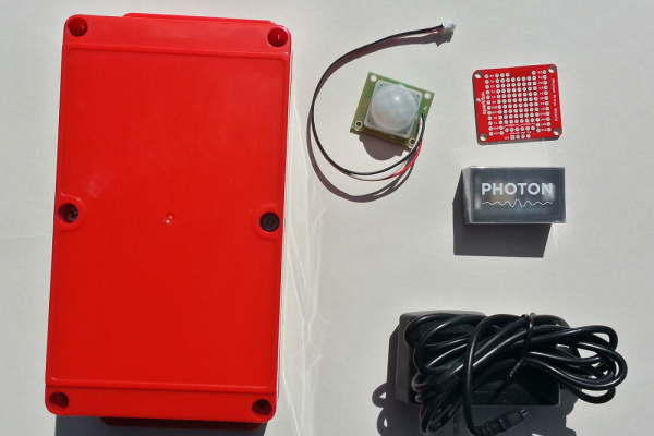
For the automation of the pump, you will need:
- 1 contactor to turn on/off the pump, rated for the pump load (3hp, 2200W in this case, but choose the contactor with an appropriate horsepower rating for your application), or a relay if the load is light enough
- 10A relay to control the contactor
- Particle Photon WiFi MCU to control the relay
- Photon ProtoShield
- female headers
- male-male jumper wires
- 5 V power supply for the photon
- box to hold the photon and relay
- PIR sensor to check if someone is near the control box/contactor
- 10 k resistor for the PIR
- a few mounting screws (5), I used #8 1-1/4" drywall screws, a DIN rail is more professional
- appropriate wiring for your loads (check here for max amperage for different wire gauges) -- I used about 2 ft of 18 AWG for control of the contactor, and about 5ft of 10 AWG for wiring leading to the pump
Remote Telemetry Box (water height, etc)
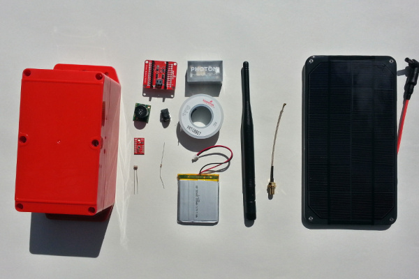
The other half of the project is remote data collection. For this, you will need:
- Particle Photon WiFi MCU
- SMA to u.FL cable (may not be necessary if you can get wifi reception without the antenna)
- Duck Antenna (may not be necessary if you can get wifi reception without the antenna), you can also use a cantenna or yagi antenna for longer-range reception
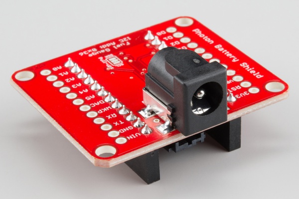
- Photon Battery Shield
- LiPo battery (I used 2000 mAh, but you can go higher or lower capacity depending on budget and how often you want to take measurements)
- solar cell (I used 3.5 W but that's overkill, just to be safe -- if trying to save money, you could use the 2 W)
- CdS photocell
- 1 k resistor for use with the photocell
- BME280 pressure/humidity/temperature sensor
- MaxSonar EZ3 ultrasonic range finder (measures water height), although I recommend the waterproof HRXL for robustness
- box to hold it all
- hookup wire (22 AWG)
- a few mounting screws (2), I used #8 1-1/4" drywall screws
- some twine or wire to hold the solar panel down
Here's a wish list containing all the SparkFun parts used in this project:
Tools
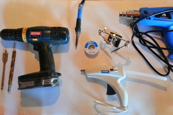
- Drill
- drill bits: 3/4", 5/8", 1/2", 1/8"
- soldering iron, solder, optional: third hand, copper sponge (for cleaning soldering iron tip)
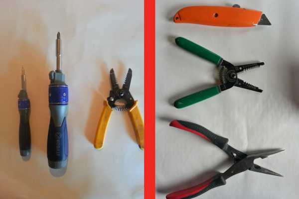
- wire strippers
- hot glue gun and hot glue
- heat gun for shrink wrap (can use hair dryer in a pinch)
- screw driver
- two pairs needle-nosed pliers
- exacto knife
- tape measure
- sledge hammer for driving a grounding rod into the ground
Other Supplies
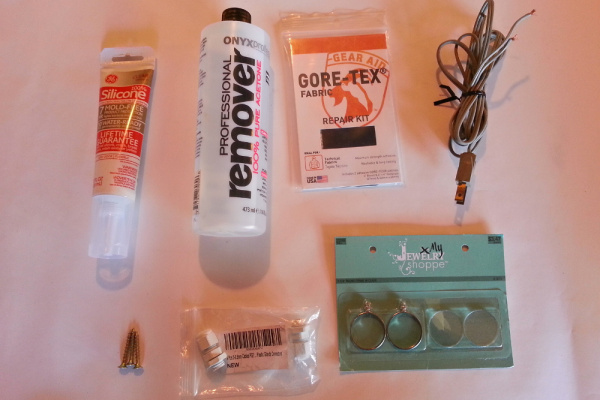
- Gore-Tex® repair patch kit (I sourced locally at REI, but also available here)
- acetone or other solvent to remove adhesive from Gore-Tex® patch (may not need this for the Simms patches)
- 2 PG-7 cable glands
- silicone
- small glass piece, I got mine from Hobby Lobby
- AC cord with bare leads for testing contactor
- aluminum foil (for shielding the ultrasonic sensor from static from the plastic water tank)
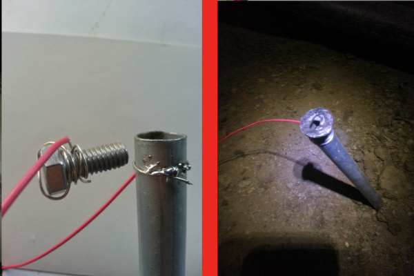
- grounding rod for grounding the aluminum foil housing (I used 1/2" 10' EMT conduit)
Suggested Reading
Before embarking upon this tutorial, you may find the following links useful:
Photon Development Guide
Photon Battery Shield Hookup Guide
Prepping the Photons
The first thing is to get your Photons prepped and ready to accept firmware over WiFi.
If you have never used the Particle Photon before, you will need to visit the Particle website to learn how to setup a Photon for first time use. You will need to connect it to your local network, pair the device with your free Particle cloud account, and possibly update firmware before you will be ready to upload your first program. All of that information can be found at the following link:
Once your Photon setup, you will also need to install the Particle Command Line Interface (CLI) on your computer. This will allow us to watch the serial output from the Photon in our terminal/command console.
Build the Pump Controller
The contactor/relay idea is used here to control a pump for a well, but could also be used to control a solenoid for a sprinkler/watering system (you'd probably only need a relay in that case), or to switch on lights, motors, or pumps in a structure (greenhouse, warehouse, etc), heavy-duty heaters, or other remote control needs you might have.
Triacs, Contactors, and Relays -- Oh My
To begin, let's discuss the various ways to control AC power.
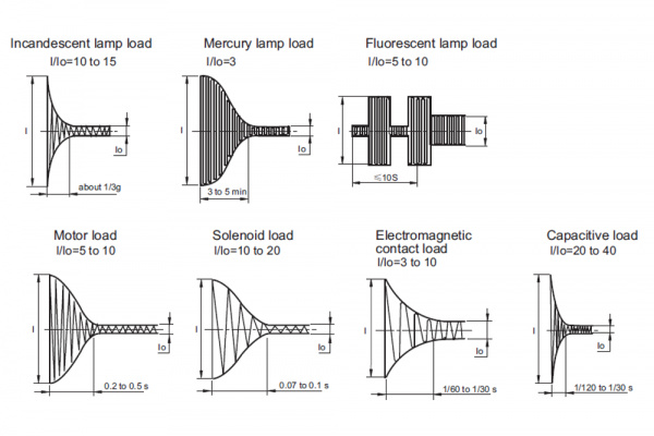
To switch lighter, resistive AC loads (like a small electric heater), a relay can be used. However, once you need to switch a pump on or off, or another inductive load, a different kind of switch is usually needed. Why? It's because when inductive loads start up, they exert a huge load--but only temporarily. See this stackexchange question. Using an undersized relay with an inductive load like a pump can be a dangerous proposition; the heat from the start up of an inductive load could eventually fuse the relay contacts together, leaving your pump constantly on and you not even knowing it.
A triac is another way to control AC with silent operation, though I won't go into any details as this project didn't use any.
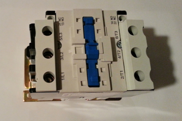
For a beefy motor, like a well pump or other industrial sized applications (like turning on the lights in an entire warehouse, etc), you want to use a contactor. These are rated by [UL](https://en.wikipedia.org/wiki/UL_(safety_organization)) for certain motor loads, like 1 hp (~750 W), 2 hp (~1500 W), etc. In our case, we have a motor that I measured at 1500 W -- about 2 hp. Oversizing electrical components is usually the safest bet, so I picked a 3 hp contactor from US Breaker Inc., which had some of the best prices I could find. The datasheet tells us it can handle 3 hp at 120 V. The coil, which controls the contactor, takes about 2 A at startup and about 0.2 A thereafter, so a 10 A relay is more than enough to handle this, plus we can then easily control this from a MCU. The coil runs off of straight-up 120 V, so we don't need another power supply to control the contactor, just a relay that can switch up to 2 A at 120 V.
The breaker is rated for 800,000 cycles, which should last about 91 years if the breaker is switched every hour (and it will probably be switched much less often). US Breaker has [other contactors that can handle up to 7.5 hp inductive loads (5600 W) at 120 V](https://www.usbreaker.com/miva/merchant.mvc?Screen=SRCH&Store_Code=UBI&Search=%22Chint%20NC1(Contactor)%20Family%22) in case you need more beef.
Electrical Setup
If you're new to soldering check out this tutorial and practice on some scrap parts before trying the real thing. Solder the relay together, if you're using the SparkFun Kit. You can find assembly instructions for the relay kit in this hookup guide.
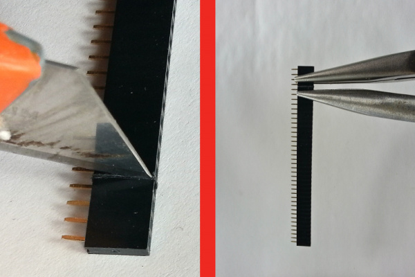
Cut 2 sets of female headers to the correct size (20 units) by first scoring with an exacto knife (I do it on all sides of the headers), then use two pairs of needle-nosed pliers to make a clean break. Score each side a few times to get a deep cut. It will probably take you a few tries to get the hang of it, so don't get discouraged when the first few don't work out.
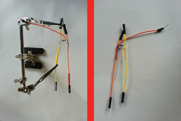
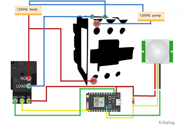
Assemble 3 male-to-male jumpers into a connector for the PIR and relay. There should be a 10kΩ resistor between the 5V (Vin) and dataline for the PIR. The 5V line should be split, one to go to the relay and one to the PIR. Before soldering things together, put some heatshrink on the wires so it is easy to cover up bare wires. After soldering, heat the heatshrink with the heat gun until they tightly grip the wires (don't heat for more than 5-8 seconds).
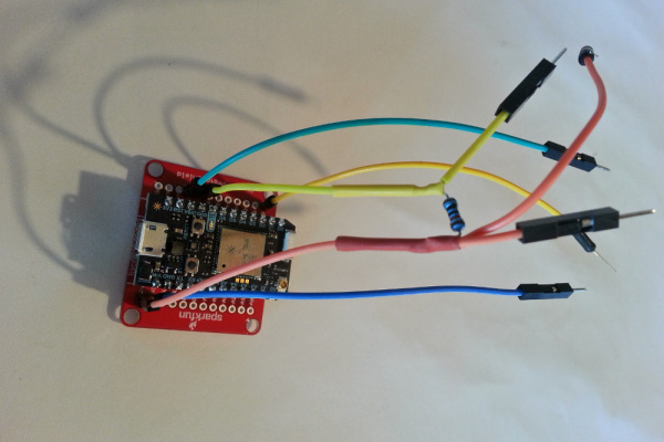
Solder the headers to the ProtoShield. Solder the PIR data header to the D7 hole, the Vcc header to the Vin hole, and the GND header to one of the GND holes. Solder another jumper to the other GND hole and one more jumper to the D0 hole for the relay.
Next, test the relay and contactor to make sure everyone's riding on the gravy train. Connect the GND, Vin, and D0 jumpers to the GND, 5V, and CTRL of the relay board, respectively. Upload the code below (via build.particle.io) to your Photon to test the relay (listen for the clicking every few seconds to make sure it works and watch the LED. You can also test the resistance between the 'load' and 'normally open' screw terminals on the relay to make sure it goes between 0 and infinity if you wish.
language:c
void setup() {
    pinMode(0, OUTPUT);
}

void loop() {
    digitalWrite(0, HIGH);
    delay(2000);
    digitalWrite(0, LOW);
    delay(2000);
}
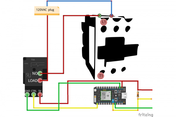
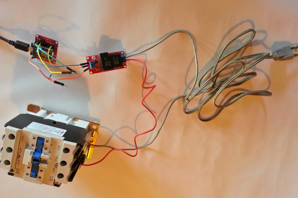
Next is the contactor. Hook up some wire from an AC plug to the relay terminal, then from the other relay terminal to the contactor A1 connector, and last the other end of the AC wire to the contactor A2 terminal. Run the relay test again and make sure the contactor is switching. You will definitely notice when the contactor is working, as it clicks on and off with authoritah. You can again use a multimeter to watch the resistance between some of the 'T' and 'L' terminals if you wish; it should drop from 1 to 0 when the relay is on.
Not surprisingly, the beefy contactor is much louder than the relatively cutesy little relay.
Connect the PIR sensor to the Photon: connect the D7 jumper to the signal line (black wire), the Vin to the red wire, and the white wire to GND. There's a tutorial here explaining more about this sensor, but it's pretty simple -- when motion is detected, the output pin from the sensor pulls low. Power up the Photon, and upload this code:
language:c
void setup() {
    pinMode(7, INPUT);
}

void loop() {
    int pirVal = digitalRead(7);
    if(pirVal == LOW){
        Serial.println("Motion Detected");
        delay(2000);
    }
}
Check to make sure the PIR sets off the alarm when you wave your hand in front of it. You can tell if it's working because the D7 LED will light up when the alarm is triggered. Additionally, you can type 'particle serial monitor' in your terminal/command console (with the Photon plugged into your computer via USB) to watch the serial output from the device, which should print 'Motion Detected' when you wave your hand in front of it.
Physical Construction
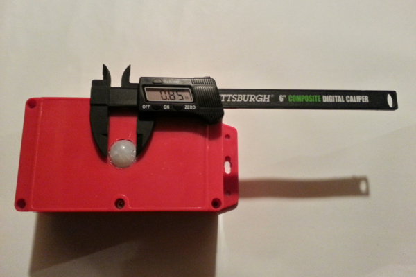
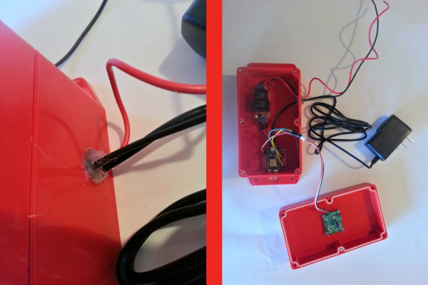
First, drill a hole in the front of the case for the PIR sensor. The PIR sensor used here has a diameter of about 0.85", or 21.5 mm, so I used a 3/4" drill bit and widened the hole with the 1/2" drill bit. I hot-glued the PIR in there. Add some hot glue on the corners of the board to hold it to the red box. For a more secure job, drill holes, and use 2mm screws and nuts to secure the board to the case.
Next, drill a 1/2" hole in the side of the case. Drill some 1/8" holes for mounting the ProtoShield and relay, if you want to secure the board with 6-32 screws or a similar size. For ease and quickness, I just hotglued the boards to the box.
String the 5V power supply cord through the 1/2" hole we drilled in the side of the enclosure, and plug the micro-USB power cord into the Photon. If you want to be more professional, use a PG-7 cable gland to string the wires through. Attach some wires to the relay, leaving enough length to connect to the AC leads in your field installation (I used 18-gauge wire, since this will only be carrying about 0.2A at steady-state). If you drilled mounting holes for the relay and protoboard earlier, secure the boards using screws. Otherwise, use a hot glue gun to attach the boards to the case. Finally, hot glue the wires through the hole for strain relief and to prevent pull-out of the wires from the relay.
Finally, screw the box together with the six screws on top.
Field Installation
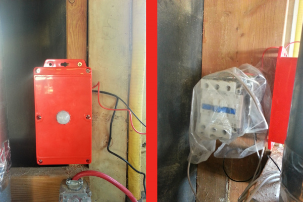
Use some screws to attach the box to a wall near your pump and AC leads and some screws as mounting for the contactor, if you're not going with a DIN rail. I used some extra screws we had laying around, they seem like #8 1-1/4" drywall screws, and I drilled shallow 1/8" pilot holes before screwing them in.
Once the contactor screws are in, hang the contactor on them, and tighten the screws so that the contactor won't be rattling around much. Take the contactor back off, attach your wires to the terminals L1, T1, A1, A2, and the GND terminal (you will ideally want a small bolt/nut for this GND connection, seems like 6-32 with ½" length would work). If you're going to be in a dusty area (for example, we're in a wood shop) use protection and cover the contactor with plastic, etc. Finally, hook up the wires correctly to the pump and power cord, as shown in the full circuit diagram below.
Run the relay test program from earlier to verify everything is working.
We'll come back to data collection and automation of the pump control after installing the remote sensor.
Build the Remote Telemetry Box
Energy Considerations -- Battery and Solar Cell Sizing
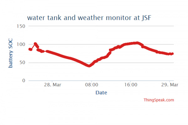
The plan is to periodically wake up the Photon to take a measurement, then put it into deep sleep if the battery level is not very full. The Photon energy use specs are here. The maximum average WiFi operating current is 100mA, and the maximum deep sleep operating current is 0.1mA. Assuming an on time of 60 seconds and an off time of 5 minutes, we use about 400mAh per day. If we want to have the Photon last for three days without any sunlight (sometimes it can blizzard here for a day or two), we need at least 1200mAh of battery capacity. The nearest battery size available from SparkFun, rounding up, is 2000mAh. However, you can play with the sleep cycle time by copying this spreadsheet and get down to a pretty small battery size. Also, by sleeping the Photon longer at night when there's less water usage, we can extend the battery life dramatically.
| Pin Label | Pin Description |
|---|---|
| 1 | Switch contact 1 |
| 2 | Switch contact 2 |
| + | LED anode |
| - | LED cathode |
A Watt = V * A, so our 3.5W solar cell providing power at 5V is pushing 0.7A. We should be able to charge our 2000mAh battery pretty quickly (about 3h) under ideal conditions. However, the cell will get dusty, days will be cloudy, etc, so it's best to oversize when in doubt. If you want to save some bucks, the 2W solar cell should push about 0.4A under ideal conditions.
Physical Construction
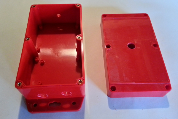
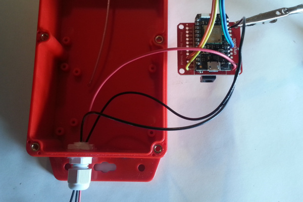
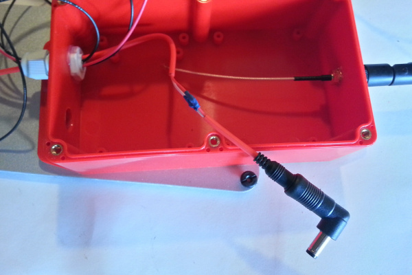
Drill ½" holes for the cable gland and pressure/humidity hole on the side of the box you expect to get the least rainfall/water exposure, and a ¼" hole for the antenna on the same side. Drill another ½" hole in the lid of the box for the photocell window. I accidentally installed the antenna on the top of the box, where rain will hit it directly. If you want to mount the battery shield with 6-32 screws, drill some 1/8" holes as well on the bottom of the box. Put silicone around the photocell hole on the cover and press the glass on the outside of the hole. Put silicone around the cable gland hole and the antenna hole, and install both of them.
Waterproof Holes
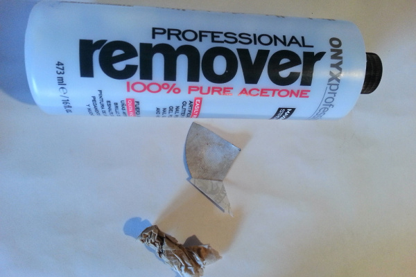
We need a hole to let humidity, pressure, and temperature equilibrate with our BME280 sensor, but we don't want to let rain water in. The solution I came up with is to use a GoreTex repair patch pad and to use a solvent to get rid of the adhesive on the area that lets humidity through. Most solvents you've got laying around should be fine (acetone, mineral spirits, goof-off, ethanol--such as Everclear), but check with this chart before trying any solvents not mentioned here. Take a rag, paper towel or napkin, douse it with some acetone, and rub off the adhesive on the back of the repair patch. This will dissolve the adhesive after a bit of work. When you can touch the spot you've treated and don't feel the sticky adhesive, you're probably good. I'm not sure if the adhesive lets moisture and pressure through very well or not, as I haven't tested, but, once the adhesive is removed, it works well.
Put a bit of silicone around the hole just to make sure it gets sealed well, and apply the patch.
Electrical Hookup
Battery Shield
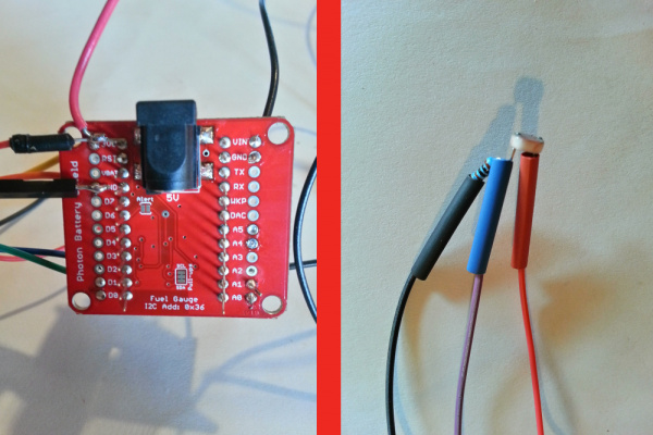
Solder the four legs of the SMD barrel jack plug to the board, as described here.
You can test it with the MAX17043 library. Details on using the battery shield are beyond the scope of this project tutorial, as that information can be found in the Battery Shield Hookup Guide.
BME 280 Pressure, Humidity, Temperature
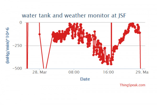
The BME280 can read pressure, humidity, and temperature, so it makes a nice mini weather station. Changes in air pressure are an easy way to predict incoming storms (unless you're in a more tropical climate, like the gulf coast). We can use some guidelines to classify pressure changes on the hour timescale, and we'll post that information to a Twitter account. Basically, if pressure is dropping, the rate of the drop indicates how soon a storm is likely on the way. Dropping air pressure usually also means rising wind speeds; rising pressure usually means good weather.
Here's a table of pressure drop over three hours that we're going to use to classify our data, referenced from here:
| Classification | min pressure rate (inHg/min * 10^6) | max pressure (inHg/min *10^6) | lower limit % change over 3 hours |
|---|---|---|---|
| Steady | 0 | 16 | 0 |
| Changing slowly | 16 | 246 | 0.01 |
| Changing moderately | 246 | 574 | 0.15 |
| Changing rapidly | 574 | 984 | 0.35 |
| Changing very rapidly | 984 | 0.59 |
Essentially, if we have a 0.6% change in pressure in three hours, the pressure is changing very rapidly and bad weather may be on the way. We'll post to a Twitter account and set up text alerts for when pressure is dropping very rapidly. The spreadsheet for the calculations is here, in case you want copy it and mess with it.
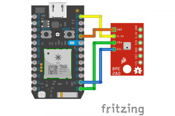
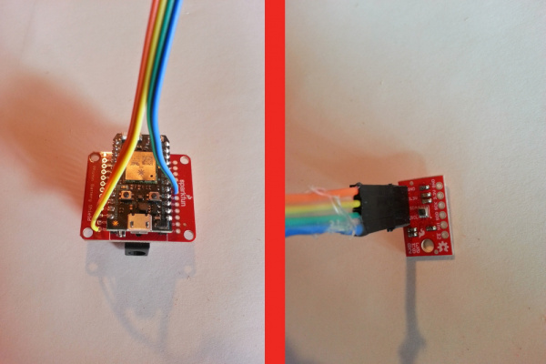
Solder some M-M jumpers to the BME280 board, and solder the other ends to GND, 3.3V, and D0/D1 (SDA/SCL) pins on the battery shield, respectively.
Start a new Photon project on www.build.particle.io, include the library "SPARKFUNBME280" (click the 'Libraries' icon on the left, search in the box for BME280, click the SPARKFUNBME280 library, click 'Include in App', click the name of your app, click 'Add to App') and upload this code to your photon to test the sensor:
language:c
/******************************************************************************
I2C_and_SPI_Multisensor.ino
BME280 Particle Photon example

Sensor A is I2C and connected through D0/D1 (SDA/SCL)
******************************************************************************/

#include "SparkFunBME280/SparkFunBME280.h"

BME280 mySensorA;

void setup()
{
    // set up sensor
    mySensorA.settings.commInterface = I2C_MODE;
    mySensorA.settings.I2CAddress = 0x77;
    mySensorA.settings.runMode = 3; //  3, Normal mode
    mySensorA.settings.tStandby = 0; //  0, 0.5ms
    mySensorA.settings.filter = 0; //  0, filter off
    //tempOverSample can be:
    //  0, skipped
    //  1 through 5, oversampling *1, *2, *4, *8, *16 respectively
    mySensorA.settings.tempOverSample = 1;
    //pressOverSample can be:
    //  0, skipped
    //  1 through 5, oversampling *1, *2, *4, *8, *16 respectively
    mySensorA.settings.pressOverSample = 1;
    //humidOverSample can be:
    //  0, skipped
    //  1 through 5, oversampling *1, *2, *4, *8, *16 respectively
    mySensorA.settings.humidOverSample = 1;


    delay(6000); // so you have time to start the serial monitor and see the initial output
    Serial.print("Program Started\n");
    Serial.println("Starting BME280s... result of .begin():");
    delay(10);  //Make sure sensor had enough time to turn on. BME280 requires 2ms to start up.
    //Calling .begin() causes the settings to be loaded
    Serial.print("Sensor A: 0x");
    Serial.println(mySensorA.begin(), HEX);
}

void loop()
{
    //Start with temperature, as that data is needed for accurate compensation.
    //Reading the temperature updates the compensators of the other functions
    //in the background.
    Serial.print("Tempferature: ");
    Serial.print(mySensorA.readTempC(), 2);
    Serial.println(" degrees C");

    Serial.print("Temperature: ");
    Serial.print(mySensorA.readTempF(), 2);
    Serial.println(" degrees F");

    Serial.print("Pressure: ");
    Serial.print(mySensorA.readFloatPressure(), 2);
    Serial.println(" Pa");

    Serial.print("Pressure: ");
    Serial.print(mySensorA.readFloatPressure()*29.529983/100000, 2);
    Serial.println(" inHg");

    Serial.print("Altitude: ");
    Serial.print(mySensorA.readFloatAltitudeMeters(), 2);
    Serial.println("m");

    Serial.print("Altitude: ");
    Serial.print(mySensorA.readFloatAltitudeFeet(), 2);
    Serial.println("ft");

    Serial.print("%RH: ");
    Serial.print(mySensorA.readFloatHumidity(), 2);
    Serial.println(" %");

    Serial.println();

    delay(2000);

}
Type 'particle serial monitor' in your command prompt/terminal, and check to make sure the output is reasonable and working.
CdS Photocell
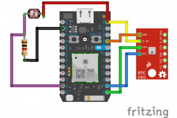
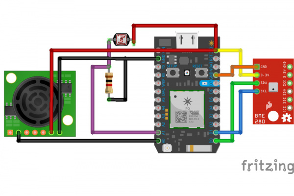
To measure light levels, we'll use a CdS photocell. We're going to use a 1 k resistor as a pull-down. Information on how to use a photocell can be found here. Solder the connections as so:
It ended up being tough for me to place the CdS cell in the glass window because my wires were too short, so leave yourself some extra room with at least eight inches of wiring between the battery shield and the CdS cell.
Test the reading of the photocell with a flashlight, using this code:
language:c
void setup() {
    pinMode(A1, INPUT);
}

void loop() {
    float lightIntensity = analogRead(A1);
    Serial.println(lightIntensity);
    delay(1000);
}
Check the serial output with 'particle serial monitor', and make sure the number goes up when you shine a bright light on it. The number should read in the thousands; the range of the Photon analog signal is from 0 to 4095, so make sure the reading isn't near 4095 unless you're in broad daylight or close to a bright LED. There's a nice classification of voltage output levels for different lighting conditions here.
Sensing Distance (Water Height) with an Ultrasonic Sensor
Because air and water have different densities, the water reflects some of the ultrasonic waves sent at it, for example, by something like the MaxSonar-EZ3 sensor (manufacturer's page here). Again, I recommend the waterproof version for reliability.
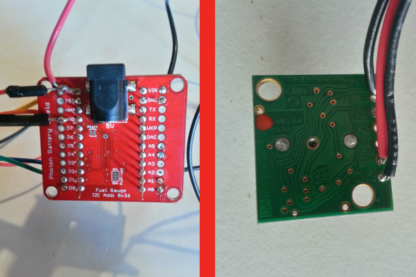
To add this part to the telemetry box, first measure the distance from where you will put the telemetry box to where the ultrasonic sensor will go, and cut three sufficient lengths of wire. I used 22 AWG hookup wire and ended up with about 8 to 10 ft of wire. Solder the wires to the GND, +5, and PW holes on the device, by soldering the ends of the wires. Pass the wires through the cable gland, and solder the other ends of the wires to the battery shield: GND, 3.3V (or Vin), and A0.
Test the device by uploading this code to your Photon:
language:c
float uSperInch = 147; // from datasheet
float distance;
unsigned long duration;

void setup() {
    pinMode(A0, INPUT);
}

void loop() {
    duration = pulseIn(A0, HIGH);
    Serial.print("pulse length: ");
    Serial.println(duration);
    distance = duration / uSperInch;
    Serial.print(distance);
    Serial.println(" in");
    delay(1000);
}
The datasheet from the manufacturer's page says the pulse width is 147uS/inch, and it seemed to be right around there for me. Double check the readings with a measuring tape though.
Finishing the Telemetry Box
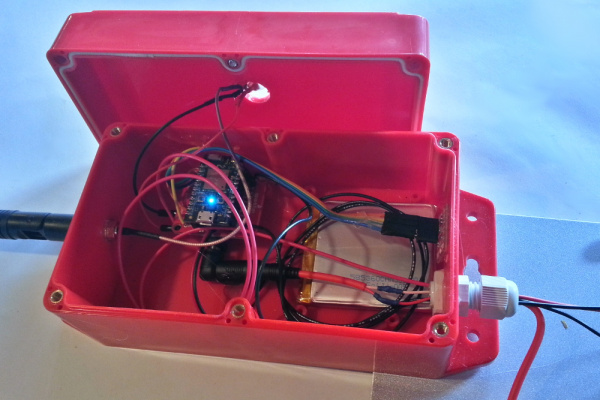
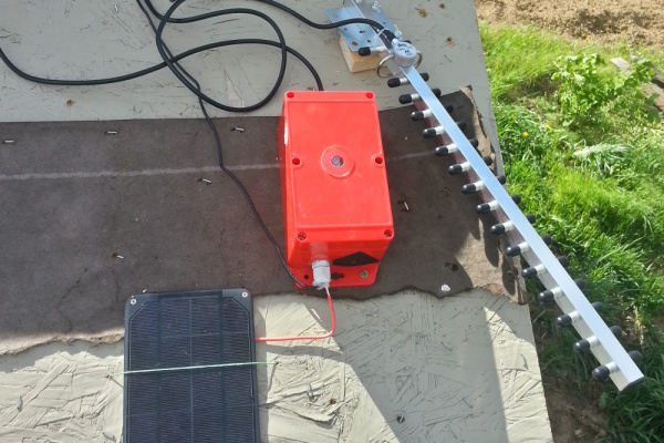
The few last things to do are pass through the solar cell barrel jack, stuff everything in the box (maybe with a little hot glue), and make sure all the external holes look well sealed up.
We have to cut the solar cell wire in two, and, using your wire strippers, strip each wire down. Then pass the wires through the cable gland and solder them back together. I used heat shrink to make the connections clean. The solar cell cable length is very short, so you might want to add some extensions. You could also add enough of an extension so that the box is in the shade (so it doesn't get too hot, especially if you're in the desert).
Finally, connect the battery and the solar cell to the Battery Shield, and put everything in the box as best you can. I hot-glued most things down, but in the sun, things get pretty hot (as we'll see from the measurements), so the glue tends to un-stick. I did hot-glue the CdS cell to the glass window, and even after it un-stuck (and I reopened the box), it was still pretty easy to put back in the window due to the shape of the glue. Lastly, tighten the six screws down on the top of the box, tighten the cable gland, and maybe put some silicone on the cable gland to make sure it's good and waterproof.
Field Installation
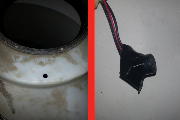
Put the box and solar cell in a place that's going to get some sun. String the wires from the box through to the water tank. This is where things get tricky. If you have giant plastic water tanks, like we do, you'll likely get static electricity buildup that will interfere with the measurements. As long as the sensor isn't touching the tank (I also covered the sensor in aluminum foil and grounded it with a ground rod), it should be ok. If the tank isn't plastic, you can drill a 5/8" hole somewhere in the tank. I covered most of the ultrasonic sensor with black electrical tape as a bit of protection.
If your tank is outside, you will probably be getting condensation at times. The waterproof sensor may fix this problem, otherwise, mount the non-waterproof sensor above the tank (with a hole to let the ultrasound pass into the tank) so that condensation won't be happening on the sensor.
The water tanks on the property where this was installed are gigantic plastic (polyethylene, probably) tanks. The pump is about a half mile away, and the whole distance is bridged by PVC pipe. Possibly due to this, there seems to some static buildup in the system. As evidence, I've felt a massive static field (6-12 inches above the tank) before while climbing on top of the tanks. This appeared to be effecting the ultrasonic sensor, as it would perform great in lab tests, but out in the field it would get wonky after a few measurements (reading values smaller than the minimum distance), and correct measurements would come and go during the day and night. Things seemed to go haywire after the water started flowing for an hour or two--in either direction, in or out.
The other strange thing about this whole deal is when I would plug the photon into my computer, the readings would be OK again, and when I unplugged it, they would go back to being very small and incorrect.
To combat this, I drove a 10ft 1/2" EMT conduit rod about nine feet into the ground with a sledge hammer. I took a wire and connected one end to the EMT conduit. On the other end, I tied a stainless steel bolt to it and dropped it in the water tank. I also tied a wire around the ultrasonic sensor's plastic housing and connected it to the EMT rod. It seemed to help somewhat, but still didn't completely fix the problem.
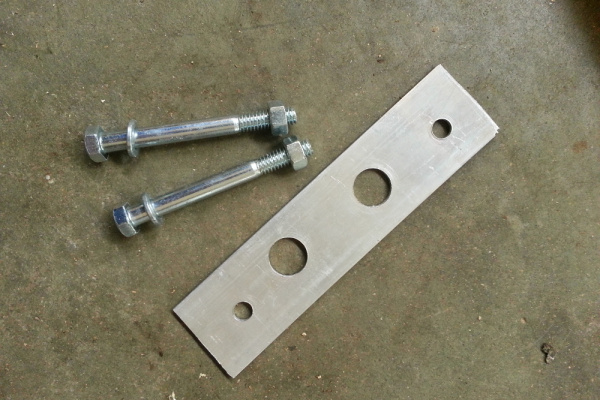
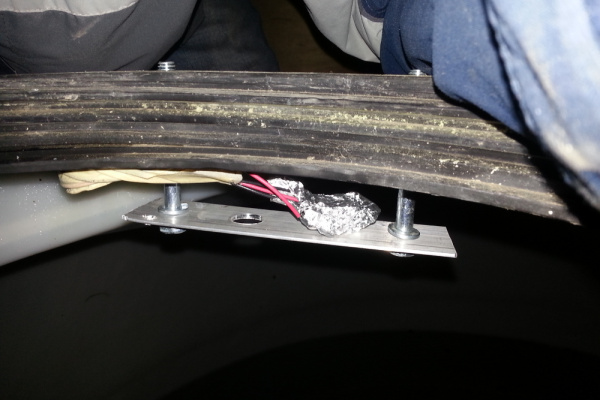
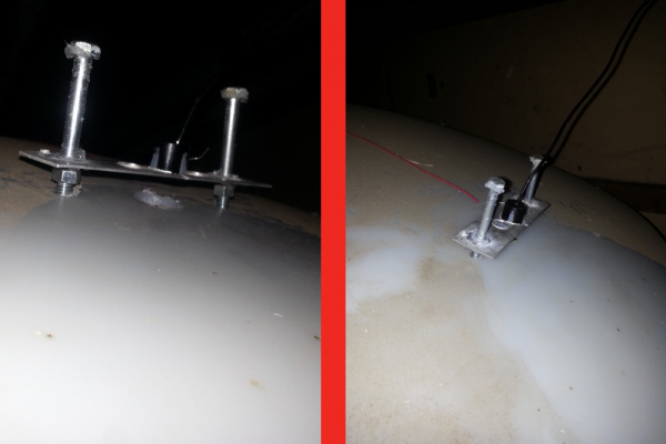
The only way I was able to get the sensor to reliably read water height was to suspend it above the tank, without the plastic housing touching the water tanks. I wrapped the sensor in aluminum foil (except the front face) and attached the ground wire to the foil. I then drilled some holes in a 1.5" aluminum flat bar, attached the bar to the water tank, and attached a grounding wire to the bar. After that, the readings were stable.
However, after a few days, the readings started going haywire. I found there was condensation on the sensor that caused this. If your water tank is outside, mount the sensor above the tank (using something like the metal plate I used), and put a hole in the tank (larger than the sensor diameter), directly below the sensor.
Some people claim plastic can't be grounded, and they may be right. However, adding a grounding lug at the inlet to the tank may work, although I haven't tried this.
Using the waterproof HRXL sensor may completely bypass the static electricity problem; I'm not sure. In any case, it would be a better idea for long-term robustness to use the waterproof sensor.
Finally, you need to know the distance from the bottom of the tank to the front of the sensor, so get out your measuring tape and check that now, and make a note of it. To get the water height, we simply take the total water tank height and subtract the distance read from the ultrasonic sensor.
The Code
The code for this project lives on GitHub. You can find all the latest by following the link below.
Minimum Viable Product
In the startup world, a minimum viable product (MVP) is something that gets the job done and nothing more. I'll give you an example of the MVP for the setup we've built here.
Particle Publish and Subscribe
Using the function Particle.Publish(), we can quickly toss up a variable online so other Photons or devices can use it. In this example it will be used to send the water height and let our pump control box know the water height sensor is still online, and it can also be used to send commands, like 'turn on the pump', or 'don't deep sleep our telemetry Photon quite yet'.
The format of a publish is MQTT-like. A subscription works like a prefix filter. If you subscribe to "foo", you will receive any event whose name begins with "foo", including "foo", "fool", "foobar", and "food/indian/sweet-curry-beans".
I set up my prefix organization and subscribes as so:
language:c
Particle.subscribe("jsf/waterSystem/", eventHandler, MY_DEVICES);
If I want the water height sensor to tell the control box that it's still online, I would do:
language:c
Particle.publish("jsf/waterSystem/waterTankSensor/online", "true");
You can also use the 'private' flag with your publishes, and use the 'MY_DEVICES' flag with your subscribes, if you want to improve security.
Depending on your situation, you may be sleeping the telemetry Photon for a long time and only have it on for a few minutes or seconds. In this case, it makes updating the software tough. For that, I created a Python script that senses when the Photon comes online and tells it to wait a bit for a software update. If you want to use it, install Python -- I like using Python(x,y) for Windows, and run this script (first install sseclient, requests, and json using [pip](https://en.wikipedia.org/wiki/Pip_(package_manager)) or easy_install; type 'easy_install sseclient' or 'pip install sseclient' in your command prompt or terminal for sseclient, requests, and json):
language:python
from sseclient import SSEClient
import requests, re, json

access_token = "YOUR ACCESS TOKEN HERE"
publish_prefix_head = "myFarm" # for subscribing to incoming messages, e.g. myFarm
publish_prefix = "myFarm/waterSystem" # e.g. myFarm/waterSystem
messages = SSEClient('https://api.spark.io/v1/events/' + publish_prefix_head + '?access_token=' + access_token)
r = requests.post('https://api.particle.io/v1/devices/events', data = {"name":publish_prefix + "/waterTankSensor/update", "data":"true", "private":"false", "ttl":"60", "access_token":access_token})
if r.json()['ok']==True:
    print 'successfully sent update request'


with open('recorded messages.txt', 'w') as record:
    for msg in messages:
        event = str(msg.event).encode('utf-8')
        data = str(msg.data).encode('utf-8')
        if re.search('jsf', event):
            dataJson = json.loads(data)
            if event == publish_prefix + '/waterTankSensor/online' and dataJson['data'] == "true":
                r = requests.post('https://api.particle.io/v1/devices/events', data = {"name":publish_prefix + "/waterTankSensor/update", "data":"true", "private":"false", "ttl":"60", "access_token":access_token})
                if r.json()['ok']==True:
                    print 'successfully sent update request'
            if event == publish_prefix + '/waterTankSensor/updateConfirm':
                if dataJson['data'] == 'waiting for update':
                    print 'device waiting for update...'
                if dataJson['data'] == 'not waiting for update':
                    print 'device no longer waiting for update.'
Save the code in a file called 'updatefirmware.py', and, once you type 'python updatefirmware.py' (from the same directory the file is located in, of course), it will print some messages out. When the device is waiting for an update, it will print 'device waiting for update...'. Then you can head to build.particle.io, and flash your device.
Telemetry Box
Create a new Photon app on build.particle.io, and include the ThingSpeak library in it (make sure it's the "ThingSpeak" library, and not the "thingspeak" library--note the capitalization). Right now it shows up as the first result from searching for 'things'. Also include the SPARKFUNMAX17043 and SPARKFUNBME280 libraries. Here is the full code:
language:c
#include "SparkFunBME280/SparkFunBME280.h"
BME280 mySensorA;
float tempF;
float pressure;
float RH;

#include "SparkFunMAX17043/SparkFunMAX17043.h"
// MAX17043 battery manager IC settings
float batteryVoltage;
float batterySOC;
bool batteryAlert;

#include "ThingSpeak/ThingSpeak.h"
//################### update these vars ###################
unsigned long myChannelNumber = your channel number here;  //e.g. 101992
const char * myWriteAPIKey = "your api key here"; // write key here, e.g. ZQV7CRQ8PLKO5QXF
//################### update these vars ###################
TCPClient client;
unsigned long lastMeasureTime = 0;
unsigned long measureInterval = 60000; // can send data to thingspeak every 15s, but give the matlab analysis a chance to add data too

// ultrasonic distance sensor for water height measurement
float uSperInch = 147; // from datasheet
float distance;
unsigned long duration;
float waterHeight;
//################### update these vars ###################
float totalDistance = 64; // the distance from the sensor to the bottom of the water tank
//################### update these vars ###################

// photocell
float lightIntensity;

// connection settings
STARTUP(WiFi.selectAntenna(ANT_EXTERNAL)); // use the u.FL antenna, get rid of this if not using an antenna
float batterySOCmin = 40.0; // minimum battery state of charge needed for short wakeup time
unsigned long wakeUpTimeoutShort = 300; // wake up every 5 mins when battery SOC > batterySOCmin
unsigned long wakeUpTimeoutLong = 900; // wake up every 15 mins during long sleep, when battery is lower
unsigned long connectedTime; // millis() at the time we actually get connected, used to see how long it takes to connect
unsigned long connectionTime; // difference between connectedTime and startTime

// for updating software
bool waitForUpdate = false; // for updating software
unsigned long updateTimeout = 600000; // 10 min timeout for waiting for software update
unsigned long communicationTimeout = 300000; // wait 5 mins before sleeping
unsigned long bootupStartTime;

// for publish and subscribe events
//################### update these vars ###################
String eventPrefix = "your prefix"; // e.g. myFarm/waterSystem
//################### update these vars ###################

bool pumpOn;

void setup() {
    // Set up the MAX17043 LiPo fuel gauge:
    lipo.begin(); // Initialize the MAX17043 LiPo fuel gauge

    // Quick start restarts the MAX17043 in hopes of getting a more accurate
    // guess for the SOC.
    lipo.quickStart();

    // We can set an interrupt to alert when the battery SoC gets too low.
    // We can alert at anywhere between 1% - 32%:
    lipo.setThreshold(20); // Set alert threshold to 20%.
    // use this to measure how long it takes to connect the Photon to the internet if you're in spotty wifi coverage
    pinMode(A0, INPUT); // ultrasonic distance sensor

    // set up BME280 sensor
    mySensorA.settings.commInterface = I2C_MODE;
    mySensorA.settings.I2CAddress = 0x77;
    mySensorA.settings.runMode = 3; //  3, Normal mode
    mySensorA.settings.tStandby = 0; //  0, 0.5ms
    mySensorA.settings.filter = 0; //  0, filter off
    //tempOverSample can be:
    //  0, skipped
    //  1 through 5, oversampling *1, *2, *4, *8, *16 respectively
    mySensorA.settings.tempOverSample = 1;
    //pressOverSample can be:
    //  0, skipped
    //  1 through 5, oversampling *1, *2, *4, *8, *16 respectively
    mySensorA.settings.pressOverSample = 1;
    //humidOverSample can be:
    //  0, skipped
    //  1 through 5, oversampling *1, *2, *4, *8, *16 respectively
    mySensorA.settings.humidOverSample = 1;
    mySensorA.begin();

    ThingSpeak.begin(client);

    Particle.subscribe(eventPrefix, eventHandler);
    Particle.publish(eventPrefix + "/waterTankSensor/online", "true"); // subscribe to this with the API like: curl https://api.particle.io/v1/devices/events/temp?access_token=1234
    bootupStartTime = millis();
    doTelemetry(); // always take the measurements at least once
}

void loop() {
    if (waitForUpdate || millis() - bootupStartTime > communicationTimeout || batterySOC > 75.0 || pumpOn) {
        // The Photon will stay on unless the battery is less than 75% full, or if the pump is running.
        // If the battery is low, it will stay on if we've told it we want to update the firmware, until that times out (updateTimeout)
        // It will stay on no matter what for a time we set, stored in the variable communicationTimeout
        if (millis() - lastMeasureTime > measureInterval) {
            doTelemetry();
        }
            if ((millis() - bootupStartTime) > updateTimeout) {
                waitForUpdate = false;
            }
    } else {
            if (batterySOC < batterySOCmin) {
                System.sleep(SLEEP_MODE_DEEP, wakeUpTimeoutLong);
            } else {
                System.sleep(SLEEP_MODE_DEEP, wakeUpTimeoutShort);
            }
    }
}

void eventHandler(String event, String data)
{
  // to publish update: curl https://api.particle.io/v1/devices/events -d "name=update" -d "data=true" -d "private=true" -d "ttl=60" -d access_token=1234
  if (event == eventPrefix + "/waterTankSensor/update") {
      (data == "true") ? waitForUpdate = true : waitForUpdate = false;
      if (waitForUpdate) {
        Serial.println("wating for update");
        Particle.publish(eventPrefix + "/waterTankSensor/updateConfirm", "waiting for update");
      } else {
        Serial.println("not wating for update");
        Particle.publish(eventPrefix + "/waterTankSensor/updateConfirm", "not waiting for update");
      }
  } else if (event == eventPrefix + "/waterTankPump/pumpOn") {
      (data == "true") ? pumpOn = true : pumpOn = false;
  }
  Serial.print(event);
  Serial.print(", data: ");
  Serial.println(data);
}

void doTelemetry() {
    // let the pump controller know we're still here
    Particle.publish(eventPrefix + "/waterTankSensor/online", "true");

    // water height
    duration = pulseIn(A0, HIGH);
    distance = duration / uSperInch; // in inches
    waterHeight = totalDistance - distance;
    ThingSpeak.setField(1, waterHeight);

    Particle.publish(eventPrefix + "/waterTankSensor/waterHeight", String(waterHeight));

    // BME280
    pressure = mySensorA.readFloatPressure()*29.529983/100000.0;
    ThingSpeak.setField(2, pressure);
    tempF = mySensorA.readTempF();
    ThingSpeak.setField(4, tempF);
    RH = mySensorA.readFloatHumidity();
    ThingSpeak.setField(5, RH);

    // photocell
    lightIntensity = analogRead(A1);
    ThingSpeak.setField(6, lightIntensity);

    // read battery states
    batteryVoltage = lipo.getVoltage();
    ThingSpeak.setField(7, batteryVoltage);
    // lipo.getSOC() returns the estimated state of charge (e.g. 79%)
    batterySOC = lipo.getSOC();
    ThingSpeak.setField(8, batterySOC);
    // lipo.getAlert() returns a 0 or 1 (0=alert not triggered)
    //batteryAlert = lipo.getAlert();

    ThingSpeak.writeFields(myChannelNumber, myWriteAPIKey);
    lastMeasureTime = millis();
}
Variables you should change when you do this:
- eventPrefix (e.g. myFarm/waterSystem; for publish/subscribe events)
- myWriteAPIKey (grab from your ThingSpeak telemetry channel)
- myChannelNumber (from ThingSpeak telemetry channel)
- totalDistance (the distance from the sensor to the bottom of the water tank
I've bracketed these variables with:
language:c
//################### update these vars ###################
so you know what you have to change.
Additionally, you can adjust the batterySOCmin and wakeupTimeout variables if you use a different sized battery.
Control Box
Again, include the ThingSpeak library. Use this code, changing variables where applicable:
language:c
#include "ThingSpeak/ThingSpeak.h"
// channel we're writing to
//################### update these vars ###################
unsigned long myWriteChannelNumber = your channel number; // e.g 101223
const char * myWriteAPIKey = "your write API key for the pump controller channel";
//################### update these vars ###################
TCPClient client;
unsigned long lastMeasureTime = 0;
unsigned long measureInterval = 60000; // can send data to thingspeak every 15s, but once a minute is fine

bool pumpOn = false;
float waterHeight = 1000; // we want to make sure the relay isn't falsely triggered on from the get-go
//################### update these vars ###################
float lowerCutoff = 20; // lowest acceptable water height, in inches
float higherCutoff = 42; // highest acceptable water height, in inches
float totalDistance = 64; // the distance from the sensor to the bottom of the water tank
//################### update these vars ###################
int success;
unsigned long relayStartTime;
unsigned long lastSignal = millis();
unsigned long pumpTimeout = 900000; // turn off the pump if haven't heard from sensor in 15 mins
unsigned long pumpOffTime = 3600000; // make sure we don't turn on the pump more than once per hour
long pumpOffTimeStart = -pumpOffTime; // so we can turn on pump when we startup if we need to

// PIR motion sensor
int relayPin = 0;
int PIRpin = 7;
int PIRval;

// for publish and subscribe events
//################### update these vars ###################
String eventPrefix = "myFarm/waterSystem"; // e.g. myFarm/waterSystem
//################### update these vars ###################

void setup() {
    pinMode(relayPin, OUTPUT);
    pinMode(PIRpin, INPUT_PULLUP);
    digitalWrite(relayPin, LOW);

    Particle.subscribe(eventPrefix, eventHandler);

    ThingSpeak.begin(client);
}

void loop() {
    autoPumpControl();
    checkPIR();
    recordThingSpeakData();
}

int relayControl(String relayState)
{
    if (relayState == "on") {
        pumpOn = true;
        digitalWrite(relayPin, HIGH);
        relayStartTime = millis();
        ThingSpeak.setField(1, 1); // our "pump on" field
        return 1;
    }
    else if (relayState == "off") {
        pumpOn = false;
        digitalWrite(relayPin, LOW);
        ThingSpeak.setField(1, 0); // our "pump on" field
        return 1;
    }
    else {
        return 0;
    }
}

void autoPumpControl() {
    if (pumpOn) {
        if (millis() - lastSignal > pumpTimeout) { // if we haven't heard from the water tanks in a while, turn off the pump
            relayControl("off");
        }
    }
    if (waterHeight < lowerCutoff) {
        success = relayControl("on");
    } else if (waterHeight > higherCutoff) {
        success = relayControl("off");
    } else {
        ThingSpeak.setField(1, boolToNum(pumpOn)); // our "pump on" field
    }
}

void checkPIR() {
    PIRval = digitalRead(PIRpin);
    if(PIRval == LOW){
        ThingSpeak.setField(2, 1); // 1 = motion detected, 0 = no motion
    }
}

void recordThingSpeakData() {
    if (millis() - lastMeasureTime > measureInterval) {
        ThingSpeak.writeFields(myWriteChannelNumber, myWriteAPIKey);
        ThingSpeak.setField(2,0); // reset PIR motion sensor field to 'no motion detected'
        lastMeasureTime = millis();
        Particle.publish(eventPrefix + "/waterTankPump/pumpOn", boolToText(pumpOn));
    }
}

String boolToText(bool thing)
{
    String result;
    thing ? result = "true" : result = "false";
    return result;
}

int boolToNum(bool thing)
{
    int result;
    thing ? result = 1 : result = 0;
    return result;
}

void eventHandler(String event, String data)
{
  if (event == eventPrefix + "/waterTankSensor/online") {
      Particle.publish(eventPrefix + "/waterTankPump/pumpOn", boolToText(pumpOn));
  } else if (event == eventPrefix + "/waterTankSensor/online") {
      (data == "true") ? lastSignal = millis() : Serial.println(data);
  } else if (event == eventPrefix + "/waterTankSensor/waterHeight") {
      waterHeight = data.toFloat();
  }
}
Variables you should change when you do this:
- eventPrefix (e.g. myFarm/waterSystem; for publish/subscribe events)
- myWriteAPIKey (grab from your ThingSpeak pump controller channel)
- myWriteChannelNumber (from ThingSpeak pump controller channel)
- lowerCutoff (lowest acceptable water height, in inches)
- higherCutoff (highest acceptable water height, in inches)
- totalDistance (distance from ultrasonic sensor face to bottom of water tank)
I've bracketed these variables with:
language:c
//################### update these vars ###################
so you know what you have to change.
Some of the code may be confusing, especially something like
language:c
thing ? result = 1 : result = 0;
This is shorthand for an if-else statement. It's the equivalent of
language:c
if (thing) {
    result = 1;
} else {
    result = 0;
}
Default Firmware Feature/Bug
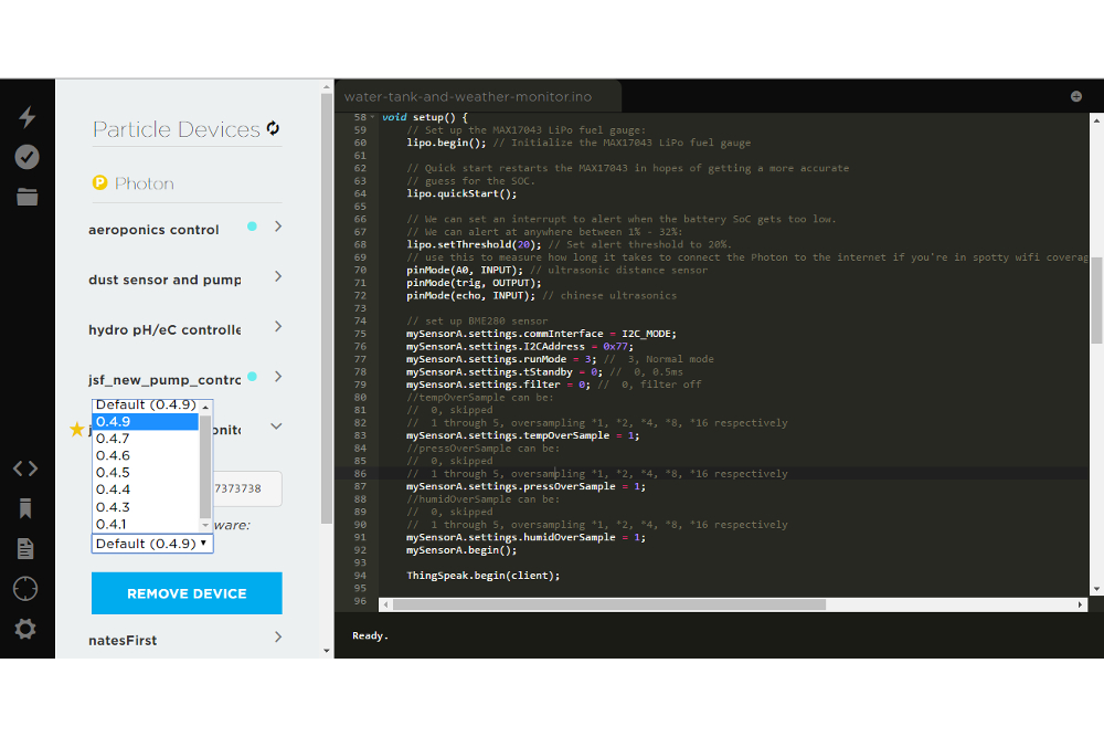
There are a few challenges when working with the Photon and its development environment. One of the biggest problems is that sometimes new firmware versions break old code. For example, from the time I developed this original system (Oct 2015) to the time this tutorial was written (Mar 2016), a new firmware version came out (0.4.9), which is incompatible with my old code. The worst part about it is, the Photon sits there blinking a red error message on the LED and is impossible to flash without physically accessing the device. Kind of a pain when it's on top of a roof and in a watertight enclosure held together by 6 screws (and there's a bunch of melting snow everywhere).
I think what ended up being broken with the new firmware was the WiFi.selectAntenna() function, which was silly and tiny. Regardless, we want to disable automatic firmware updates for our devices running important tasks like this, so it can keep running for years. To do this, click the 'Devices' icon on the left of build.particle.io, click the star (left) and the arrow (right) next to the device we're going to flash, then choose the 0.4.9 firmware (without Default). Re-flash your device, and it's good to go. Do this for both the telemetry and control box Photons.
Setting Up the ThingSpeak Channels
The Telemetry Channel
There are many sites out there for storing your IoT data. Here are two: dweet.io and my personal favorite, The Mathworks' ThingSpeak. ThingSpeak already has some nice built-in features, like Google visualization plugins, Twitter interfacing, React (which can do something like post a tweet when data meets a threshhold), MATLAB analysis, and more. It's also open-source.
First, sign up for a ThingSpeak account if you don't already have one. Next, create a channel by going to Channels->My Channels->New Channel. Click the checkboxes next to each field (1 through 8) and label them:
- Water Height (inches)
- P (inHg)
- pressure change rate (inHg/min)*10^6
- T (F)
- RH %
- light intensity
- battery V
- battery SOC
Check the box next to 'Make Public' if you want other people to be able to view it without needing the read API key. To finish, click 'Save Channel'.
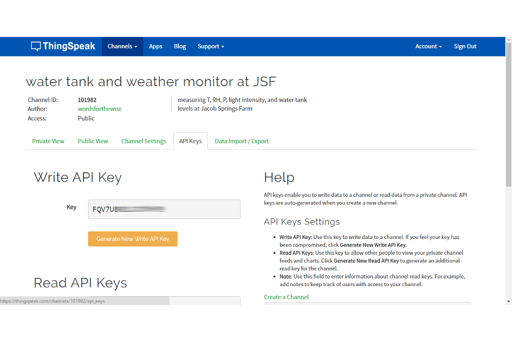
Now, click "API Keys" in the menu bar that should be around the middle of your screen. Copy the "Write API" key, and put that in your Photon telemetry box code as the myWriteAPIKey variable. Also copy the "Channel ID" number from your ThingSpeak channel page, and set that as the myChannelNumber variable in your Photon telemetry code.
Once you power up your telemetry Photon, you should see the data start getting populated (your ThingSpeak page will auto-refresh every 15-ish seconds).
Now, we'll set up a Twitter feed to post info on our data, which can be used to send alerts on rapidly dropping pressure (which can signal bad weather). Create a Twitter account, sign in, and go back to your ThingSpeak page. Click on "Apps" on the top menu bar. Click "ThingTweet", and then "Link Twitter Account".
Once you've linked your Twitter account, go back to the 'Apps' page and click on MATLAB analysis. Use this code, changing the API keys and channel ID for your channel:
language:MATLAB
% Calcuclates the pressure difference over the last 3 hours
% writes to channel as long as the time difference between
% the two points is at least 2 hours

% Channel ID to read data from
ChannelID = 101982;
% Pressure Field IDs
PressureFieldID = 2;
PressureChangeID = 3;

% TODO - Put your API keys here:
writeAPIKey = 'your write API key';
readAPIKey = 'your read API key'; % this is only necessary if the channel is private

% Get humidity data for the last 60 minutes from the MathWorks Weather
% Station Channel. Learn more about the THINGSPEAKREAD function by going to
% the Documentation tab on the right side pane of this page.

[pressure, timestamps, chInfo] = thingSpeakRead(ChannelID, 'ReadKey', readAPIKey,  'Fields', PressureFieldID, 'NumMinutes', 180);

[m,n]=size(pressure)
display(m)

if m > 1 % we need at least 2 points to do the calculation
    % Calculate the pressure change
    pressureChange = pressure(end)-pressure([1]);
    % pressure(end) gets us the most recent pressure reading, which is last in the pressure variable (a Matlab matrix)
    display(pressureChange, 'pressure change (inHg)'); % this shows up below when you hit run
    timeDiff = minutes(diff([timestamps([1]), timestamps(end)])); % difference in minutes between the first and last readings
    display(timeDiff);
    pressureChangeRate = pressureChange/timeDiff * 1000000;
    display(pressureChangeRate, 'pressure change rate (inHg/min)*10^6');


    % Write the average humidity to another channel specified by the
    % 'writeChannelID' variable

    % Learn more about the THINGSPEAKWRITE function by going to the Documentation tab on
    % the right side pane of this page.
    if timeDiff > 60.0 % make sure the time difference is at least 1 hour between the points
        for n=1:8 % quite a bit of a hack, but it works
            pause(2); % they don't allow more than 2s pauses (delays) here, and I didn't take the time
            % to figure out how to do a callback, etc
        end
        thingSpeakWrite(ChannelID, pressureChangeRate, 'Fields', PressureChangeID, 'writekey', writeAPIKey);
        display('writing to channel')
    end
else
    display('not enough data in channel yet')
end
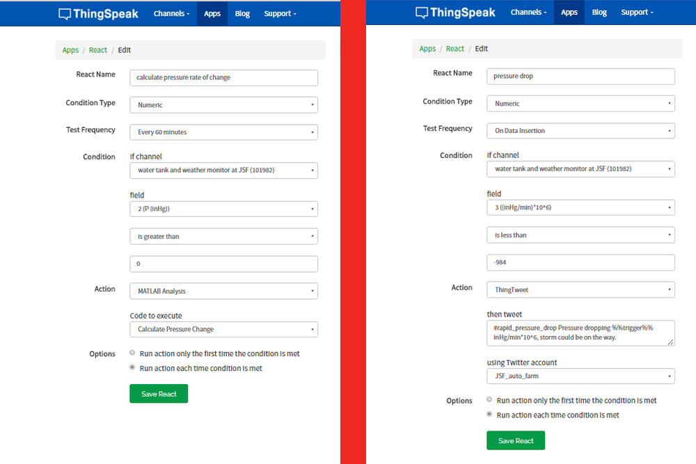
Make sure to hit 'save and run', and you can check the output below the code area to see it working. Scroll down a bit, click "React", then set up a react to run on new data insertion. The picture below shows the details for the react, which are:
| Option name | Value |
|---|---|
| React name | calculate pressure rate of change |
| Condition type | Numeric |
| Test frequency | On Data Insertion |
| Condition: If channel | (your telemetry channel name) |
| Condition | field: 2 (P (inHg)); Is greater than; 0 |
| Action | MATLAB analysis |
| Code to execute | Calculate Pressure Change |
| Options | Run each time condition is met |
Finally, go back to 'Apps' one more time to set up some Twitter alerts. Click on 'React' and then 'New React'. Set the values as shown in the picture above, and the table below:
| Option name | Value |
|---|---|
| React name | pressure drop |
| Condition type | Numeric |
| Test frequency | On every 60 minutes |
| Condition: If channel | (your telemetry channel name) |
| Condition | field: 3 (pressure change rate (inHg/min*10^6); Is greater than; 984 |
| Action | ThingTweet |
| then tweet | #rapid_pressure_drop Pressure dropping %%trigger%% inHg/min*10^6, storm could be on the way. |
| Using Twitter account | (your twitter account here) | Options | Run each time condition is met |
The %%trigger%% is replaced by the value of the field. Hit 'Save React,' and you're good to go.
The Control Box Channel
Set up another ThingSpeak channel, with just two fields set as:
- pump on
- motion detected
The API keys from this will be used in the control box Photon code.
ThingSpeak Google Gauges
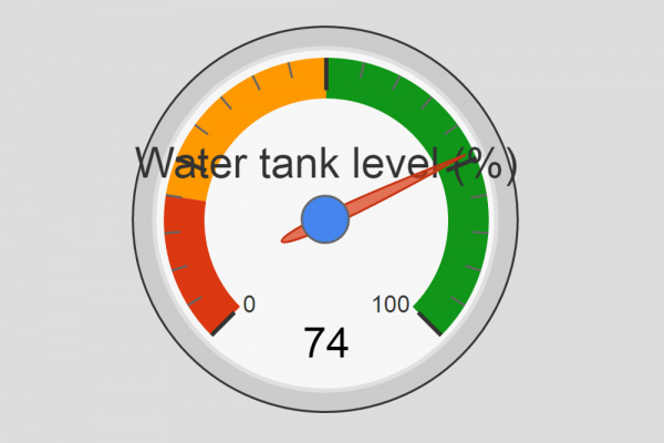
Another nice feature of ThingSpeak is the ease with which nice looking graphics can be made (once you get the hang of it). For example, a Google Gauge can be embedded in your ThingSpeak channel (or anywhere else with JavaScript). Unfortunately, ThingSpeak recently disabled JavaScript apps from being on public pages, so this will only work on private views or other custom applications.
To get this gauge going for the water tank fullness, go to ThingSpeak.com, click Apps->Plugins->New->Google Gauge->Create, and use this code for the JavaScript:
language:javascript
<script type='text/javascript' src='https://ajax.googleapis.com/ajax/libs/jquery/1.9.1/jquery.min.js'></script>
<script type='text/javascript' src='https://www.google.com/jsapi'></script>
<script type='text/javascript'>

  // set your channel id here
  var channel_id = channel ID here; // eg 101992
  // set your channel's read api key here
  var api_key = 'your readAPI key here';
  // maximum value for the gauge
  var max_gauge_value = 42; // this is the maximum water height from your telemetry code
  // name of the gauge
  var gauge_name = 'Water tank level (%)';

  // global variables
  var chart, charts, data;

  // load the google gauge visualization
  google.load('visualization', '1', {packages:['gauge']});
  google.setOnLoadCallback(initChart);

  // display the data
  function displayData(point) {
    data.setValue(0, 0, gauge_name);
    data.setValue(0, 1, point);
    chart.draw(data, options);
  }

  // load the data
  function loadData() {
    // variable for the data point
    var p;

    // get the data from thingspeak
    $.getJSON('https://api.thingspeak.com/channels/' + channel_id + '/feed/last.json?api_key=' + api_key, function(data) {

      // get the data point
      p = data.field1;

      // if there is a data point display it
      if (p) {
        p = Math.round((p / max_gauge_value) * 100);
        displayData(p);
      }

    });
  }

  // initialize the chart
  function initChart() {

    data = new google.visualization.DataTable();
    data.addColumn('string', 'Label');
    data.addColumn('number', 'Value');
    data.addRows(1);

    chart = new google.visualization.Gauge(document.getElementById('gauge_div'));
    options = {width: 200, height: 200, redFrom: 0, redTo: 20, yellowFrom:20, yellowTo: 50, greenFrom: 50, greenTo: 100, minorTicks: 5}; // customize the red, yellow, and green levels if you want

    loadData();

    // load new data every 15 seconds
    setInterval('loadData()', 15000);
  }

</script>
Don't forget to change the \<title> in the HTML section. Then simply click checkboxes on the channels for which you want the Gauge to be visible. You can drag and drop the Gauge (while viewing the channel) to be anywhere on the page.
Setting Up Text Alerts
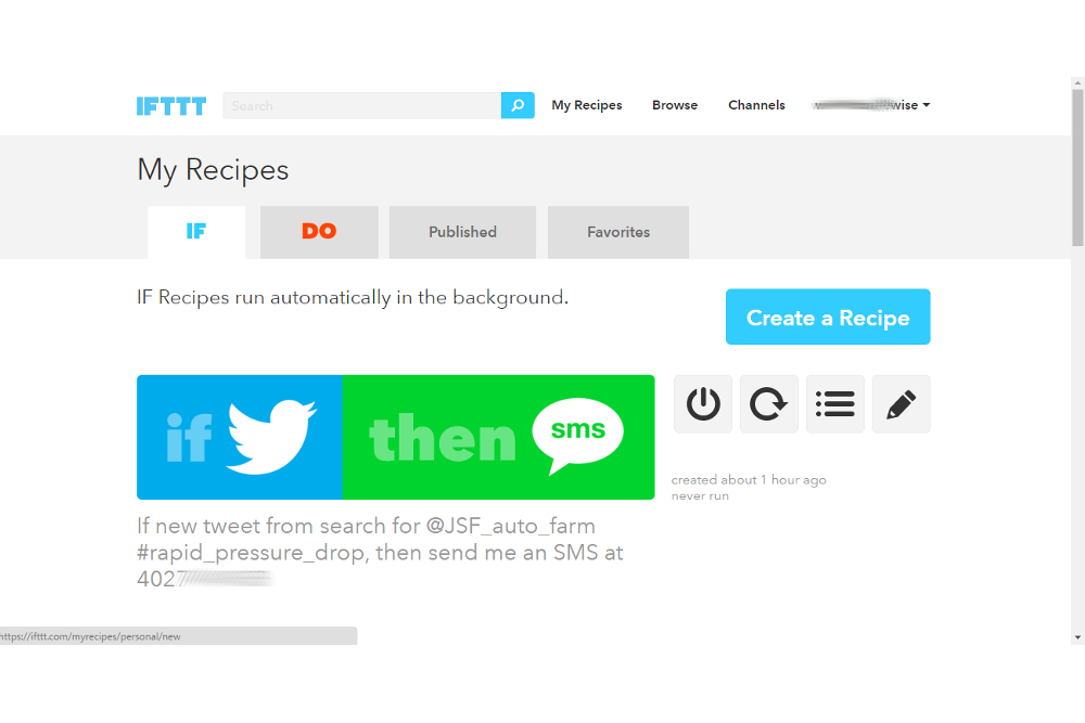
If you want to get an alert via text or email when the pressure drops rapidly (or for other data events), it can be done with ifttt.com. Head over there and setup an account, and connect your phone to IFTTT. Click 'My Recipes' on the top menu, click 'Create a Recipe', then click 'this'. Search for 'twitter,' and click on the Twitter icon. Unfortunately, IFTTT's "tweet from search" feature seems to be broken, hopefully it's fixed soon. For now, the best we can do is send a text every time we post a new tweet. This unfortunately means we can't tweet more mundane things right now, since it would be annoying getting that many texts.
Click 'New tweet by a specific user', then enter your username after the "@" symbol, similar to "@JSF_auto_farm". Next, click 'that', search for SMS, and click 'Send an SMS'. I just left the message as the default. Click 'Create Action' and 'Create Recipe', and that's it! If you had to create and link accounts for everything to get to this point, it will be much faster next time you want a text alert for some remote measurement.
When IFTTT does eventually get their Twitter search feature fixed, we can use a hashtag to filter our results. After clicking 'this', search for 'twitter', then choose 'New tweet from search'. Use this as the search:
"@your_twitter_username" "#rapid_pressure_drop"
replacing your_twitter_username with the one you picked previously.
Alternate: Use Gmail to Send Texts
For the 'that' portion, you can also choose Gmail (you will have to link a Gmail account for this step), and click 'Send an email'. If you want to send a text, you can do it as so:
1234567890@vtext.com
Instructions for using email to send a text with any carrier can be found here. I was having trouble getting the texts to consistently go through via Gmail with IFTTT, so I switched to the straight IFTTT SMS feature.
There are many other ways to set up SMS alerts, such as Twilio, [SendGrid](https://sendgrid.com/marketing/sendgrid-services?cvosrc=PPC.Google.sendgrid&cvo_cid=SendGrid%20-%20US%20-%20Brand%20-%20(English)&mc=Paid%20Search&mcd=AdWords&keyword=sendgrid&network=g&matchtype=e&mobile=&content=&search=1&gclid=Cj0KEQjw5ti3BRD89aDFnb3SxPcBEiQAssnp0vQjWtm5suVbWc1LH1ttqbI4AjmB6nc5-v0L3T5GgocaAp6A8P8HAQ), or IOBridge. None of these methods have been tested with this setup yet.
Final Data Analysis
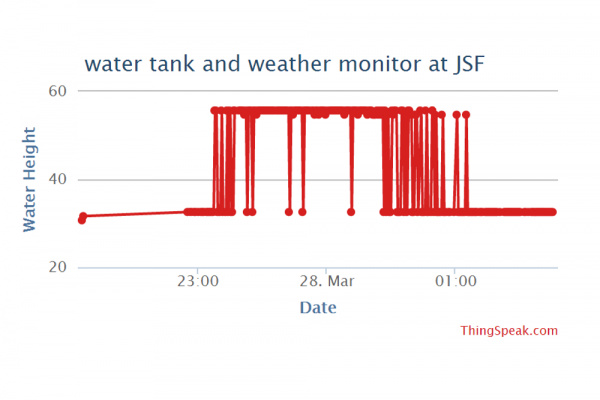
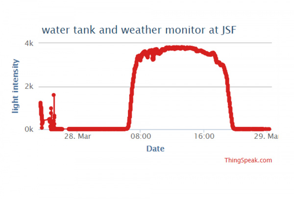
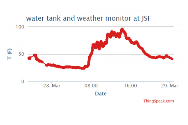
Here's some data from field testing:
Resources and Going Further
For better system reliability (to keep running during Internet outages) you could run the particle cloud locally (which would require more processing to log data on ThingSpeak), use long-range serial radio transceivers (like this one to communicate directly between the Photons), or eventually, just communicate directly between the photons. Don't forget you can use long-range antennas like yagi antennas to boost your connection range.
If you want to take this further, you can always:
- use an Photon Internet button to remote control the pump
- build an aluminum light-shield (with a hole for the photocell) to keep the box from getting too hot in the summer
- log the humidity and temperature in the tank using this sensor (or others)
- log the water temperature with a sensor
- log water pressure near the pump with a sensor
- log water flow rates with a flowmeters
- alerts for too high or low of temperature (ideal charging temperatures are 32-113 F, and the electrolyte in the batteries starts to decompose at about 160 F) -- if you're in the desert, you might want to get a text if the box is getting hot so you can cover it with a wet shadecloth, or permanantly shade the box with aluminum
- analysis of pump flowrate/water usage using MATLAB processing in ThingSpeak
- analysis of energy use/pump on time with MATLAB processing
- analysis of pump hours run, and alerts when it's time for maintenance or nearing the pump's end-of-life
- uptime of photons
- motion sensor alarms late at night with ThingSpeak reacts
- web interface for controlling the pump
- remote control button for pump control
- remote monitoring in the house, etc (OLED, TFT, WS2812 LEDs) for telemetry data
I've already created a simple web form that can be used to remotely control the pump, and switch it between manual and auto mode, but it requires a little more coding of the Photons, and serving a web page. Perhaps in a future tutorial I'll show you how to do these things.
Again, all the code for this project can be found on GitHub.
For more Photon fun, check out these other great SparkFun tutorials:
