Photon Remote Water Level Sensor
Build the Pump Controller
The contactor/relay idea is used here to control a pump for a well, but could also be used to control a solenoid for a sprinkler/watering system (you'd probably only need a relay in that case), or to switch on lights, motors, or pumps in a structure (greenhouse, warehouse, etc), heavy-duty heaters, or other remote control needs you might have.
Triacs, Contactors, and Relays -- Oh My
To begin, let's discuss the various ways to control AC power.
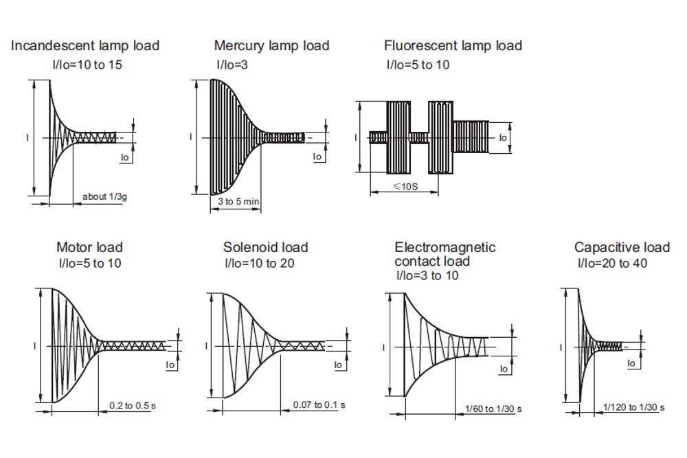
To switch lighter, resistive AC loads (like a small electric heater), a relay can be used. However, once you need to switch a pump on or off, or another inductive load, a different kind of switch is usually needed. Why? It's because when inductive loads start up, they exert a huge load--but only temporarily. See this stackexchange question. Using an undersized relay with an inductive load like a pump can be a dangerous proposition; the heat from the start up of an inductive load could eventually fuse the relay contacts together, leaving your pump constantly on and you not even knowing it.
A triac is another way to control AC with silent operation, though I won't go into any details as this project didn't use any.
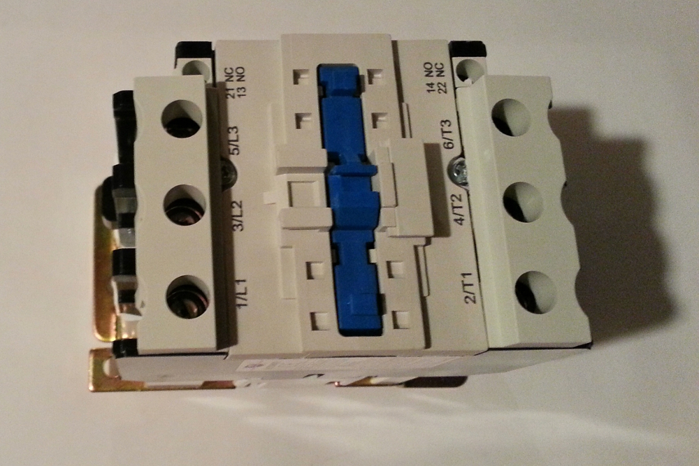
For a beefy motor, like a well pump or other industrial sized applications (like turning on the lights in an entire warehouse, etc), you want to use a contactor. These are rated by [UL](https://en.wikipedia.org/wiki/UL_(safety_organization)) for certain motor loads, like 1 hp (~750 W), 2 hp (~1500 W), etc. In our case, we have a motor that I measured at 1500 W -- about 2 hp. Oversizing electrical components is usually the safest bet, so I picked a 3 hp contactor from US Breaker Inc., which had some of the best prices I could find. The datasheet tells us it can handle 3 hp at 120 V. The coil, which controls the contactor, takes about 2 A at startup and about 0.2 A thereafter, so a 10 A relay is more than enough to handle this, plus we can then easily control this from a MCU. The coil runs off of straight-up 120 V, so we don't need another power supply to control the contactor, just a relay that can switch up to 2 A at 120 V.
The breaker is rated for 800,000 cycles, which should last about 91 years if the breaker is switched every hour (and it will probably be switched much less often). US Breaker has [other contactors that can handle up to 7.5 hp inductive loads (5600 W) at 120 V](https://www.usbreaker.com/miva/merchant.mvc?Screen=SRCH&Store_Code=UBI&Search=%22Chint%20NC1(Contactor)%20Family%22) in case you need more beef.
Electrical Setup
If you're new to soldering check out this tutorial and practice on some scrap parts before trying the real thing. Solder the relay together, if you're using the SparkFun Kit. You can find assembly instructions for the relay kit in this hookup guide.
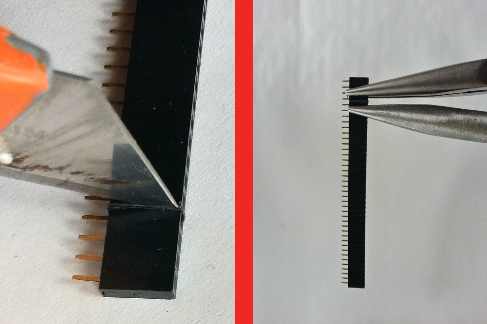
Cut 2 sets of female headers to the correct size (20 units) by first scoring with an exacto knife (I do it on all sides of the headers), then use two pairs of needle-nosed pliers to make a clean break. Score each side a few times to get a deep cut. It will probably take you a few tries to get the hang of it, so don't get discouraged when the first few don't work out.
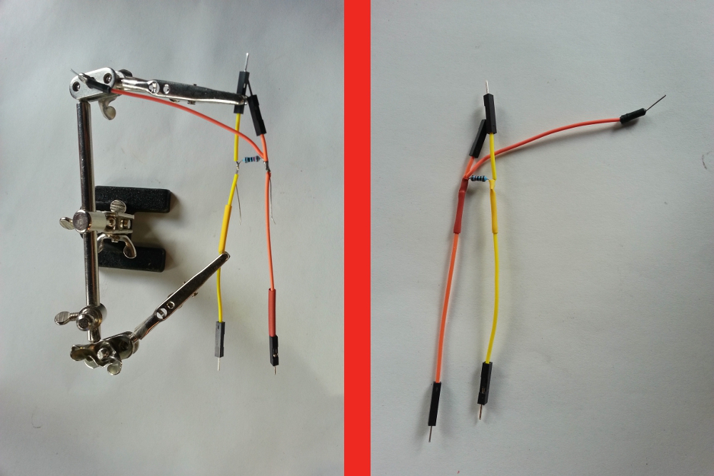
Assemble 3 male-to-male jumpers into a connector for the PIR and relay. There should be a 10kΩ resistor between the 5V (Vin) and dataline for the PIR. The 5V line should be split, one to go to the relay and one to the PIR. Before soldering things together, put some heatshrink on the wires so it is easy to cover up bare wires. After soldering, heat the heatshrink with the heat gun until they tightly grip the wires (don't heat for more than 5-8 seconds).
Solder the headers to the ProtoShield. Solder the PIR data header to the D7 hole, the Vcc header to the Vin hole, and the GND header to one of the GND holes. Solder another jumper to the other GND hole and one more jumper to the D0 hole for the relay.
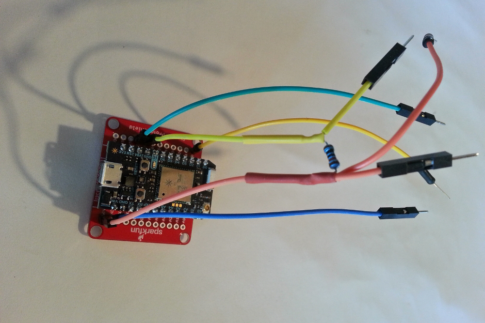
Next, test the relay and contactor to make sure everyone's riding on the gravy train. Connect the GND, Vin, and D0 jumpers to the GND, 5V, and CTRL of the relay board, respectively. Upload the code below (via build.particle.io) to your Photon to test the relay (listen for the clicking every few seconds to make sure it works and watch the LED. You can also test the resistance between the 'load' and 'normally open' screw terminals on the relay to make sure it goes between 0 and infinity if you wish.
language:c
void setup() {
    pinMode(0, OUTPUT);
}

void loop() {
    digitalWrite(0, HIGH);
    delay(2000);
    digitalWrite(0, LOW);
    delay(2000);
}
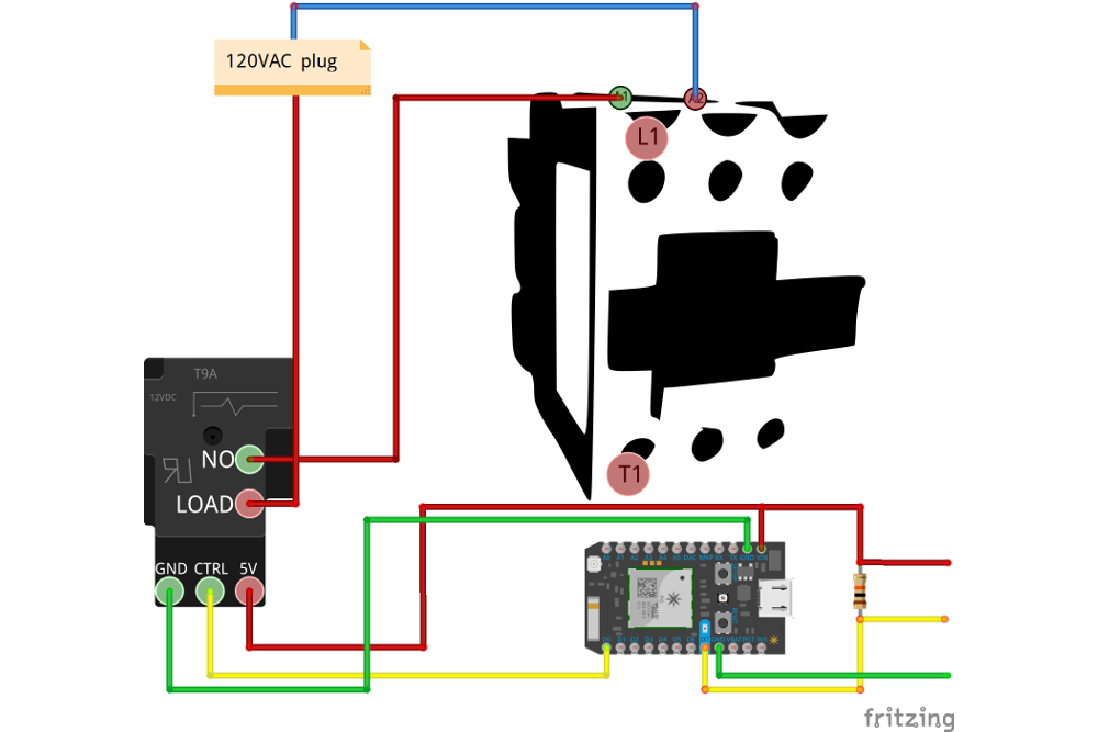
Next is the contactor. Hook up some wire from an AC plug to the relay terminal, then from the other relay terminal to the contactor A1 connector, and last the other end of the AC wire to the contactor A2 terminal. Run the relay test again and make sure the contactor is switching. You will definitely notice when the contactor is working, as it clicks on and off with authoritah. You can again use a multimeter to watch the resistance between some of the 'T' and 'L' terminals if you wish; it should drop from 1 to 0 when the relay is on.
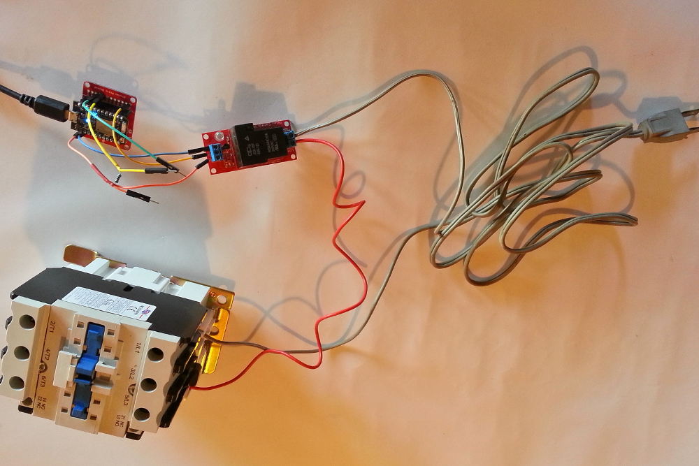
Not surprisingly, the beefy contactor is much louder than the relatively cutesy little relay.
Connect the PIR sensor to the Photon: connect the D7 jumper to the signal line (black wire), the Vin to the red wire, and the white wire to GND. There's a tutorial here explaining more about this sensor, but it's pretty simple -- when motion is detected, the output pin from the sensor pulls low. Power up the Photon, and upload this code:
language:c
void setup() {
    pinMode(7, INPUT);
}

void loop() {
    int pirVal = digitalRead(7);
    if(pirVal == LOW){
        Serial.println("Motion Detected");
        delay(2000);
    }
}
Check to make sure the PIR sets off the alarm when you wave your hand in front of it. You can tell if it's working because the D7 LED will light up when the alarm is triggered. Additionally, you can type 'particle serial monitor' in your terminal/command console (with the Photon plugged into your computer via USB) to watch the serial output from the device, which should print 'Motion Detected' when you wave your hand in front of it.
Physical Construction
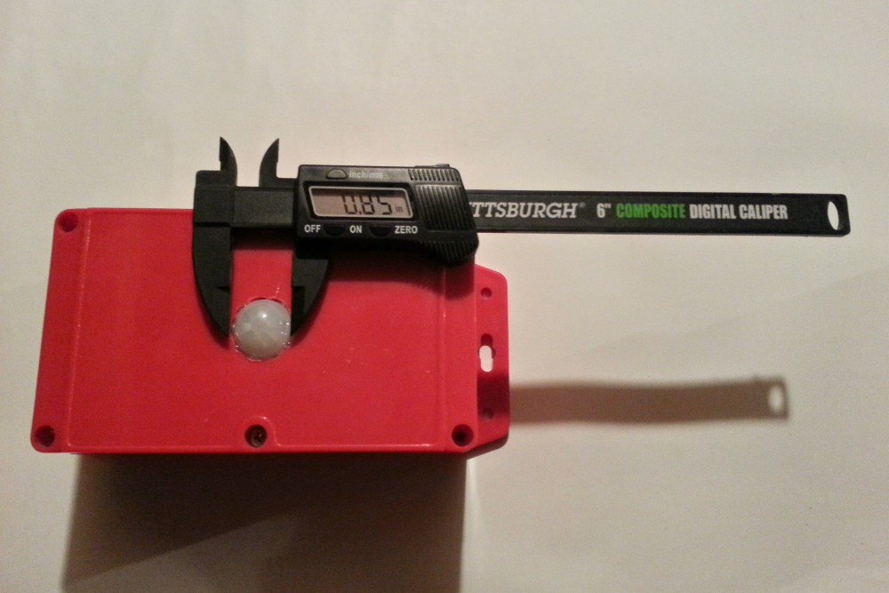
First, drill a hole in the front of the case for the PIR sensor. The PIR sensor used here has a diameter of about 0.85", or 21.5 mm, so I used a 3/4" drill bit and widened the hole with the 1/2" drill bit. I hot-glued the PIR in there. Add some hot glue on the corners of the board to hold it to the red box. For a more secure job, drill holes, and use 2mm screws and nuts to secure the board to the case.
Next, drill a 1/2" hole in the side of the case. Drill some 1/8" holes for mounting the ProtoShield and relay, if you want to secure the board with 6-32 screws or a similar size. For ease and quickness, I just hotglued the boards to the box.
String the 5V power supply cord through the 1/2" hole we drilled in the side of the enclosure, and plug the micro-USB power cord into the Photon. If you want to be more professional, use a PG-7 cable gland to string the wires through. Attach some wires to the relay, leaving enough length to connect to the AC leads in your field installation (I used 18-gauge wire, since this will only be carrying about 0.2A at steady-state). If you drilled mounting holes for the relay and protoboard earlier, secure the boards using screws. Otherwise, use a hot glue gun to attach the boards to the case. Finally, hot glue the wires through the hole for strain relief and to prevent pull-out of the wires from the relay.
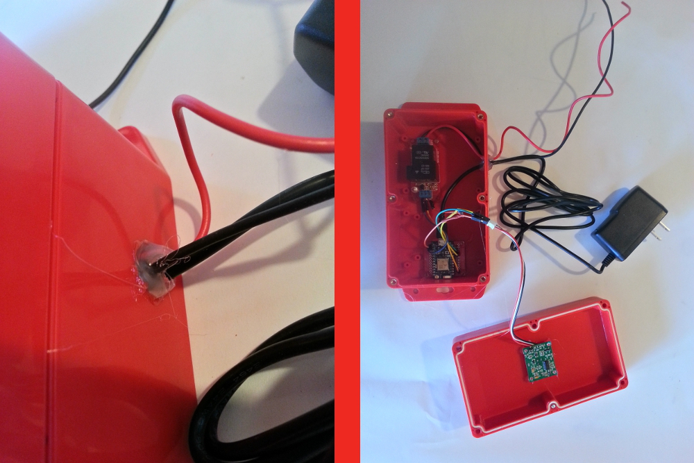
Finally, screw the box together with the six screws on top.
Field Installation
Use some screws to attach the box to a wall near your pump and AC leads and some screws as mounting for the contactor, if you're not going with a DIN rail. I used some extra screws we had laying around, they seem like #8 1-1/4" drywall screws, and I drilled shallow 1/8" pilot holes before screwing them in.
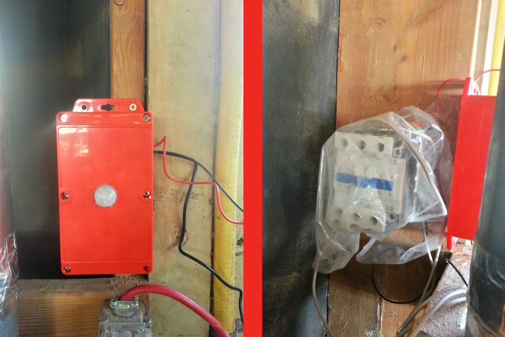
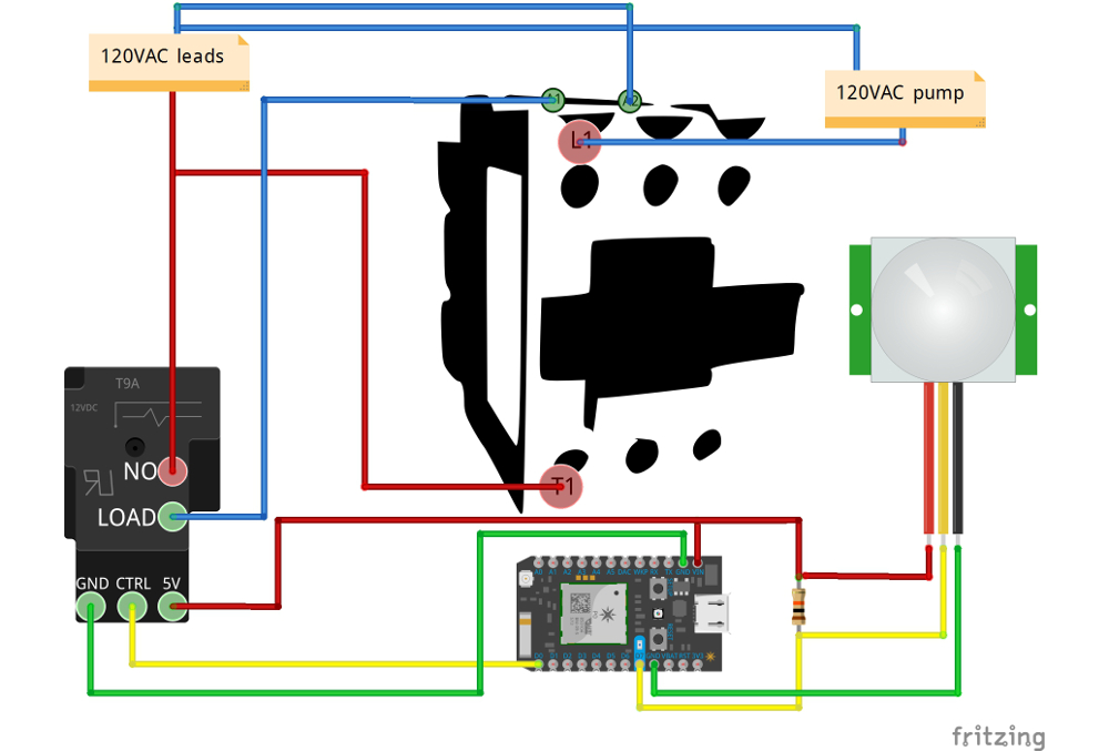
Once the contactor screws are in, hang the contactor on them, and tighten the screws so that the contactor won't be rattling around much. Take the contactor back off, attach your wires to the terminals L1, T1, A1, A2, and the GND terminal (you will ideally want a small bolt/nut for this GND connection, seems like 6-32 with ½" length would work). If you're going to be in a dusty area (for example, we're in a wood shop) use protection and cover the contactor with plastic, etc. Finally, hook up the wires correctly to the pump and power cord, as shown in the full circuit diagram below.
Run the relay test program from earlier to verify everything is working.
We'll come back to data collection and automation of the pump control after installing the remote sensor.