LED Cloud-Connected Cloud
Contributors:
 Sarah Al-Mutlaq
Sarah Al-Mutlaq 
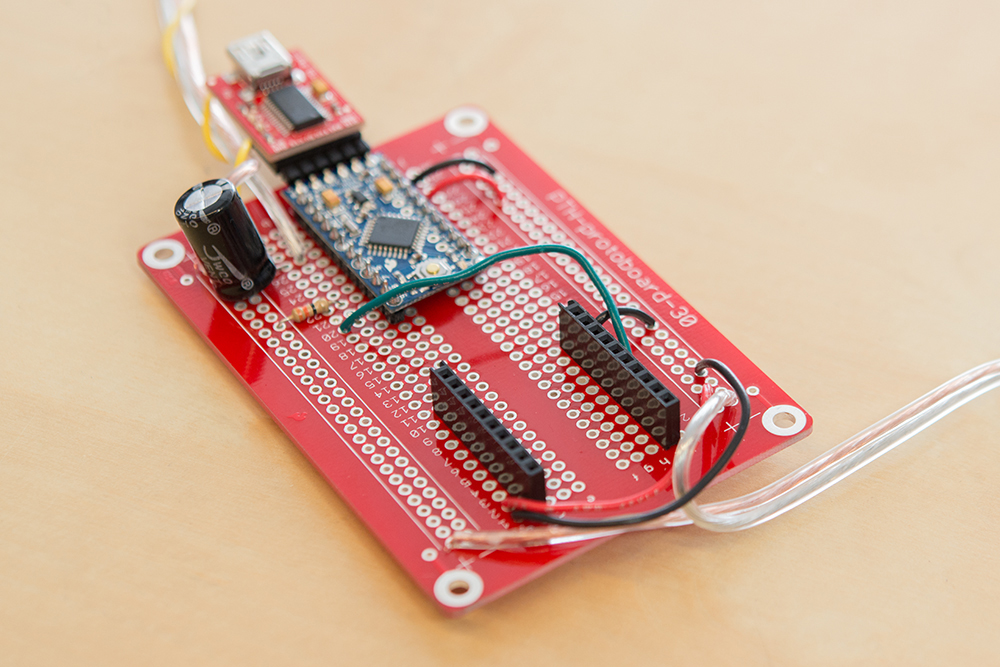
Electronics Assembly Part 2
This section will cover adding a SparkFun thing to your project so that it can connect to the Internet.
You can keep all the soldering done in part 1, but just add a SparkFun Thing board to allow for use with your phone as well as to pull weather data.
Connect the components as follows:
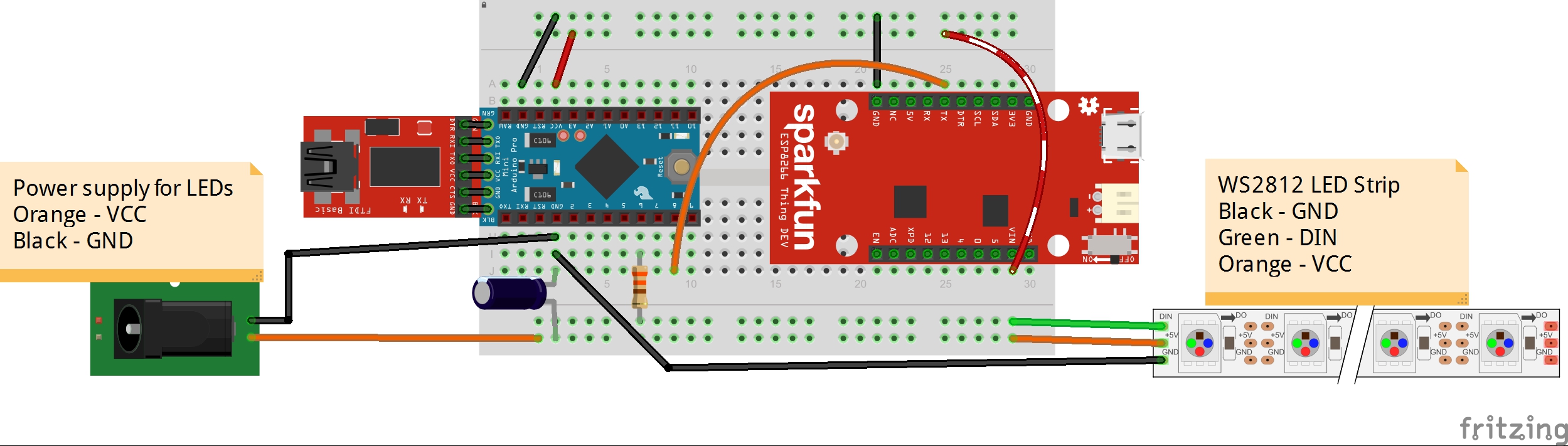
Click the image for a closer look.
| Component | Breadboard | |||
|---|---|---|---|---|
| Resistor | a22 (Pro Mini Pin 6) | Bottom - (LED Strip DIN) | ||
| Capacitor | a27 (Pro Mini GND Pin) | Bottom + (LED VCC) | ||
| Jumper Wire | Top - (GND) | i29 (Pro Mini GND Pin) | ||
| Jumper Wire | Top + (Board VCC) | i27 (Pro Mini VCC Pin) | ||
| Jumper Wire | b25 (Pro Mini Pin 3) | f15 (button) | ||
| Jumper Wire | f13 (button) | Top - (GND) | ||
| Jumper Wire | a20 (Pro Mini Pin 8) | j7 (SparkFun Thing Pin TX) | ||
| Jumper Wire | j10 (SparkFun Thing GND Pin) | Top - (GND) | ||
| Jumper Wire | a2 (SparkFun Thing VIN Pin) | Top + (Board VCC) | ||
| Wire | b27 (Pro Mini GND Pin) | Ground of barrel jack | ||
| Wire | Bottom + (LED VCC) | VCC of barrel jack | ||
| Wire | c27 (Pro Mini/LED power GND Pin) | Yellow wire on LED strip (LED GND) | ||
| Wire | Bottom - (To Pro Mini Pin 6) | Green wire on LED strip (DIN) | ||
| Wire | Bottom + (LED power VCC) | Red wire on LED strip (LED VCC) | ||
* Pins not listed are not used.
Again, same notes as part 1: adding a capacitor and resistor, and powering the Pro Mini and Thing from the wall (read part 1 for all the details).
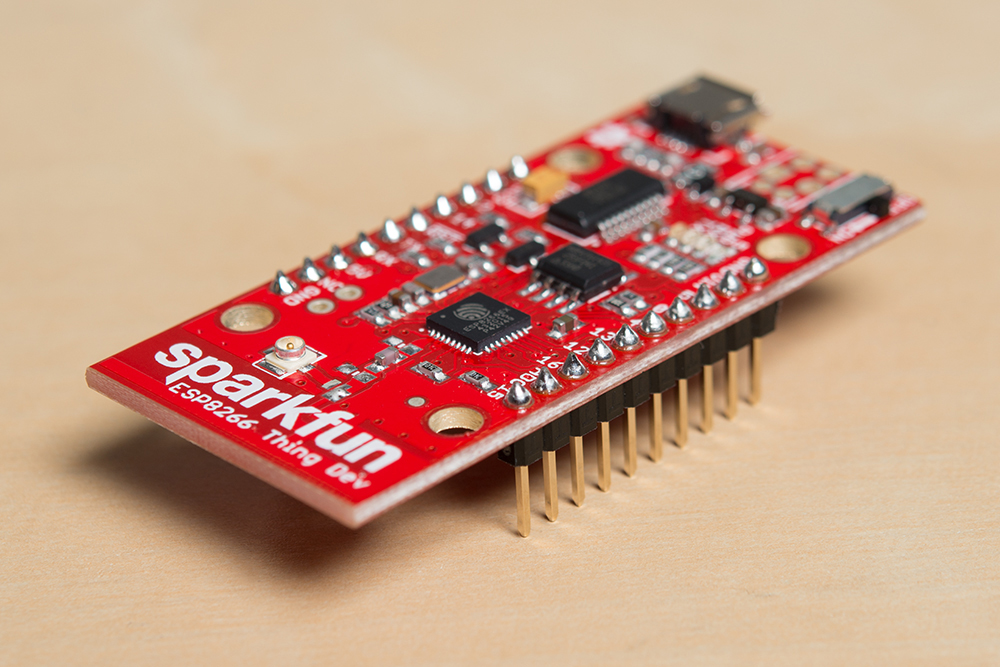
One additional note, for ease of programming both the Pro Mini and the SparkFun Thing board, you may want to solder in female headers where the Thing board will sit and male headers to the Thing board, so that you can easily take it out to program both.