LED Cloud-Connected Cloud
Electronics Assembly Part 1
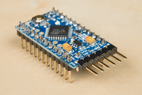
This section will cover building the Pro Mini Circuit. We will add the Internet-connected portion in Part 2.
Connect the components as follows:
Please note that we are soldering all these components to a solderable breadboard. Feel free to build the circuit on a breadboard first to test everything out.
| Component | Breadboard | |||
|---|---|---|---|---|
| Button | j17 (To Pro Mini Pin 3) | g15 (GND) | ||
| Resistor | a22 (Pro Mini Pin 6) | Bottom - (LED Strip DIN) | ||
| Capacitor | a27 (Pro Mini GND Pin) | Bottom + (LED VCC) | ||
| Jumper Wire | Top - (GND) | i29 (Pro Mini GND Pin) | ||
| Jumper Wire | Top + | i27 (Pro Mini VCC Pin) | ||
| Jumper Wire | b25 (Pro Mini Pin 3) | f15 (button) | ||
| Jumper Wire | f13 (button) | Top - (GND) | ||
| Wire | b27 (Pro Mini GND Pin) | Ground of barrel jack | ||
| Wire | Bottom + (LED VCC) | VCC of barrel jack | ||
| Wire | c27 (Pro Mini/LED power GND Pin) | Yellow wire on LED strip (LED GND) | ||
| Wire | Bottom - (To Pro Mini Pin 6) | Green wire on LED strip (DIN) | ||
| Wire | Bottom + (LED power VCC) | Red wire on LED strip (LED VCC) | ||
* Pins not listed are not used.
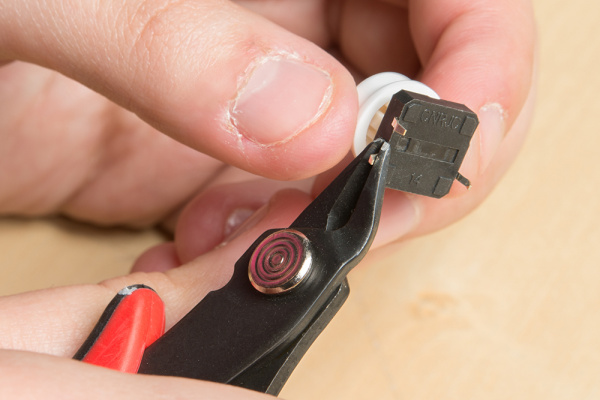
Take a button, and cut off two legs that are diagonal to each other so that it doesn't cause a short circuit.
Some things to note here is that I have put a 1000 microfarad capacitor between the LED power and ground. This is good practice, and helps distribute the current better, so that you don’t accidentally blow out your first LED. This should be done on any string of wires as a precautionary measure. I have also placed a 330Ω resistor between the DIN of the LEDs and the microcontroller. This is another good measure to protect the addressable LEDs.
The Pro Mini will need to be powered separately from the LEDs, and this can be done through the Mini USB port of an FTDI Basic. (If you don’t want it to run off your computer you can get this USB wall charger). You can also solder wires directly to the Pro Mini's VIN pin.


