IR Control Kit Hookup Guide
 jimblom,
  bboyho
 Introduction
Infrared (IR) is a cheap and (as you'll soon discover) easy way to add wireless control to your project. The IR Control Kit gives you everything you need to take control of the extravisible light waves (or are they particles?), so you can remotely control your custom music box or build a controller for your TV or stereo.
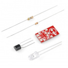
In this tutorial we'll show you how to hook up all of the components included with the IR Control Kit, which includes:
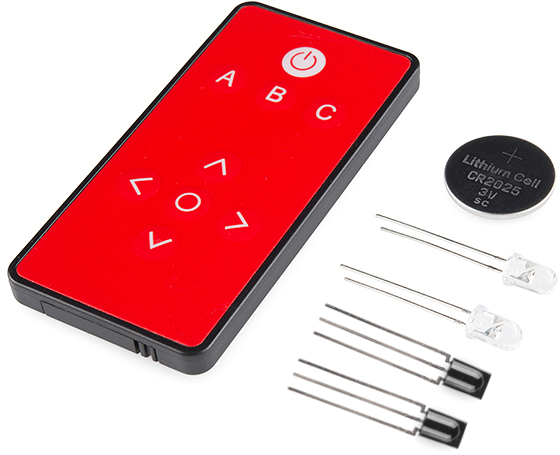
- SparkFun's custom-made Infrared Remote Control
- A CR2025 Coin Cell Battery for the remote.
- Two 38kHz demodulating Infrared Receiver Modules
- Two 950nm-emitting Infrared LEDs
- A handful of 330Ω resistors. You can never have enough current-limiting resistors.
Required Materials
In this tutorial, we'll be using an Arduino to both transmit and interpret received IR data. On top of the components included with the IR Control Kit, you'll also need these to follow along with this tutorial:
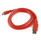
- An Arduino (or Arduino-compatible board) and a means to program it.
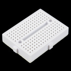
- A breadboard is optional but recommended to help with the hardware hookup.
- As with the breadboard, jumper wires are optional but the recommended tool to wire between breadboard and Arduino.
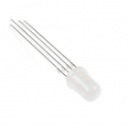
- The second of the examples uses a common cathode RGB LED to create a fun, IR-controlled RGB LED project. This is optional.
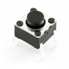
- The third example uses a simple momentary push-button to trigger an IR code transmission. Optional again.


Suggested Reading
If you aren't familiar with the following concepts, we recommend checking out these tutorials before continuing.
Light
IR Communication
What is an Arduino?
Button and Switch Basics
Light-Emitting Diodes (LEDs)
Serial Terminal Basics
Hardware Overview
Before we dig into wiring stuff up and uploading sketches, let's quickly overview each of the components in the IR Control Kit.
IR LED
Let's start with simplest of the components first -- the infrared LED. Anyone who's ever worked with electronics has blinked an LED, but those blinking LEDs are usually in our visual spectrum. These IR LEDs are just like any LED you've blinked before, but they emit light at a wavelength of about 950nm -- radiation well outside of our visual range (about 390 to 700nm).
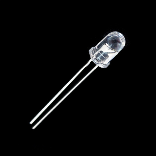
You can't see these LEDs light up, but you can still use them just like any LED. They still have two polarized legs: an anode (positive, the long leg) and a cathode. They have a typical forward voltage of about 1.5V, and a maximum forward current of 50mA. For more specs, you can check out the LED's datasheet.
330Ω Current Limiting Resistor
Just as with any LED, the IR LED needs a series resistor to limit current. That's what the included 330Ω resistors are for.
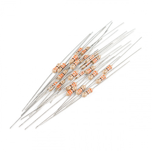
With a 5V supply connected to the resistor/LED series combo, current through the LED should be limited to about 10mA, which is well inside its safe operating range.
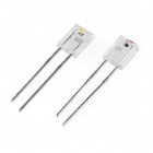
TSOP38238 IR Receiver Module
While it may look like a simple transistor, the TSOP38238 IR receiver module is actually a unique, light-demodulating integrated circuit.
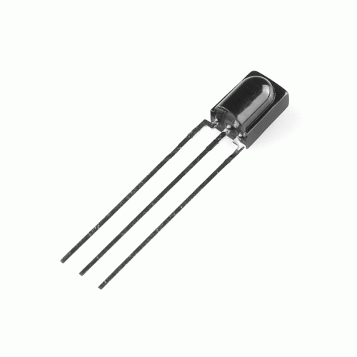
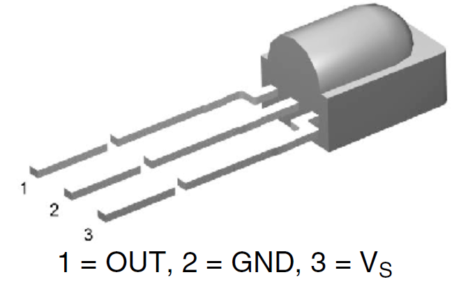
With three pins, it's about as simple as an IC can get. There are two pins for power -- ground in the middle, and VS to a side -- and one, single data output pin.
The IR receiver can be powered at anywhere from 2.5V to 5.5V, so it plays very nicely with a variety of development boards.
This module is tuned to demodulate 38kHz signals, which are a very common in the IR signal world. It turns a spiky, modulated signal (as shown on the image on the left) into this cleaner much easier to read signal (as shown in the image on the right):
 |
 |
So all we have to do to read the output of this device is count high and low pulses, and measure their durations. For more information on the TSOP38238, check out its datasheet.
IR Remote
Finally, we come to the flashy part of the kit: SparkFun's custom-made Infrared Remote Control.
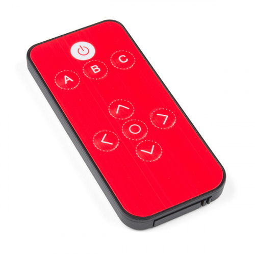
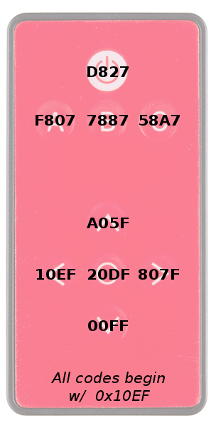
The nine button remote emits unique 32-bit codes for each button press. The codes are mapped as shown in the images below (this will come in handy in our first example). Depending on the IR remote that you are using, the values may be different.
 |
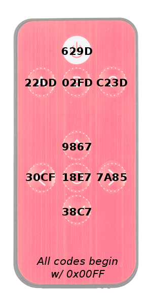 |
| Hex Codes for COM-11759 | Hex Codes for COM-14865 |
The remote's infrared output signal is modulated at 38kHz, so it works perfectly with the IR receiver module.
How to Battery?

The IR remote doesn't come with a battery installed but the IR Control Kit includes one for it. The battery compartment can be found on the bottom edge of the remote. To open the battery compartment, pinch the latch with your thumbnail while pushing the drawer out with another fingernail.
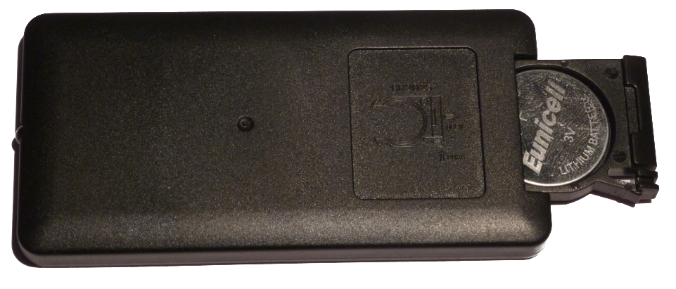
Insert the battery so that the positive (+) side is facing the bottom of the remote. Then slide the battery drawer back in.
Library Overview
Download and Install Ken Shirriff's IRremote Library
To quickly and easily add IR control to your Arduino, we recommend you download Ken Shirriff's IRremote library. Shirriff has written a library for IR remote. You can obtain this library through the Arduino Library Manager. Search for IRremote by shirriff and you should be able to install the latest version. If you prefer downloading the libraries manually you can grab them from the GitHub repository:
The IRremote library is a powerful tool for adding IR to your project. Whether you want to send IR codes out to an appliance, or transmit IR codes from a remote to your Arduino (or both!). We'll go over some of the simple stuff you can do with the library. For more help using it, check out Ken Shirriff's blog.
Example 1: IR Remote Control Values
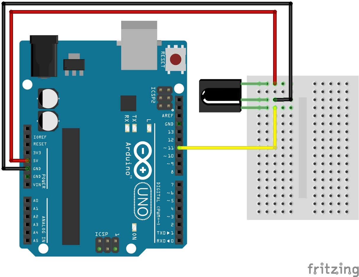
Circuit Diagram
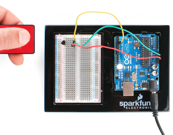
Ready to start hooking everything up? Check out the circuit diagram below to connect the components together.
Reading IR Remote Control Values
Copy and paste the below code into your Arduino IDE. Then upload it to your Arduino to view the values associated with each button.
language:c
/*
  SparkFun Electronics 2013
  Modified by: Ho Yun "Bobby" Chan on 8/6/2018
  Playing with Infrared Remote Control
  Description: By pressing on one of the SparkFun infrared remote
  control's buttons, the serial monitor will output the associated
  hex value when a signal is received by an IR receiver.

  If using with the IR Receiver Breakout (SEN-8554):
  Supply voltage of 2.5V to 5.5V
    Attach
    OUT: To pin 11 on Arduino
    GND: GND
    VCC: 5V

  If using with the IR Receiver Diode (SEN-10266):
  Supply voltage of 2.5V to 5.5V
    Attach
    OUT: To pin 11 on Arduino
    GND: GND
    VS: 5V

  Note: This is based on Ken Shirriff's code found on GitHub.
  Make sure to install the library:
  https://github.com/shirriff/Arduino-IRremote/

  Note: This code also works with cheap remotes. If you want to look
  at the individual timing of the bits, use this code:
  http://www.arduino.cc/playground/Code/InfraredReceivers
*/

#include <IRremote.h>

int RECV_PIN = 11;
IRrecv irrecv(RECV_PIN);
decode_results results;

//------------------------------------------------------------
//Codes for Infrared Remote Control
//COM-11759 https://www.sparkfun.com/products/retired/11759
//Note: Uncomment out this section if you are using this w/ the older remote.

/*
#define POWER 0x10EFD827
#define A 0x10EFF807
#define B 0x10EF7887
#define C 0x10EF58A7
#define UP 0x10EFA05F
#define DOWN 0x10EF00FF
#define LEFT 0x10EF10EF
#define RIGHT 0x10EF807F
#define SELECT 0x10EF20DF
*/
//------------------------------------------------------------
//Codes for Infrared Remote Control
//COM-14865 https://www.sparkfun.com/products/14865
//Note: Comment out this section if you are using this w/ the older remote.

#define POWER 0x00FF629D
#define A 0x00FF22DD
#define B 0x00FF02FD
#define C 0x00FFC23D
#define UP 0x00FF9867
#define DOWN 0x00FF38C7
#define LEFT 0x00FF30CF
#define RIGHT 0x00FF7A85
#define SELECT 0x00FF18E7

//------------------------------------------------------------

void setup()
{
  Serial.begin(9600);
  irrecv.enableIRIn(); // Start the receiver
}

void loop()
{
  if (irrecv.decode(&results))
  {
    if (results.value == POWER)
    {
      Serial.println("POWER");
    }
    else if (results.value == A)
    {
      Serial.println("A");
    }
    else if (results.value == B)
    {
      Serial.println("B");
    }
    else if (results.value == C)
    {
      Serial.println("C");
    }
    else if (results.value == UP)
    {
      Serial.println("UP");
    }
    else if (results.value == DOWN)
    {
      Serial.println("DOWN");
    }
    else if (results.value == LEFT)
    {
      Serial.println("LEFT");
    }
    else if (results.value == RIGHT)
    {
      Serial.println("RIGHT");
    }
    else if (results.value == SELECT)
    {
      Serial.println("SELECT");
    }
    else {
      Serial.println("IR RECV Code Value Not Defined or Button was Held Down");
    }

    Serial.print("IR RECV Code = 0x ");
    Serial.println(results.value, HEX);
    irrecv.resume();
  }
}
Open a serial monitor at a 9600 baud. Press the buttons on the IR remote to see the associated button values. If you have an older version of the IR remote control or received one outside of our catalog, make sure to update the code to reflect the corresponding button presses. Simply comment/uncomment the code for the remote or update the values for the remote that you are using. Now that we can read the button presses, we can control your project with IR!
Example 2: Using the Remote
In the first example, we'll show how you can connect the IR receiver to an Arduino, and control it with the IR remote.
Circuit Diagram
In this first example, we'll use the IR receiving capabilities of the IRremote library to use the SparkFun IR remote to control a common cathode RGB LED. An RGB LED isn't included with the IR Control Kit, but it might be something you've already got in your parts box. If not, any set of three will do. Or you can even just use the serial monitor as your output monitor.
This is how we'll connect the IR receiver and RGB LED to our Arduino:
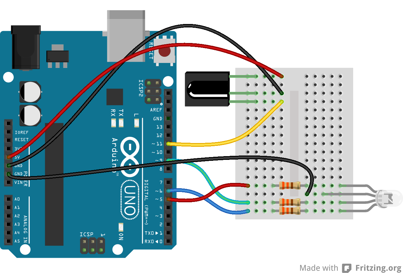
The output of the IR receiver connects to D11, but it could be connected to any digital input pin. If you swap pins, make sure you reflect those changes in code!
We don't have a use for the IR LED yet, so, for now, set that safely aside.
RGB Remote Control
Copy and paste the below code into your Arduino IDE. Then upload it to your Arduino to create your very own, remote controlled, RGB LED.
language:c
/* RGB Remote Control
   by: Jim Lindblom
   SparkFun Electronics
   date: October 1, 2013

   This sketch uses Ken Shirriff's *awesome* IRremote library:
       https://github.com/shirriff/Arduino-IRremote

   RGB Remote Control uses a combination of SparkFun's
   IR Remote (https://www.sparkfun.com/products/11759) and an
   IR receiver diode (https://www.sparkfun.com/products/10266) to
   control an RGB LED.

   The IR Remote's power button turns the LED on or off. The A, B,
   and C buttons select a channel (red, green, or blue). The up
   and down arrows increment or decrement the LED brightness on that channel.
   The left and right arrows turn a channel to min or max, and
   circle set it to the middle.

   Hardware setup:
     * The output of an IR Receiver Diode (38 kHz demodulating
       version) should be connected to the Arduino's pin 11.
       * The IR Receiver diode should also be powered off the
         Arduino's 5V and GND rails.
     * A common cathode RGB LED is connected to Arduino's pins
       5, 9, and 6 (red, green, and blue pins).
 */

#include <IRremote.h> // Include the IRremote library

/* Setup constants for SparkFun's IR Remote: */
#define NUM_BUTTONS 9 // The remote has 9 buttons
/* Define the IR remote button codes. We're only using the
   least signinficant two bytes of these codes. Each one
   should actually have 0x10EF in front of it. Find these codes
   by running the IRrecvDump example sketch included with
   the IRremote library.*/

//------------------------------------------------------------
//Codes for Infrared Remote Control
//COM-11759 https://www.sparkfun.com/products/retired/11759
//Note: Uncomment out this section if you are using this w/ the older remote.

/*
const uint16_t BUTTON_POWER = 0xD827; // i.e. 0x10EFD827
const uint16_t BUTTON_A = 0xF807;
const uint16_t BUTTON_B = 0x7887;
const uint16_t BUTTON_C = 0x58A7;
const uint16_t BUTTON_UP = 0xA05F;
const uint16_t BUTTON_DOWN = 0x00FF;
const uint16_t BUTTON_LEFT = 0x10EF;
const uint16_t BUTTON_RIGHT = 0x807F;
const uint16_t BUTTON_CIRCLE = 0x20DF;
*/
//------------------------------------------------------------
//Codes for Infrared Remote Control
//COM-14865 https://www.sparkfun.com/products/14865
//Note: Comment out this section if you are using this w/ the older remote.

const uint16_t BUTTON_POWER = 0x629D;
const uint16_t BUTTON_A = 0x22DD;
const uint16_t BUTTON_B = 0x02FD;
const uint16_t BUTTON_C = 0xC23D;
const uint16_t BUTTON_UP = 0x9867;
const uint16_t BUTTON_DOWN = 0x38C7;
const uint16_t BUTTON_LEFT = 0x30CF;
const uint16_t BUTTON_RIGHT = 0x7A85;
const uint16_t BUTTON_CIRCLE = 0x18E7;

//------------------------------------------------------------

/* Connect the output of the IR receiver diode to pin 11. */
int RECV_PIN = 11;
/* Initialize the irrecv part of the IRremote  library */
IRrecv irrecv(RECV_PIN);
decode_results results; // This will store our IR received codes
uint16_t lastCode = 0; // This keeps track of the last code RX'd

/* Setup RGB LED pins: */
enum ledOrder // Make an enum to add some clarity in the code
{
  RED,   // 0
  GREEN, // 1
  BLUE   // 2
};
const int rgbPins[3] = {5, 9, 6}; // Red, green, blue pins respectively
byte rgbValues[3] = {55, 23, 200}; // This keeps track of channel brightness
byte activeChannel = RED; // Start with RED as the active channel
boolean ledEnable = 1; // Start with the LED on.

void setup()
{
  Serial.begin(9600); // Use serial to debug.
  irrecv.enableIRIn(); // Start the receiver

  /* Set up the RGB LED pins: */
  for (int i=0; i<3; i++)
  {
    pinMode(rgbPins[i], OUTPUT);
    analogWrite(rgbPins[i], rgbValues[i]);
  }
}

// loop() constantly checks for any received IR codes. At the
// end it updates the RGB LED.
void loop()
{
  if (irrecv.decode(&results))
  {
    /* read the RX'd IR into a 16-bit variable: */
    uint16_t resultCode = (results.value & 0xFFFF);

    /* The remote will continue to spit out 0xFFFFFFFF if a
     button is held down. If we get 0xFFFFFFF, let's just
     assume the previously pressed button is being held down */
    if (resultCode == 0xFFFF)
      resultCode = lastCode;
    else
      lastCode = resultCode;

    // This switch statement checks the received IR code against
    // all of the known codes. Each button press produces a
    // serial output, and has an effect on the LED output.
    switch (resultCode)
    {
      case BUTTON_POWER:
        Serial.println("Power, Turn LED ON/OFF");
        if (ledEnable) ledEnable = 0;
        else ledEnable = 1; // Flip ledEnable
        break;
      case BUTTON_A:
        Serial.println("A, Red");
        activeChannel = RED;
        break;
      case BUTTON_B:
        Serial.println("B, Green");
        activeChannel = GREEN;
        break;
      case BUTTON_C:
        Serial.println("C, Blue");
        activeChannel = BLUE;
        break;
      case BUTTON_UP:
        Serial.println("Up, Increment brightness by 1");
        rgbValues[activeChannel]++; // Increment brightness
        break;
      case BUTTON_DOWN:
        Serial.println("Down, Decrement brightness by 1");
        rgbValues[activeChannel]--; // Decrement brightness
        break;
      case BUTTON_LEFT:
        Serial.println("Left, Min brightness (off)");
        rgbValues[activeChannel] = 0; // Min brightness (off)
        break;
      case BUTTON_RIGHT:
        Serial.println("Right, Max brightness");
        rgbValues[activeChannel] =  255; // Max brightness
        break;
      case BUTTON_CIRCLE:
        Serial.println("Circle, Medium Brightness");
        rgbValues[activeChannel] = 127; // Medium brightness
        break;
      default:
        Serial.print("Unrecognized code received: 0x");
        Serial.println(results.value, HEX);
        break;
    }
    irrecv.resume(); // Receive the next value
  }

  // Every time through the loop, update the RGB LEDs:
  if (ledEnable)
  {
    for (int i=0; i<3; i++)
    {
      analogWrite(rgbPins[i], rgbValues[i]);
    }
  }
  else
  {
    for (int i=0; i<3; i++)
    {
      analogWrite(rgbPins[i], 0);
    }
  }
}
When the code initializes, the RGB LED will be set to a certain brightness. Then we're basically looping and checking to see if the IR receiver diode has received a known code from the IR remote. If so, it'll have some effect on the LED -- turning it on/off, turning up or down red/green/blue, etc. Pressing on the buttons A, B, or C will allow you to adjust the corresponding color. Once a letter is pressed, you can adjust the brightness with the direction pad. Check the comments in the code for help understanding what's going on.
You can also check the output of the serial monitor to make sure the codes are being received. When a known code is received, it'll print out the corresponding button. When an unknown code is received (which shouldn't be often, if ever, if you're only using the SparkFun IR remote), it'll print that code out in hexadecimal.
Play!
That's all there is to it! Try exploring the code and replacing the RGB LED with other devices you can control. How about a servo motor? Or a relay! There are so many possibilities!
Do you have other IR remotes around? Try them out! As you press a button, check the serial monitor (at 9600 bps) to see what code it spits out. Then add a case for those in the switch statement.
Example 3: Transmitting
After you've gotten the remote and receiver working, it's time to add some IR transmission to the setup.
For this example, we'll set up an infrared data relay using both the receiver and an IR LED to transmit data. IR codes received by the Arduino can be sent out the LED by the press of a button.
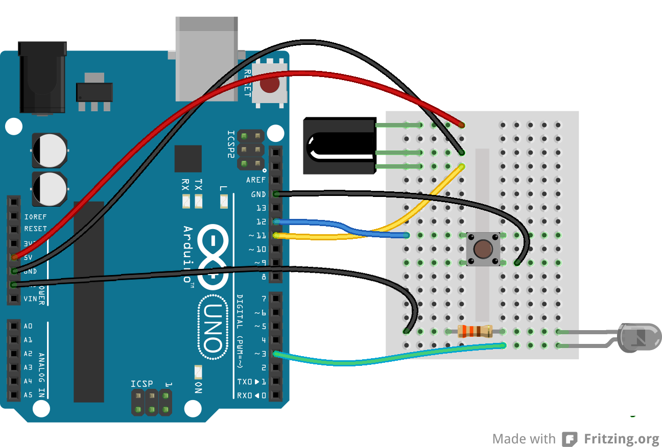
Setting Up the Hardware
On the hardware level, using the IRremote library, there's only one pin we can use to transmit IR data: pin 3. There's not any give here; pin 3's PWM-capabilities make it one of the best choices for transmitting the 38kHz modulated IR data.
We'll also be adding a button to this circuit. If you don't have a button around, you can simply pull pin 12 LOW to emulate a button press. Here's the whole circuit:
Adding Code
Once you've got the hardware all wired up, copy and paste the code below. Then upload it to your Arduino.
language:c
/* IRrecord (Redux)
   by: Jim Lindblom
   SparkFun Electronics
   date: October 1, 2013

   This sketch uses Ken Shirriff's *awesome* IRremote library:
       https://github.com/shirriff/Arduino-IRremote
   It's a slightly modified version of the IRrecord example that
   comes with that library.

   This sketch uses the IR receiver diode to "record" an IR code.
   Then, when triggered via a button on pin 12, it will transmit
   that IR code out of an attached IR LED on pin 3.

   Hardware setup:
     * The output of an IR Receiver Diode (38 kHz demodulating
       version) should be connected to the Arduino's pin 11.
       * The IR Receiver diode should also be powered off the
         Arduino's 5V and GND rails.
     * The anode (+, longer leg) of an IR LED should be connected to pin 3 of
       the Arduino. The cathode (-) should be connected to a 330
       Ohm resistor, which connects to ground.
     * A button should be connected to ground on one end, and pin
       12 of the Arduino on the other.

*/
#include <IRremote.h> // Include the IRremote library

/* Connect the output of the IR receiver diode to pin 11. */
int RECV_PIN = 11;
/* Initialize the irrecv part of the IRremote  library */
IRrecv irrecv(RECV_PIN);
decode_results results; // This will store our IR received codes

IRsend irsend; // Enables IR transmit on pin 3

/* Storage variables for the received IR code: */
unsigned int irLen = 0; // The length of the code
unsigned int irBuffer[RAWBUF]; // Storage for raw (UNKNOWN) codes
int codeType; // The type of code (NEC, SONY, UNKNOWN, etc.)
unsigned int codeValue; // The value of a known code
boolean codeReceived = false; // A boolean to keep track of if a code was received

const int buttonPin = 12; // Button pin. Pulled up. Triggered when connected to ground.

// setup() initializes serial and the Infrared receiver.
void setup()
{
  Serial.begin(9600);
  irrecv.enableIRIn(); // Start the receiver

  pinMode(buttonPin, INPUT_PULLUP);
}

// loop() checks for either a button press or a received IR code.
void loop()
{
  if (irrecv.decode(&results))
  {
    updateIRReceive(); // Sort out the received code
    codeReceived = true; // Enables code transmit on button press
    irrecv.resume(); // re-enable receive
  }

  // If the button is pressed, and we've received a code...
  if ((digitalRead(buttonPin) == LOW) && (codeReceived == true))
  {
    sendCode(); // Sends out our code. (See bottom of sketch).
    irrecv.enableIRIn(); // Re-enable receiver
    // We only want to be able to send the code once. Re-set
    // codeReceived to false:
    codeReceived = false;
  }
}

/* This function reads in the received IR data, and updates the
   following variables:
    * codeType -- How was the IR signal encoded? SONY, NEC,
      UNKNOWN, etc.
    * irLen -- The length (number of marks and ticks) of an IR code.
    * Depending on the codeType, one of these two variables will
      be updated as well:
      * codeValue -- IF the codeType is a known type, this variable
        will contain the received code.
      * irBuffer -- If the codeType is UNKNOWN, this buffer will
        contain the format of the received code.

    This function borrows heavily from the IRrecord example code.
*/
void updateIRReceive()
{
  codeType = results.decode_type;
  irLen = results.rawlen;
  if (codeType == UNKNOWN)
  {
    irLen--;
    // We need to convert from ticks to microseconds
    for (int i = 1; i <= irLen; i++)
    {
      if (i % 2)
      {
        // Mark
        irBuffer[i-1] = results.rawbuf[i]*USECPERTICK - MARK_EXCESS;
        Serial.print(" m");
      }
      else
      {
        // Space
        irBuffer[i-1] = results.rawbuf[i]*USECPERTICK + MARK_EXCESS;
        Serial.print(" s");
      }
      Serial.print(irBuffer[i-1], DEC);
    }
    Serial.println();
  }
  else
  {
    if (codeType == NEC)
    {
      Serial.print("Received NEC: ");
      if (results.value == REPEAT)
      {
        // Don't record a NEC repeat value as that's useless.
        Serial.println("repeat; ignoring.");
        return;
      }
    }
    else if (codeType == SONY)
    {
      Serial.print("Received SONY: ");
    }
    else if (codeType == RC5)
    {
      Serial.print("Received RC5: ");
    }
    else if (codeType == RC6)
    {
      Serial.print("Received RC6: ");
    }
    else
    {
      Serial.print("Unexpected codeType ");
      Serial.print(codeType, DEC);
      Serial.println("");
    }
    Serial.println(results.value, HEX);
    codeValue = results.value;
    irLen = results.bits;
  }
}


void sendCode()
{
  if (codeType == NEC)
  {
    irsend.sendNEC(codeValue, irLen);
    Serial.print("Sent NEC ");
    Serial.println(codeValue, HEX);
  }
  else if (codeType == SONY)
  {
    irsend.sendSony(codeValue, irLen);
    Serial.print("Sent Sony ");
    Serial.println(codeValue, HEX);
  }
  else if (codeType == RC5 || codeType == RC6)
  {
    // Put the toggle bit into the code to send
    codeValue = codeValue & ~(1 << (irLen - 1));
    if (codeType == RC5)
    {
      Serial.print("Sent RC5 ");
      Serial.println(codeValue, HEX);
      irsend.sendRC5(codeValue, irLen);
    }
    else
    {
      irsend.sendRC6(codeValue, irLen);
      Serial.print("Sent RC6 ");
      Serial.println(codeValue, HEX);
    }
  }
  else if (codeType == UNKNOWN /* i.e. raw */)
  {
    // Assume 38 KHz
    irsend.sendRaw(irBuffer, irLen, 38);
    Serial.println("Sent raw");
  }
}
To use the sketch, you'll still need an IR remote. Begin by opening the serial monitor (at 9600 bps). Then press a button on the remote. The serial monitor should notify you that a IR code was received. The Arduino's now all loaded up, ready to spit out its own IR code.
To send out the IR code, press the button connected to pin 12 (or just short a jumper wire from 12 to GND). The way the example code is written, the IR LED will send the IR code once until the Arduino receives another IR code to record. Unless you have a device that is looking for specific IR codes, you may not see anything happen. Try the sketch out with some IR remotes and appliances around your house. Can your Arduino trigger your TV to mute?
Delving Into IR Sends
If you're using the IRremote library to transmit data, there are just a few lines of code you'll need to add. First, you'll need to declare an instance of IRsend at the top of your code:
language:c
IRsend irsend;
There are a variety of transmitting options made available by the library. They vary by encoding scheme, which usually depends on the manufacturer. You can use any of these functions to send out IR data:
language:c
void sendNEC(unsigned long data, int nbits);
void sendSony(unsigned long data, int nbits);
void sendRC5(unsigned long data, int nbits);
void sendRC6(unsigned long data, int nbits);
void sendDISH(unsigned long data, int nbits);
void sendSharp(unsigned long data, int nbits);
void sendPanasonic(unsigned int address, unsigned long data);
void sendJVC(unsigned long data, int nbits, int repeat);

void sendRaw(unsigned int buf[], int len, int hz);
If you don't have an appliance matching any of those manufacturers (NEC, Sony, DISH, Sharp, Panasonic, JVC, etc.), you'll have to use the sendRaw function to transmit your IR code.
If you want to drive an IR LED properly, consider using the IR LED with a transistor and resistor that was used in the design of the old SparkFun Max Power IR LED kit. To control, simply provide it with voltage (5V), ground, and connect the CTL pin to a digital pin on your Arduino, and you can drive this kit just like a normal LED. However, a 330Ω attached to your IR LED should give about 10 feet of range.
Resources and Going Further
Thanks for checking out our IR Control Kit hookup guide! If you're looking for more documents and resources related to the kit, check out some of these links:
- Datasheet
- IRremote Library
- GitHub Repo: SparkFun IR Control Kit
- SFE Product Showcase
If you're looking for general information on infrared communication check out our IR Communication tutorial, as well as SparkFun Engineer Chris Taylor's IR Project video:
ReplaceMeOpen
ReplaceMeClose
And there's also Jeff Branson, starring in an IR Communication video tutorial using our IR Emitter/Detector Pair:
Now that you've discovered how easy it is to add infrared output or input to your project, what are you going to control with this extravisible, modulated light source? Need some inspiration? Check out some of these tutorials:
- LED Light Bar Hookup -- If you need some visible light in your life, these LED light bars are an especially bright way to get it
- Using the OpenSegment -- Along the lines of visible displays, the OpenSegment 4-digit 7-segment displays are an easy tool to add data displays to your project.
- Rebuilding the Illumitune -- Learn how we integrated IR into the Illumitune project we helped rebuild.
- Laser Limbo -- Build a "Laser" limbo using IR LEDs and IR Receivers!