IR Control Kit Hookup Guide
 jimblom,
  bboyho
 Hardware Overview
Before we dig into wiring stuff up and uploading sketches, let's quickly overview each of the components in the IR Control Kit.
IR LED
Let's start with simplest of the components first -- the infrared LED. Anyone who's ever worked with electronics has blinked an LED, but those blinking LEDs are usually in our visual spectrum. These IR LEDs are just like any LED you've blinked before, but they emit light at a wavelength of about 950nm -- radiation well outside of our visual range (about 390 to 700nm).
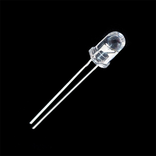
You can't see these LEDs light up, but you can still use them just like any LED. They still have two polarized legs: an anode (positive, the long leg) and a cathode. They have a typical forward voltage of about 1.5V, and a maximum forward current of 50mA. For more specs, you can check out the LED's datasheet.
330Ω Current Limiting Resistor
Just as with any LED, the IR LED needs a series resistor to limit current. That's what the included 330Ω resistors are for.
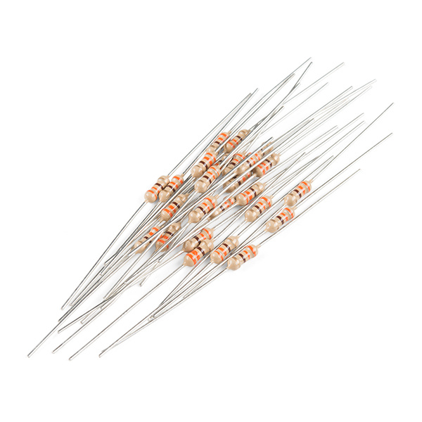
With a 5V supply connected to the resistor/LED series combo, current through the LED should be limited to about 10mA, which is well inside its safe operating range.
TSOP38238 IR Receiver Module
While it may look like a simple transistor, the TSOP38238 IR receiver module is actually a unique, light-demodulating integrated circuit.
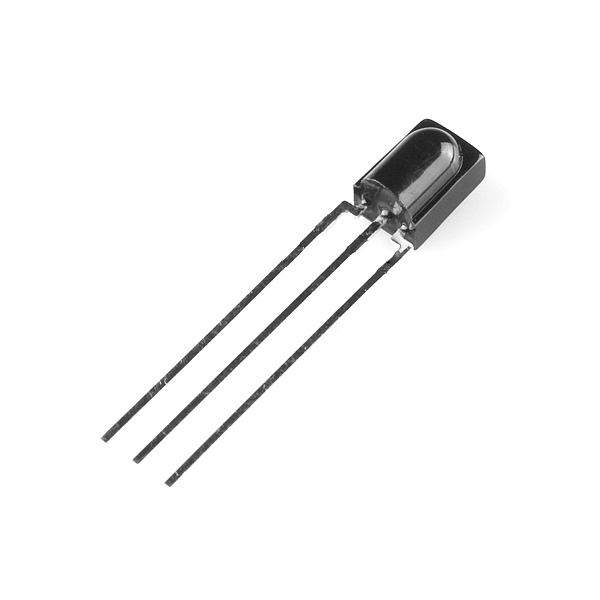
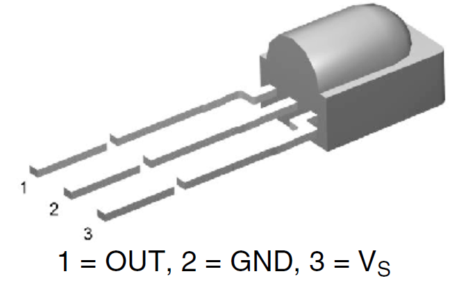
With three pins, it's about as simple as an IC can get. There are two pins for power -- ground in the middle, and VS to a side -- and one, single data output pin.
The IR receiver can be powered at anywhere from 2.5V to 5.5V, so it plays very nicely with a variety of development boards.
This module is tuned to demodulate 38kHz signals, which are a very common in the IR signal world. It turns a spiky, modulated signal (as shown on the image on the left) into this cleaner much easier to read signal (as shown in the image on the right):
 |
 |
So all we have to do to read the output of this device is count high and low pulses, and measure their durations. For more information on the TSOP38238, check out its datasheet.
IR Remote
Finally, we come to the flashy part of the kit: SparkFun's custom-made Infrared Remote Control.
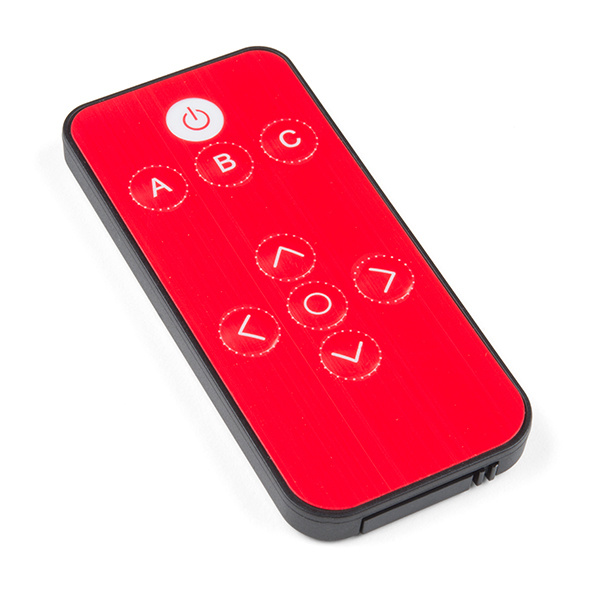
Infrared Remote Control
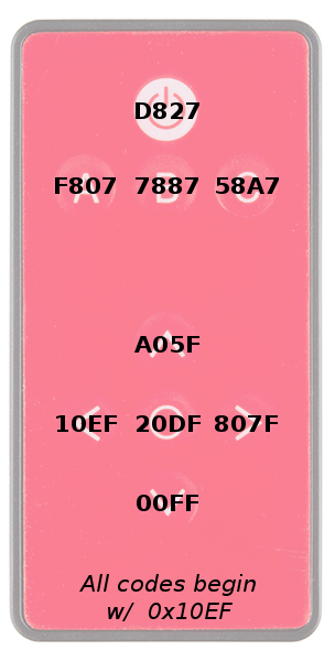
COM-14865The nine button remote emits unique 32-bit codes for each button press. The codes are mapped as shown in the images below (this will come in handy in our first example). Depending on the IR remote that you are using, the values may be different.
 |
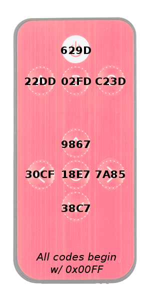 |
| Hex Codes for COM-11759 | Hex Codes for COM-14865 |
The remote's infrared output signal is modulated at 38kHz, so it works perfectly with the IR receiver module.
How to Battery?
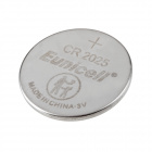
The IR remote doesn't come with a battery installed but the IR Control Kit includes one for it. The battery compartment can be found on the bottom edge of the remote. To open the battery compartment, pinch the latch with your thumbnail while pushing the drawer out with another fingernail.
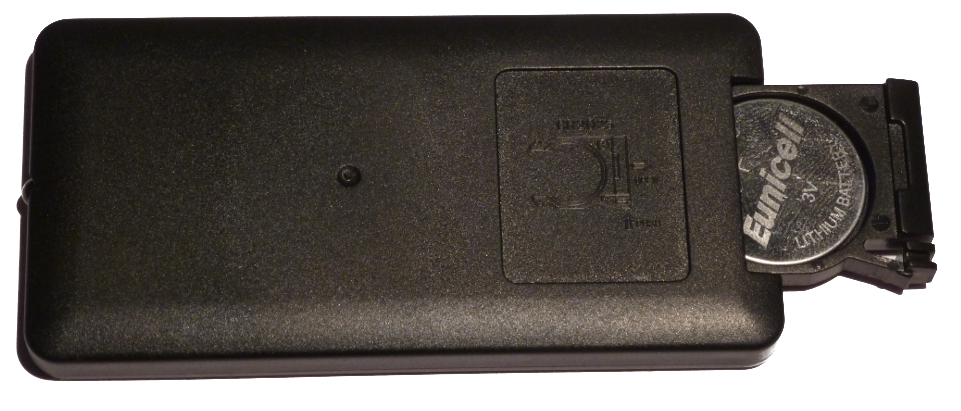
Insert the battery so that the positive (+) side is facing the bottom of the remote. Then slide the battery drawer back in.