IR Control Kit Hookup Guide
 jimblom,
  bboyho
Example 2: Using the Remote
In the first example, we'll show how you can connect the IR receiver to an Arduino, and control it with the IR remote.
Circuit Diagram
In this first example, we'll use the IR receiving capabilities of the IRremote library to use the SparkFun IR remote to control a common cathode RGB LED. An RGB LED isn't included with the IR Control Kit, but it might be something you've already got in your parts box. If not, any set of three will do. Or you can even just use the serial monitor as your output monitor.
This is how we'll connect the IR receiver and RGB LED to our Arduino:
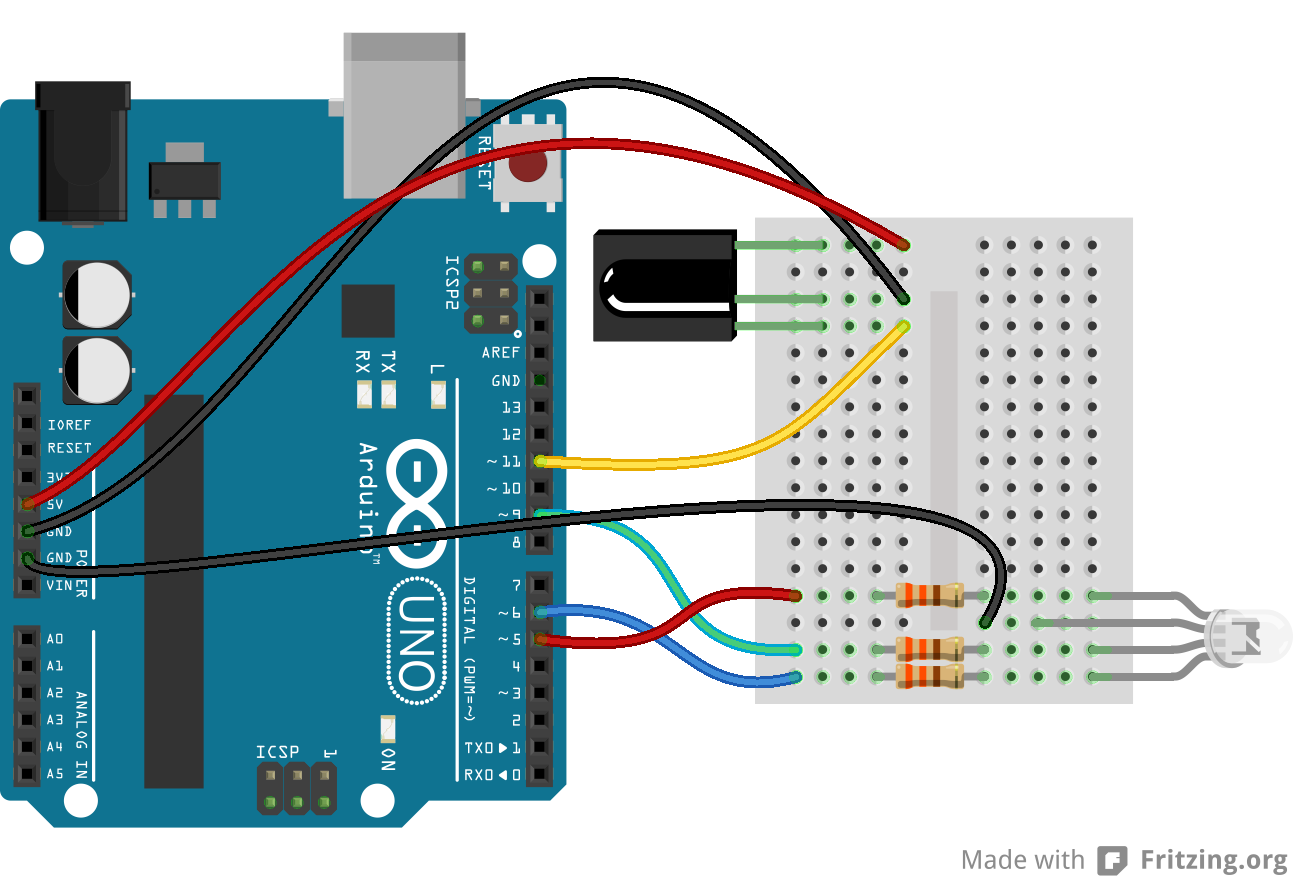
The output of the IR receiver connects to D11, but it could be connected to any digital input pin. If you swap pins, make sure you reflect those changes in code!
We don't have a use for the IR LED yet, so, for now, set that safely aside.
RGB Remote Control
Copy and paste the below code into your Arduino IDE. Then upload it to your Arduino to create your very own, remote controlled, RGB LED.
language:c
/* RGB Remote Control
   by: Jim Lindblom
   SparkFun Electronics
   date: October 1, 2013

   This sketch uses Ken Shirriff's *awesome* IRremote library:
       https://github.com/shirriff/Arduino-IRremote

   RGB Remote Control uses a combination of SparkFun's
   IR Remote (https://www.sparkfun.com/products/11759) and an
   IR receiver diode (https://www.sparkfun.com/products/10266) to
   control an RGB LED.

   The IR Remote's power button turns the LED on or off. The A, B,
   and C buttons select a channel (red, green, or blue). The up
   and down arrows increment or decrement the LED brightness on that channel.
   The left and right arrows turn a channel to min or max, and
   circle set it to the middle.

   Hardware setup:
     * The output of an IR Receiver Diode (38 kHz demodulating
       version) should be connected to the Arduino's pin 11.
       * The IR Receiver diode should also be powered off the
         Arduino's 5V and GND rails.
     * A common cathode RGB LED is connected to Arduino's pins
       5, 9, and 6 (red, green, and blue pins).
 */

#include <IRremote.h> // Include the IRremote library

/* Setup constants for SparkFun's IR Remote: */
#define NUM_BUTTONS 9 // The remote has 9 buttons
/* Define the IR remote button codes. We're only using the
   least signinficant two bytes of these codes. Each one
   should actually have 0x10EF in front of it. Find these codes
   by running the IRrecvDump example sketch included with
   the IRremote library.*/

//------------------------------------------------------------
//Codes for Infrared Remote Control
//COM-11759 https://www.sparkfun.com/products/retired/11759
//Note: Uncomment out this section if you are using this w/ the older remote.

/*
const uint16_t BUTTON_POWER = 0xD827; // i.e. 0x10EFD827
const uint16_t BUTTON_A = 0xF807;
const uint16_t BUTTON_B = 0x7887;
const uint16_t BUTTON_C = 0x58A7;
const uint16_t BUTTON_UP = 0xA05F;
const uint16_t BUTTON_DOWN = 0x00FF;
const uint16_t BUTTON_LEFT = 0x10EF;
const uint16_t BUTTON_RIGHT = 0x807F;
const uint16_t BUTTON_CIRCLE = 0x20DF;
*/
//------------------------------------------------------------
//Codes for Infrared Remote Control
//COM-14865 https://www.sparkfun.com/products/14865
//Note: Comment out this section if you are using this w/ the older remote.

const uint16_t BUTTON_POWER = 0x629D;
const uint16_t BUTTON_A = 0x22DD;
const uint16_t BUTTON_B = 0x02FD;
const uint16_t BUTTON_C = 0xC23D;
const uint16_t BUTTON_UP = 0x9867;
const uint16_t BUTTON_DOWN = 0x38C7;
const uint16_t BUTTON_LEFT = 0x30CF;
const uint16_t BUTTON_RIGHT = 0x7A85;
const uint16_t BUTTON_CIRCLE = 0x18E7;

//------------------------------------------------------------

/* Connect the output of the IR receiver diode to pin 11. */
int RECV_PIN = 11;
/* Initialize the irrecv part of the IRremote  library */
IRrecv irrecv(RECV_PIN);
decode_results results; // This will store our IR received codes
uint16_t lastCode = 0; // This keeps track of the last code RX'd

/* Setup RGB LED pins: */
enum ledOrder // Make an enum to add some clarity in the code
{
  RED,   // 0
  GREEN, // 1
  BLUE   // 2
};
const int rgbPins[3] = {5, 9, 6}; // Red, green, blue pins respectively
byte rgbValues[3] = {55, 23, 200}; // This keeps track of channel brightness
byte activeChannel = RED; // Start with RED as the active channel
boolean ledEnable = 1; // Start with the LED on.

void setup()
{
  Serial.begin(9600); // Use serial to debug.
  irrecv.enableIRIn(); // Start the receiver

  /* Set up the RGB LED pins: */
  for (int i=0; i<3; i++)
  {
    pinMode(rgbPins[i], OUTPUT);
    analogWrite(rgbPins[i], rgbValues[i]);
  }
}

// loop() constantly checks for any received IR codes. At the
// end it updates the RGB LED.
void loop()
{
  if (irrecv.decode(&results))
  {
    /* read the RX'd IR into a 16-bit variable: */
    uint16_t resultCode = (results.value & 0xFFFF);

    /* The remote will continue to spit out 0xFFFFFFFF if a
     button is held down. If we get 0xFFFFFFF, let's just
     assume the previously pressed button is being held down */
    if (resultCode == 0xFFFF)
      resultCode = lastCode;
    else
      lastCode = resultCode;

    // This switch statement checks the received IR code against
    // all of the known codes. Each button press produces a
    // serial output, and has an effect on the LED output.
    switch (resultCode)
    {
      case BUTTON_POWER:
        Serial.println("Power, Turn LED ON/OFF");
        if (ledEnable) ledEnable = 0;
        else ledEnable = 1; // Flip ledEnable
        break;
      case BUTTON_A:
        Serial.println("A, Red");
        activeChannel = RED;
        break;
      case BUTTON_B:
        Serial.println("B, Green");
        activeChannel = GREEN;
        break;
      case BUTTON_C:
        Serial.println("C, Blue");
        activeChannel = BLUE;
        break;
      case BUTTON_UP:
        Serial.println("Up, Increment brightness by 1");
        rgbValues[activeChannel]++; // Increment brightness
        break;
      case BUTTON_DOWN:
        Serial.println("Down, Decrement brightness by 1");
        rgbValues[activeChannel]--; // Decrement brightness
        break;
      case BUTTON_LEFT:
        Serial.println("Left, Min brightness (off)");
        rgbValues[activeChannel] = 0; // Min brightness (off)
        break;
      case BUTTON_RIGHT:
        Serial.println("Right, Max brightness");
        rgbValues[activeChannel] =  255; // Max brightness
        break;
      case BUTTON_CIRCLE:
        Serial.println("Circle, Medium Brightness");
        rgbValues[activeChannel] = 127; // Medium brightness
        break;
      default:
        Serial.print("Unrecognized code received: 0x");
        Serial.println(results.value, HEX);
        break;
    }
    irrecv.resume(); // Receive the next value
  }

  // Every time through the loop, update the RGB LEDs:
  if (ledEnable)
  {
    for (int i=0; i<3; i++)
    {
      analogWrite(rgbPins[i], rgbValues[i]);
    }
  }
  else
  {
    for (int i=0; i<3; i++)
    {
      analogWrite(rgbPins[i], 0);
    }
  }
}
When the code initializes, the RGB LED will be set to a certain brightness. Then we're basically looping and checking to see if the IR receiver diode has received a known code from the IR remote. If so, it'll have some effect on the LED -- turning it on/off, turning up or down red/green/blue, etc. Pressing on the buttons A, B, or C will allow you to adjust the corresponding color. Once a letter is pressed, you can adjust the brightness with the direction pad. Check the comments in the code for help understanding what's going on.
You can also check the output of the serial monitor to make sure the codes are being received. When a known code is received, it'll print out the corresponding button. When an unknown code is received (which shouldn't be often, if ever, if you're only using the SparkFun IR remote), it'll print that code out in hexadecimal.
Play!
That's all there is to it! Try exploring the code and replacing the RGB LED with other devices you can control. How about a servo motor? Or a relay! There are so many possibilities!
Do you have other IR remotes around? Try them out! As you press a button, check the serial monitor (at 9600 bps) to see what code it spits out. Then add a case for those in the switch statement.