IoT Power Relay
 SFUptownMaker
Hardware Hookup
Base Plate
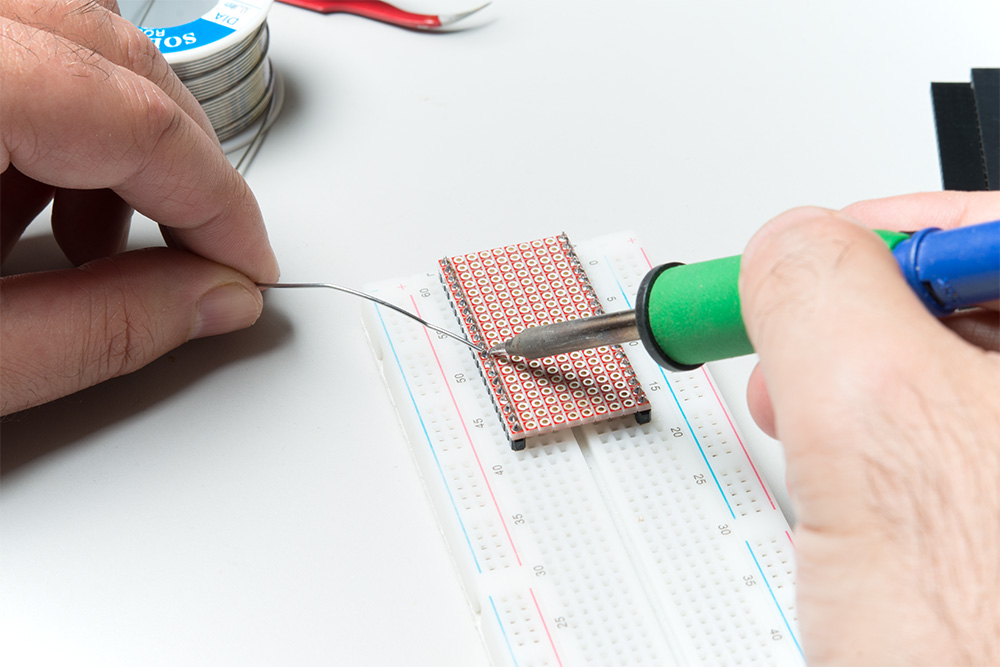
You'll need to use a snappable protoboard to create a base plate to work from. Snap it to a size that will cover the ESP32 without obscuring the antenna--20 holes by 10 holes. We want to solder down male pins to the underside of the base plate, as shown below. Note the use of a breadboard as a fixture to hold the pins perpendicular to the plate.
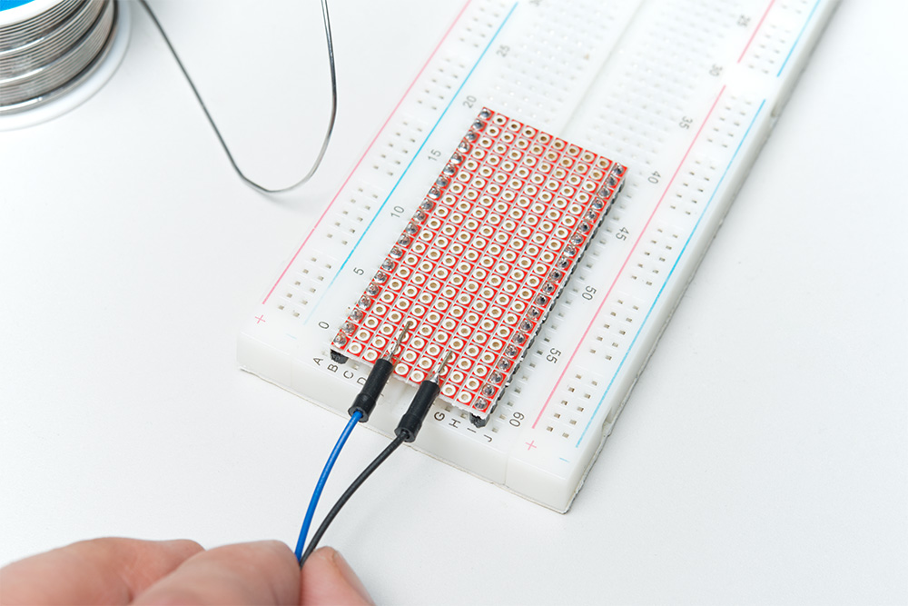
You'll also need to solder down the wires used to connect to the IoT Relay box. I like to use the cheap jumper wires we sell for this purpose, as the plastic ferrule on the ends provides strain relief.
Qwiic Connector
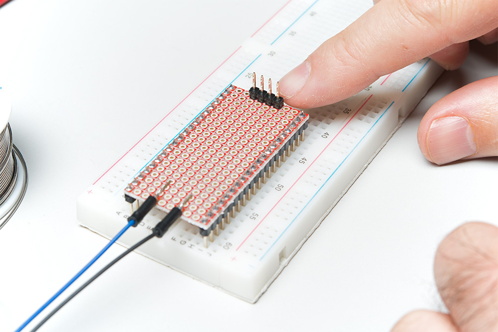
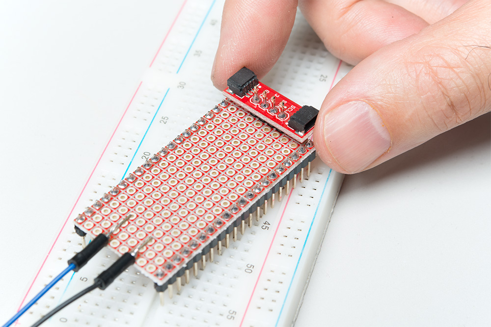
Since we don't have a Qwiic connector handy, we'll use our Qwiic adapter board to provide a Qwiic-compatible connector. Solder the header down as shown below. It should be directly centered on the base plate.
Once you've soldered down the header (you'll need to remove the base plate from the breadboard to access the underside of it), you can solder the adapter to the header on the top side of the board.
Route the Signals
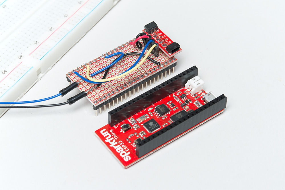
Route the two wires you soldered on earlier to GND and pin 5 (9th pin down on the right hand side, if the edge that will be closest the antenna is on top).
We'll also need to route the signals to the Qwiic adapter -- 3.3V, GND, SDA and SCL. SDA and SCL are broken out to pins 21 and 22, respectively, on the ESP32 Thing. When you're done, you should have something that looks like this:

ESP32 Thing
We want female headers on our Thing board to mate with the male headers on the base plate. You'll need to cut to length the female headers from the wishlist. Remember that you'll lose one pin to the cutting, so you need two pieces of the full size header. In the picture below, note how I'm using the base plate to hold the headers perpendicular to the ESP32 board for soldering.
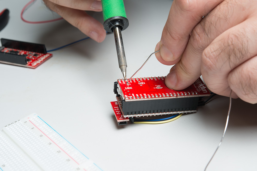
You should now have something that looks a lot like this picture:
Fitting It All Together
It might help to mount the IoT Relay and ESP32 Thing to some kind of base, such as a piece of plywood or even corrugated cardboard, before finishing the assembly. I didn't do that, so I could continue to manipulate the hardware for pictures.
Pull the screw terminal out of the side of the IoT Relay. You won't be able to screw down the wires without doing this.
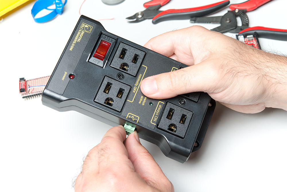
It takes a significant amount of force to pull the screw terminal free of the box, and you may find that you need a pair of pliers or something similar to get it free
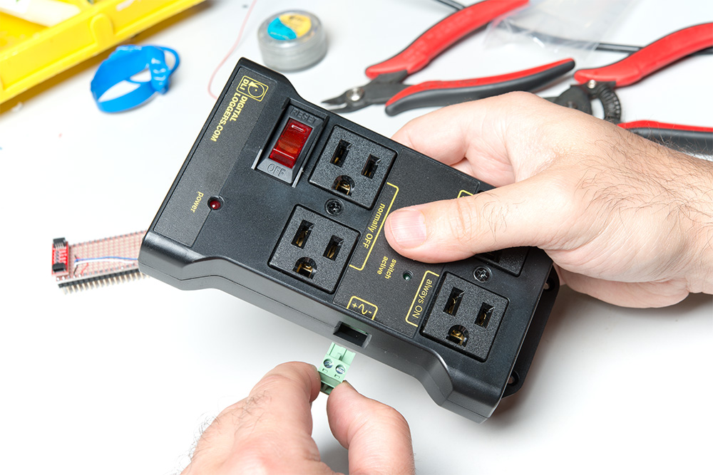
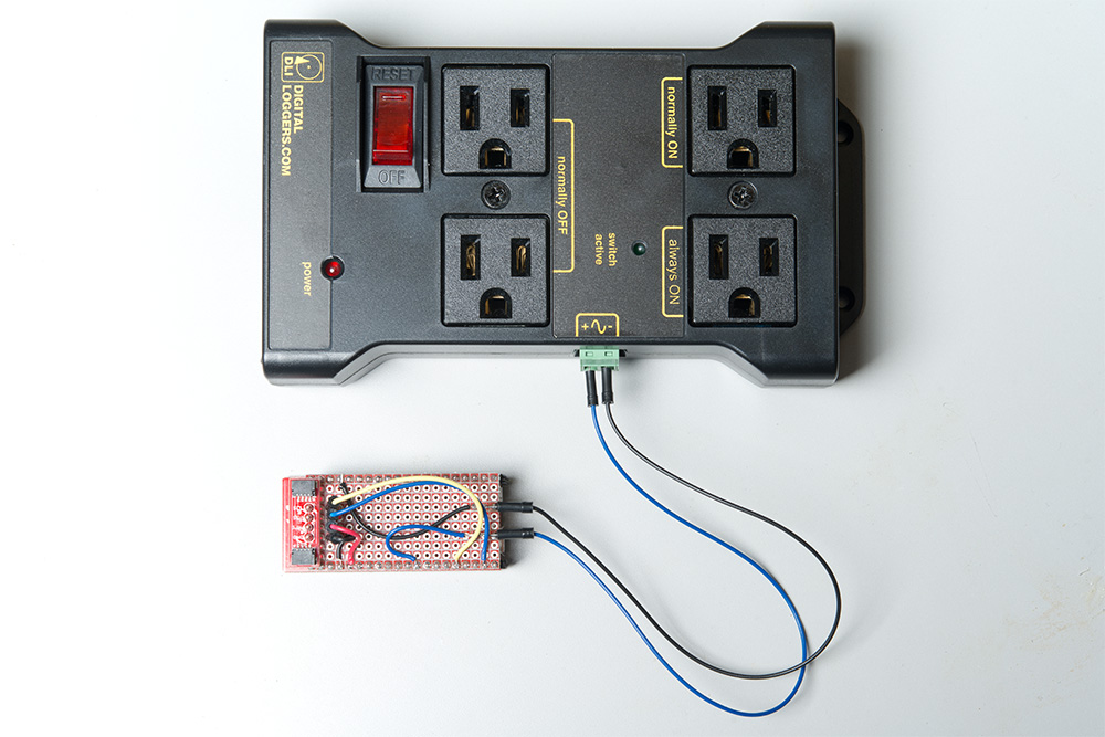
You may now screw the wires you attached to the base plate into the screw terminal block. Note the polarity markings on the IoT Relay box. Make sure you connect the '-' terminal to GND and the '+' terminal to the wire routed to pin 5 on the ESP32 Thing.
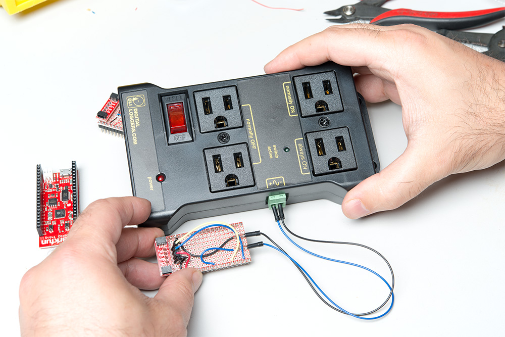
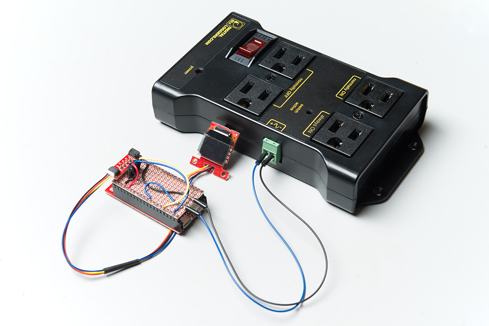
Now, place the base plate onto the ESP32 Thing. Be careful of the orientation, making sure that the Qwiic connector is on the end farthest from the antenna.
Finally, connect the Micro OLED to the Qwiic connector. You'll probably want to affix that to the base along with the ESP32 Thing and the IoT Relay box. I suggest hot glue.