GNSS Correction Data Receiver (NEO-D9S) Hookup Guide
 bboyho,
  PaulZC
Hardware Hookup
To add GNSS correction data to your high precision GNSS receiver like the ZED-F9P, you can connect any of the serial ports between the two boards. If you are using SPI to connect, just make sure to enable the SPI port by adding a solder jumper to the SPI jumper pads. For an embedded application, we recommend adding an ESP32 to the setup. In addition to the Thingstream PointPerfect over L-band satellite, the ESP32 will also allow you to use the Thingstream PointPerfect service over Internet Protocol (IP) using MQTT.
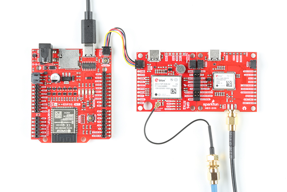
I2C via Qwiic
Below is one example to connect using the I2C port and Qwiic. Simply insert a Qwiic cable between the ZED-F9P, NEO-D9S, and Arduino microcontroller's Qwiic connectors. Plug in a compatible antenna with SMA connector to the ZED-F9P and NEO-D9S board. For the ZED-F9P, you will need the multiband antenna that is capable of receiving L1/L2 bands. For boards that have a u.FL connector, make sure use a u.FL to SMA adapter cable. For the NEO-D9S, you will need to attach an L-Band antenna. Secure the connection on both antennas using the hex nut until it is finger-tight. For power, we will use a USB-C cable to power the ESP32 development board. You can also use this cable to connect each breakout to your computer when using the u-blox u-center software.
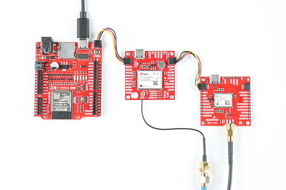
I2C and UART2 Ports via PTH
For those that prefer a PTH connection, you could connect using male header pins, 2-pin jumpers, F/F jumper wires, and M/F jumper wires. In this case, the ZED-F9P and NEO-D9S breakout boards were connected using the male header pins and 2-pin jumpers. The Arduino microcontroller was connected using a Qwiic cable. Of course, you will still need to plug in a compatible antenna with SMA connector to the ZED-F9P and NEO-D9S board. For the ZED-F9P, you will need the multiband antenna that is capable of receiving L1/L2 bands. For boards that have a u.FL connector, make sure use a u.FL to SMA adapter cable. For the NEO-D9S, you will need to attach an L-Band antenna. Secure the connection using the hex nut until it is finger-tight. For power, we will use a USB-C cable to power the ESP32 development board. You can also use this cable to connect each breakout to your computer when using the u-blox u-center software.