Getting Started with the DA16200 FreeRTOS SDK
Serial Debug Interface
Note: This tutorial assumes that users are already familiar with serial terminals and their use. However, for those of who have never heard of them before, feel free to check our tutorials below:
- Depending on the board and/or adapter being utilized, users may need to install the appropriate driver for their computer to recognize the serial-to-UART chip on their board/adapter.
How to Install CH340 Drivers
How to install CH340 drivers (if you need them) on Windows, Mac OS X, and Linux. - Users will also need a serial terminal installed on their computer to access the serial debug interface.
The serial terminal should be configured with the following settings:
- Baud Rate: 230400 bps
- Data Bits: 8 (8-N-1)
- Parity: None
- Stop Bits: 1
- Flow Control (HW/SW): None
Serial Terminal Basics
This tutorial will show you how to communicate with your serial devices using a variety of terminal emulator applications.
The DA16200MOD can be controlled through the serial debug interface with the available console commands. The console is accessed by connecting the UART0 interface of the DA16200MOD module to a serial terminal on a computer.
- To operate various functions of the DA16200MOD module, please refer to Appendix B of the DA16200 FreeRTOS Getting Started Guide for a full list of the available debug interface commands.
- For examples of how to utilize the serial debug interface, please refer to sections 4.4 - 4.6 and section 6 of the DA16200 FreeRTOS Getting Started Guide.
- Section 4.6 - WiFi Provisioning
- Section 6.3 - Throughput Test
- Section 6.4 - Dynamic Power Management (DPM) Setup
Update SDK Firmware
Before proceeding further, users will need to update the firmware for the DA16200MOD.
- There are two firmware images for the DA16200:
- FBOOT is the bootloader image which is used to initialize the DA16200 and launch the main firmware.
- File Name:
DA16200_FBOOT-GEN01-01-XXXXXXXXX_W25Q32JW.img - The bootloader image must be the first thing loaded into flash for a new device.
- Since the bootloader image contains SFDP (flash specific) information, the bootloader must be loaded into flash before other images are loaded.
- When the SDK is updated, always load the bootloader image first.
- File Name:
- FRTOS is the main firmware image which includes the RTOS and user applications.
- File Name:
DA16200_FRTOS-GEN01-01-XXXXXXXXX-XXXXXX.img - There are two slots in the SFlash memory to upload the main firmware image:
RTOS #0begins at0x023000RTOS #1begins at0x1e2000
- File Name:
- FBOOT is the bootloader image which is used to initialize the DA16200 and launch the main firmware.
- The DA16200 SDK can be used to build the firmware images for a specific example project from the DA16200 FreeRTOS SDK.
- Prebuilt versions of the latest firmware for DA16200 can be downloaded from the Renesas product page.
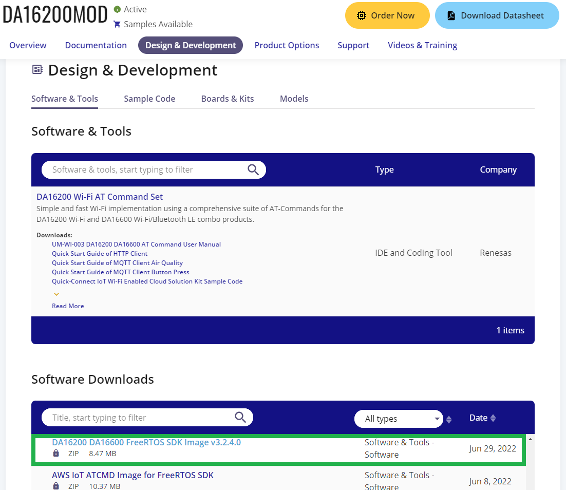
- Users can download the latest images from the Software Downloads section of the Design & Development tab. The firmware images should be named:
DA16200 DA16600 FreeRTOS SDK Image <version>. (Users will need an account to download these files.) Download the latest DA16200 FreeRTOS SDK firmware from the DA16200MOD product page. (Click to enlarge)
- Users can download the latest images from the Software Downloads section of the Design & Development tab. The firmware images should be named:
To update the firmware on the DA16200MOD, users will need to connect to the module to a computer through the serial debug interface. From a serial terminal, users will use Y-Modem to upload the updated SDK bootloader and firmware images to the DA16200MOD.
To update the firmware images on the DA16200:
- In the serial terminal, at the
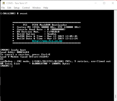
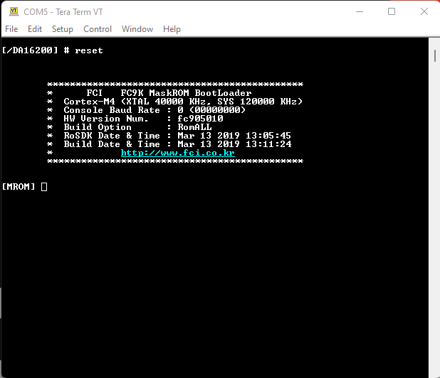
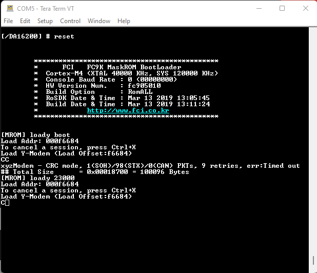
[/DA16xxx]prompt, enterresetto access to the MaskROM mode.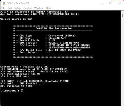 Splash screen and intial prompt for the serial debug interface. (Click to enlarge)
 - At the
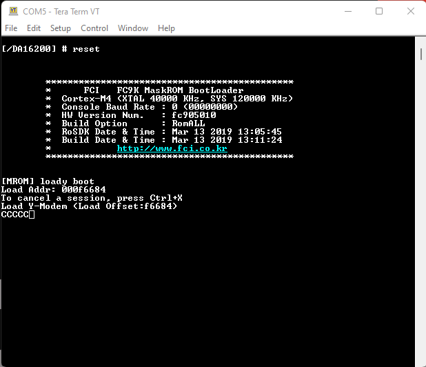
[MROM]prompt, use theloadycommand to upload one of the firmware images. MROM command mode. (Click to enlarge)
- For the second bootloader firmware image (
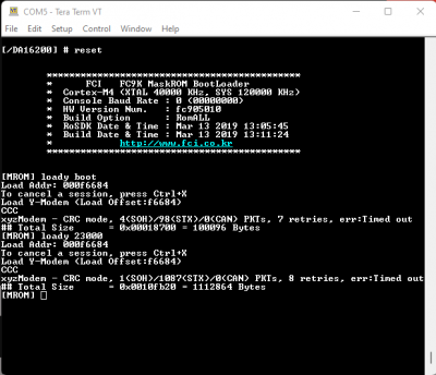
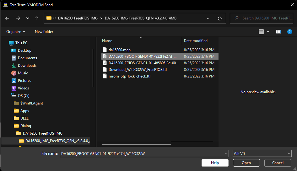
FBOOT), use theloady bootorloady 0command. Command to upload the
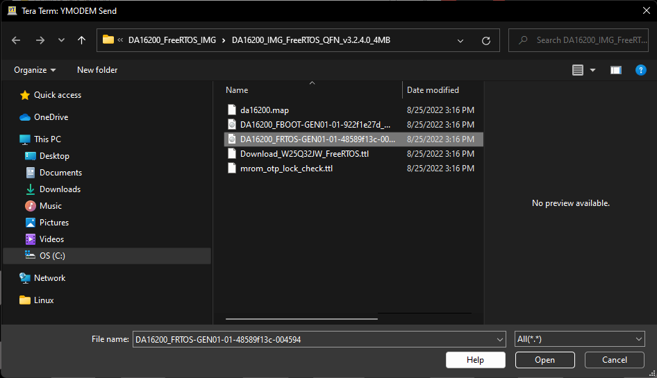
FBOOTimage. (Click to enlarge) - For the main firmware image (
FRTOS), use theloady 23000command (forRTOS #0). Command mode to upload the
FRTOSimage. (Click to enlarge)
- For the second bootloader firmware image (
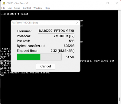
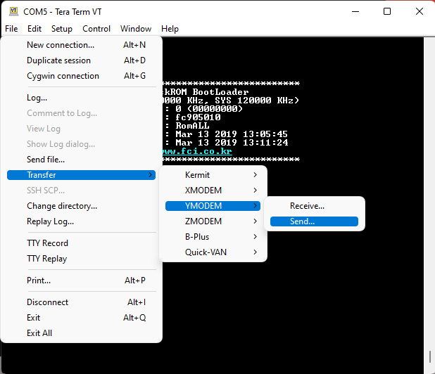
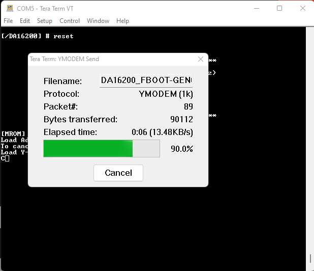
- In the terminal emulation program, start the Y-Modem file transfer:
- For Windows Tera Term:
- From the File menu, select Transfer > YMODEM > Send.
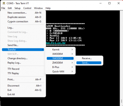 Y-Modem file transfer. (Click to enlarge)
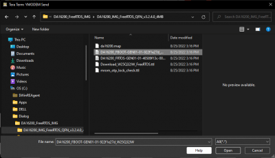
 - Navigate to where the firmware image is stored, choose the required firmware image and start the download.
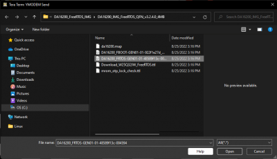 Select firmware image. (Click to enlarge)
- From the File menu, select Transfer > YMODEM > Send.
- For Linux
minicom:- Press Ctrl+A+S and select
ymodemfrom the menu. - Navigate to where the firmware image is stored, choose the required firmware image and start the download.
 Select firmware image. (Click to enlarge)
- Press Ctrl+A+S and select
- For Windows Tera Term:
After the transfer completes, the total size is displayed.

Y-Modem file transfer completed. (Click to enlarge) - When updating the firmware images for a new version of the SDK, both the second bootloader firmware image (
FBOOT) and the main firmware image (FRTOS) must be uploaded.- When uploading a main firmware image (
FRTOS) for a project built with the SDK (no version update), it isn't necessary to upload the second bootloader firmware image (FBOOT).
- When uploading a main firmware image (
- After all firmware images have been uploaded to the DA16200MOD, use the
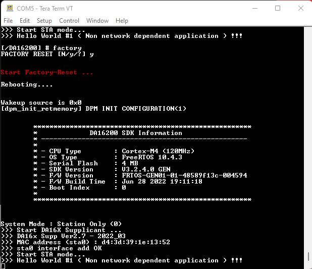
bootcommand at the[MROM]prompt to restart the firmware. - After the firmware reboots, at the
[/DA16200]prompt, users can return the DA16200MOD to a factory configuration state with thefactorycommand.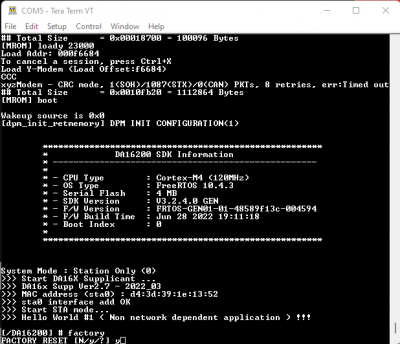 Factory reset command. (Click to enlarge)
- When prompted, enter
yto confirm. Reboot after a factory reset. (Click to enlarge)
- When prompted, enter
- In the serial terminal, at the
- With TeraTerm (Windows only), users can also upload the SDK bootloader and firmware using the TeraTerm script.
- Tera Term script is only available with the prebuilt versions of firmware downloaded from the Renesas product page. (The script is not generated with the images from the DA16200 FreeRTOS SDK project builds.)
- Once terra term is running and connected to the DA16200MOD, open the Control menu and select Macro. When the Macro file selection window opens, navigate to the directory where the firmware images are stored and select the
*.ttlfile. Uploading the SDK bootloader and firmware using the TeraTerm script. (Click to enlarge)


Upload New Project Firmware
The process for uploading new firmware for an SDK project build is a similar method to updating the SDK firmware. Users will need to connect to the module to a computer through the serial debug interface. From a serial terminal, users will use Y-Modem to upload the new firmware image to the DA16200MOD.
- To update the firmware images on the DA16200:
- In the serial terminal, at the
[/DA16xxx]prompt, enterresetto access to the MaskROM mode. Splash screen and intial prompt for the serial debug interface. (Click to enlarge) - At the
[MROM]prompt, use theloadycommand to upload one of the firmware images.- For the main firmware image (
FRTOS), use theloady 23000command forRTOS #0. - When uploading a main firmware image (
FRTOS) for a project built with the SDK (no version update), it isn't necessary to upload the second bootloader firmware image (FBOOT). Command mode to upload theFRTOSimage. (Click to enlarge)
- For the main firmware image (
- In the terminal emulation program, start the Y-Modem file transfer:
- For Windows Tera Term:
- From the File menu, select Transfer > YMODEM > Send.
Y-Modem file transfer. (Click to enlarge)
- Navigate to where the firmware image is stored, choose the required firmware image and start the download.
- From the File menu, select Transfer > YMODEM > Send.
- For Linux
minicom:- Press Ctrl+A+S and select
ymodemfrom the menu. - Navigate to where the firmware image is stored, choose the required firmware image and start the download.
- Press Ctrl+A+S and select
- For Windows Tera Term:
- After the transfer completes, the total size is displayed. Use the
bootcommand at the[MROM]prompt to restart the firmware.
- In the serial terminal, at the
Select the Boot Index
There are two slots, in which the main firmware image FRTOS can be stored in the SFLASH memory. These locations are at RTOS #0 (0x23000) and RTOS #1 (0x1e2000). Through the serial debug interface, users can specify which firmware image that the board boots up with.
- From the command console, the boot index can be changed using the
boot_idxcommandboot_idx 0- setsRTOS #0as the firmware to bootboot_idx 1- setsRTOS #1as the firmware to boot
- After running the
boot_idxcommand, run therebootcommand to boot the firmware that was selected.
Erase Firmware
Users can erase the firmware from the SFLASH memory. This can be performed through the Net command mode.
- From the
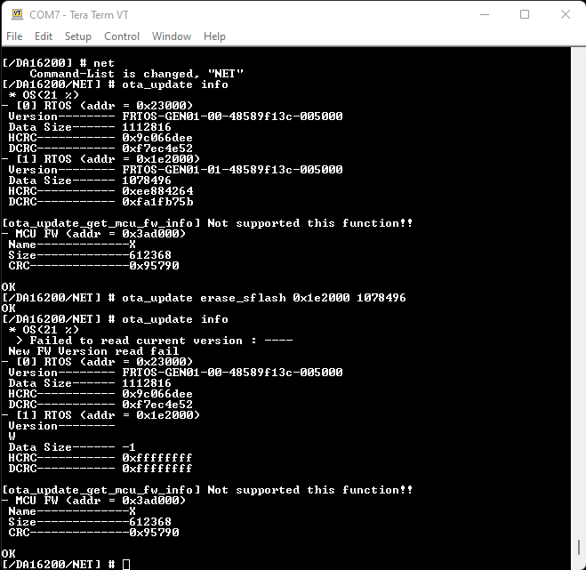
[/DA16200] #prompt, enternetto enter the NET command mode. - From the
[/DA16200/NET] #prompt, enter theota_update infocommand to display the firmware information from the SFLASH memory - Users can then use the
ota_update erase_sflash <start> <size>command to erase a section of the 4MB SFLASH memory.- Example: To remove the firmware operating in the
RTOS #1section (0x1e2000) with 1078496 bytes of memory, users will use the commandota_update erase_sflash 0x1e2000 1078496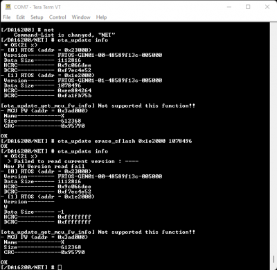 Erasing the firmware from the SFLASH memory for
RTOS #1. (Click to enlarge)
- Example: To remove the firmware operating in the
WiFi Provisioning
To configure the WiFi connection of the DA16200 Thing Plus, follow the instructions below:
- From the
[/DA16200] #prompt, entersetup. - Users will then be prompted
Stop all services for the setting. Are you sure ? [Yes/No] :.- Select yes, by returning
y.
- Select yes, by returning
- After, country code list will be displayed and users will be prompted for their country code.
- Users that live in the USA should enter
usfor their country code.
- Users that live in the USA should enter
- Users will then be prompted to select a WiFi mode.
- Select
1to configure the DA16200 Thing Plus for station mode.
- Select
- A list of available networks will then be displayed and users will be prompted to select an option.
- Users should enter the number of the network, which they would like to use.
- Users will be prompted if they want to set advanced WiFi configuration.
- Enter
nto skip this step.
- Enter
- The WiFi connection settings will be displayed and users will be asked to confirm the configuration.
- If the settings are correct, enter
yto confirm the configuration.
- If the settings are correct, enter
- Users will be asked to select a connection type.
- Enter
ato select an automatic DHCP IP address.
- Enter
- Users will be prompted to confirm the configuration.
- Enter
yto confirm the configuration.
- Enter
- Lastly, users will be prompted about the
SNTP ClientandDialog DPM (Dynamic Power Management).- Enter
nfor both of these options.
- Enter
Once completed, the DA16200 will automatically reboot. After the splash screen, users should see a statement declaring that the board is in station mode (System Mode : Station Only (0)), which is eventually followed by a print out of information about the WiFi connection.