Getting Started with the DA16200 FreeRTOS SDK
Introduction
Note: Before getting started with this tutorial, users should familiarize themselves with the DA16200 FreeRTOS Getting Started Guide for the DA16200MOD.
This tutorial is meant to supplement the DA16200 FreeRTOS Getting Started Guide and adapt the information specifically, to our DA16200 boards. The majority of the material in this tutorial, including the installation and examples, are derived from that manual.
Additionally, users should note that the information in this tutorial may become depricated and hyperlinks may break as Dialog/Renesas provides new software releases. Please, refer to the DA16200 product page for the latest updates and resources.
Advanced Software: Novice users, may find the amount information contained in this tutorial somewhat daunting. The SDK and IDE are relatively complex.
- For beginners, who have never programmed; we highly recommend that these users begin with a simpler microcontroller learning kit; such as the SparkFun Inventor's Kit (SIK). The kit utilizes a simpler development and programming platform called the Arduino IDE.
System Requirements: The minimum system requirements for the DA16200 FreeRTOS SDK are:
- Windows 10 and Ubuntu 20.04.1 LTS
- Users may need administrative privileges to install some of the following software.
- xPack Project Manager:
- GNU Arm GCC 10.2.1
- Windows: Windows Build Tools
- Eclipse 2020-09
- DA16200 FreeRTOS SDK
- Serial Terminal with Y-Modem support
- Windows: Tera Term (Recommended)
- Linux: minicom (Recommended)
*For more information on the required software, please refer to the DA16200 FreeRTOS Getting Started Guide.
Manufactured by Dialog (a subsidiary of Renesas), the DA16200MOD is a highly integrated ultra-low power Wi-Fi system on chip (SoC). The DA16200 contains a 802.11b/g/n radio (PHY), a baseband processor, a media access controller (MAC), on-chip memory, and a host networking application processor, all on a single silicon die. With multiple sleep modes (down to 0.2 - 3.5 µA), the DA16200MOD perfect for your next IoT project. Additionally, the SoC has full offload capabilities to run the entire networking OS and TCP/IP stack on chip; therefore, an external network processor, CPU, or microcontroller are not required.
Arm Smart Home with SparkFun and Renesas DA16200 (Source: Arm)
Users can utilize the DA16200 FreeRTOS SDK and the Eclipse IDE on either a Windows 10 or Linux computer, to develop their Wi-Fi solutions. This guide will walk users through the download and installation process to get started with the DA16200 FreeRTOS SDK. Then, users will be shown the basic examples for the peripheral pin functions.

Required Materials
To follow along with this guide, we recommend the hardware below. Users will need a DA16200 module and a way to connect it to their computer.

SparkFun Thing Plus - DA16200
WRL-19696Suggested Reading
If you're unfamiliar with serial terminals, jumper pads, or I2C be sure to checkout some of these foundational tutorials.
How to Install CH340 Drivers
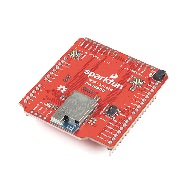
Dialog ULP WiFi DA16200 R3 Shield Hookup Guide
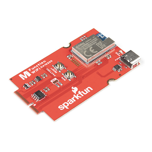
MicroMod WiFi Function Board - DA16200 Hookup Guide
DA16200 Thing Plus Hookup Guide
Serial Communication
Serial Terminal Basics
Connectivity of the Internet of Things
ARM Programming
FreeRTOS and SDK
To understand what is a FreeRTOS and how it is involved in the SDK for the Dialog DA16200 module, users will need to familiarize themselves with the fundamentals of operating systems (OS), schedulers, and real time operating systems (RTOS). In this section, a brief overview of these topics is presented below. However, for a more in-depth introduction to real time operating systems and some of the features of FreeRTOS, please check out the Digi-Key video series on RTOS presented by Shawn Hymel (former SparkFun personality):
Digi-Key video series on RTOS (Source: Youtube)
OS Scheduler
For any operating system (OS), an individual processor core is capable of running only one thread at a time. However, some operating systems implement a scheduler to control its processing resources; where, the scheduler allocates the processing time and priority of tasks executed on the processor's core(s). This allows the OS to create the illusion of running multiple programs simultaneously (i.e. multi-tasking) when the scheduler rapidly switches between the individual processes for each program.
Real Time Operating System (RTOS)
An operating system can be defined by how its scheduler prioritizes program execution. In a real time operating system (RTOS), the scheduler is designed to operate in a deterministic (i.e. predictable) execution pattern. This is ideal for embedded systems, which require a response to events within a specific time frame.
FreeRTOS
FreeRTOS is a prevalent real-time operating system that is distributed freely under the MIT open source license. It includes a kernel and a growing set of IoT libraries, which are designed to be light enough to run on a resource constrained processor; such as a microcontroller. Currently, the project is maintained by Amazon Web Services (AWS).
FreeRTOS was built with an emphasis on reliability and ease of use.
- Within their code, users assign priorities to each task or thread of execution. The kernel then automatically handles all the real time scheduling, inter-task communication, and the timing and synchronization primitives. Therefore, allowing the scheduler to operate in a deterministic manner, executing tasks based on the assigned priority.
- Additional functionality, such as a command console interface, or networking stacks, can then be included with add-on components.
DA16200 FreeRTOS SDK
The DA16200 FreeRTOS SDK is provided and maintained by Renesas. It is a port of FreeRTOS, built specifically to operate on the DA16200 module. Unfortunately, due to the depth of information that can be covered, we won't go into details about the SDK operation beyond basic examples we provide.
- For topics such as interrupt service routines and peripheral pin functions, users should refer to the SDK documentation for the DA16200 module.
- For information related to the RTOS, such as task management, users can refer to the FreeRTOS API documentation.
For more documentation on FreeRTOS and the DA16200 FreeRTOS SDK, please refer to the resources below:
Software Setup
- Windows 10 and Ubuntu 20.04.1 LTS
- Users may need administrative privileges to install some of the following software.
- xPack Project Manager:
- GNU Arm GCC 10.2.1
- Windows: Windows Build Tools
- Eclipse 2020-09
- DA16200 FreeRTOS SDK
- Serial Terminal with Y-Modem support
- Windows: Tera Term (Recommended)
- Linux: minicom (Recommended)
Users should have already familiarized themselves with the DA16200 FreeRTOS Getting Started Guide. While a majority of the information in this section is already covered in the DA16200 FreeRTOS Getting Started Guide, we have included a few additional details specific to the DA16200 boards in our catalog. Below, are a complete set of instructions for users to download, install, and setup the various programs required for the DA16200 FreeRTOS SDK.
Serial-to-UART Driver
Depending on the board and/or adapter being utilized, users will need to install the appropriate driver for their computer to recognize the serial-to-UART chip on their board/adapter. Most of the latest operating systems will recognize serial-to-UART chip on the board and automatically install the required driver.
To manually install the CH340 driver on their computer, users can download it from the WCH website. For more information, check out our How to Install CH340 Drivers Tutorial.
How to Install CH340 Drivers
Terminal Emulator (with Y-Modem)
In order to program their board through the USB-C connection and access the serial debug interface, users will need a serial terminal installed on their computer. We have verified that these emulators, below, support Y-Modem to upload the SDK bootloader and firmware. Users are welcome to use their preferred serial terminal, but we will only provide support with these applications for this tutorial.
For Windows computers, we recommend Tera Term. Please refer to the serial terminal basics tutorial to get started with installing and utilizing Tera Term:
Serial Terminal Basics
This tutorial will show you how to communicate with your serial devices using a variety of terminal emulator applications.On Linux computers, users should install
minicom.language:bash sudo apt install minicom
Once installed, users will need to configure the serial terminal with the following settings for the COM port they are utilizing:
- Baud Rate: 230400 bps
- Data Bits: 8 (8-N-1)
- Parity: None
- Stop Bits: 1
- Flow Control (HW/SW): None
Download the DA16200 FreeRTOS SDK Image
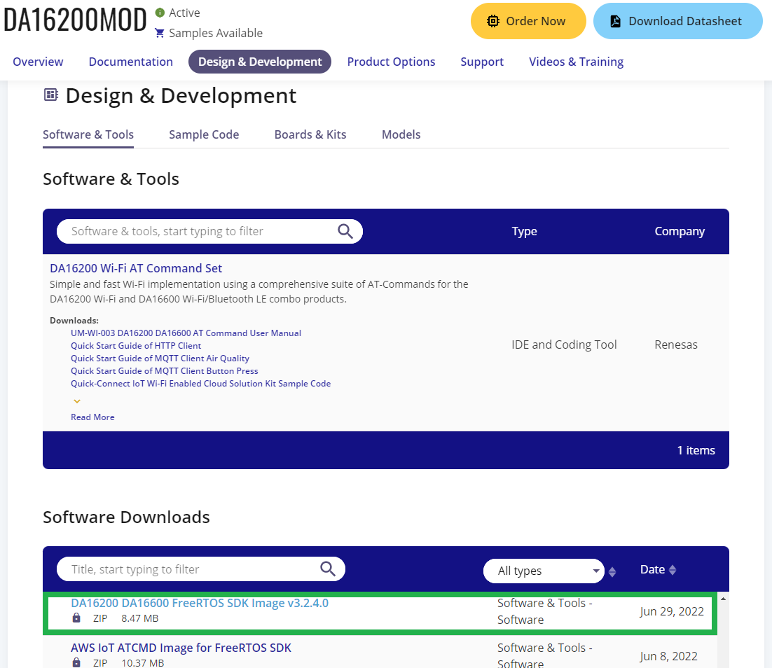
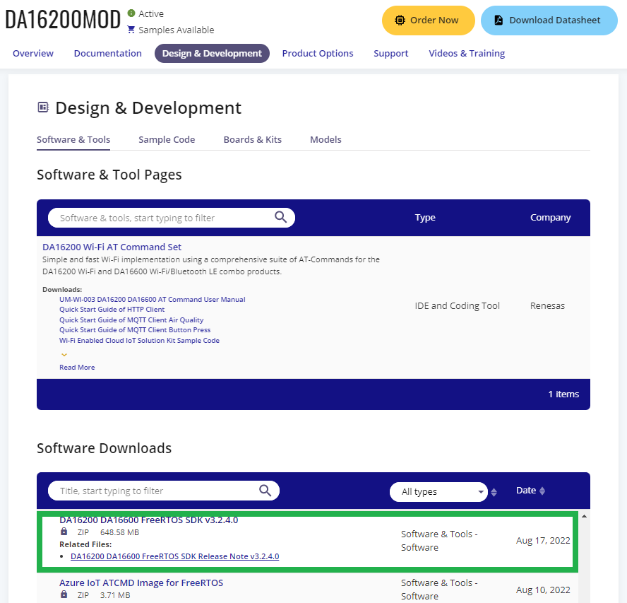
In order to utilize the DA16200 FreeRTOS SDK, users should to program their board with the latest DA16200 FreeRTOS SDK firmware. To download the DA16200 FreeRTOS SDK Image, users will need to register an account first. Then, from the Design & Development tab of the DA16200MOD product page, users can download the:
- DA16200 DA16600 FreeRTOS SDK Image v3.2.4.0 (8.47 MB) 08/17/2022
- There are two firmware images for the DA16200 FreeRTOS SDK:
- FBOOT is the bootloader image which is used to initialize the DA16200 and launch the main firmware.
- File Name:
DA16200_FBOOT-GEN01-01-XXXXXXXXX_W25Q32JW.img - The bootloader image must be the first thing loaded into flash for a new device.
- Since the bootloader image contains SFDP (flash specific) information, the bootloader must be loaded into flash before other images are loaded.
- When the SDK is updated, always load the bootloader image first.
- File Name:
- FRTOS is the main firmware image which includes the RTOS and user applications.
- File Name:
DA16200_FRTOS-GEN01-01-XXXXXXXXX-XXXXXX.img
- File Name:
- FBOOT is the bootloader image which is used to initialize the DA16200 and launch the main firmware.
Download the DA16200 FreeRTOS SDK
C:/dialog_sdk).To download the DA16200 FreeRTOS SDK, users will need to register an account first. Then, from the Design & Development tab of the DA16200MOD product page, users can download the:
- DA16200 DA16600 FreeRTOS SDK v3.2.3.0 (648.58 MB) 08/17/2022
For more information on the content of the DA16200 FreeRTOS SDK (i.e. file organization, API, example applications, etc.), please refer to the DA16200 FreeRTOS SDK Programmer Guide.
xPack Project Manager
Users will need to install the xPack Project Manager (xpm), to install the following xPack development tools required to utilize the SDK. Follow the instructions on the xPack website to install the software.
To install the xPack Project Manager (xpm) through Node.js, open a Windows command line or a Linux terminal and enter the following command:
language:bash
npm install --global xpm@latest
GCC Toolchain
In order to compile the code from the SDK, users will need to install the GNU Arm GCC (v10.2.1) cross compiler.
This development tool can be installed as an xPack package through the xPack Project Manager. Once users have installed the xpm, from the section above, open a Windows command line or a Linux terminal and enter the following command:
language:bash
xpm install --global @xpack-dev-tools/arm-none-eabi-gcc@10.2.1-1.1.2
Windows Build Tools
Windows does not include any build tools (i.e. make) by default; therefore, users should install the Windows Build Tools xPack package.
This development tool can be installed as an xPack package through the xPack Project Manager. Once users have installed the xpm, from the section above, open a Windows command line and enter the following command:
language:bash
xpm install --global @xpack-dev-tools/windows-build-tools
Install and Setup Eclipse
The Eclipse IDE (integrated development environment) is a free and open source development platform that is released under the Eclipse Public License (EPL). The Eclipse IDE will be used to import the DA16200 FreeRTOS SDK into a workspace and build/compile the example projects using xPack development tools.
For more documentation on the Eclipse IDE, please refer to the resources below:
Installation
Installation of the Eclipse IDE is simple:
- Download the installer for the Eclipse IDE. (Users can also download the installation software from the Download or Getting Started pages.)
Run the downloaded executable to launch the Eclipse Installer.
On Linux platforms, use the following commands to extract and execute to Eclipse Installer:
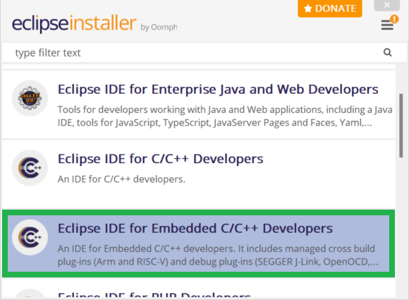
language:bash tar -xvzf eclipse-inst-jre-linux64.tar.gz cd eclipse-installer ./eclipse-inst- Select the Eclipse IDE for Embedded C/C++ Developers from the installation options.
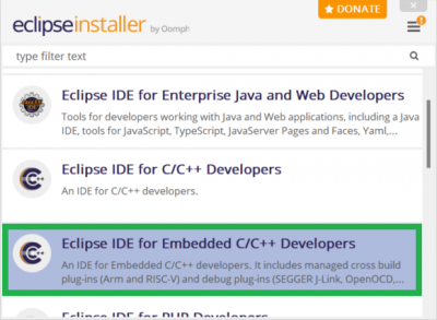 Installation menu from Eclipse Installer. (Click to enlarge)
- Select the program's installation location and accept the software agreements.
Configuration
The first time users launch the Eclipse IDE, they be prompted to select a folder for the program's workspace. However, before users can proceed to working on a project, they will need to setup DA16200 FreeRTOS SDK and link the xPack development tools.
Configure the Development Tools:
In order to build the DA16200 FreeRTOS SDK, users will need to configure the Eclipse IDE and link the necessary development tools.
- To setup the GCC Toolchain, users need to provide the file path to the compiler:
- Open the Window > Preferences dialog box.
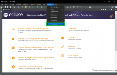 Open the Preferences dialog box from the Window drop down menu. (Click to enlarge)
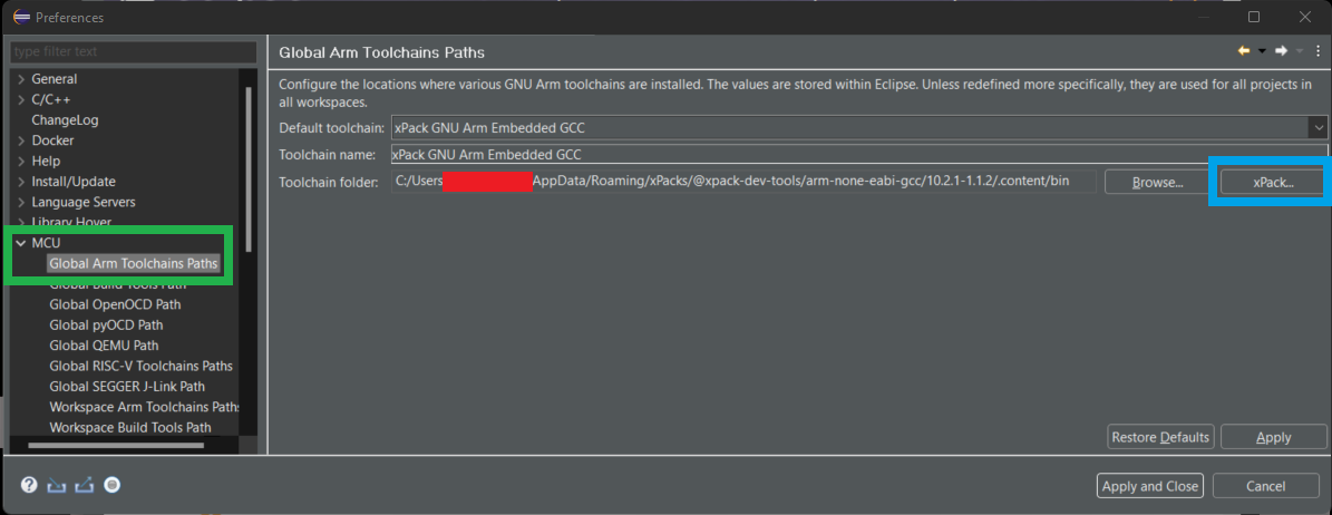
 - In the preferences dialog, select MCU > Global Arm Toolchain Paths and verify the
Toolchainfolder points to the where the GNU Arm GCC 10.2.1 toolchain is installed.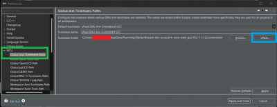 Link the compiler to the GCC toolchain. (Click to enlarge)
- If the GNU Arm GCC 10.2.1 xPack was installed, users should find it with a file path similar to the following:
C:/Users/<username>/AppData/Roaming/xPacks/@xpack-dev-tools/arm-none-eabi-gcc/<gcc version>/.content/bin
- If the toolchain folder is empty or incorrect, press the xPack button and select the correct Version.
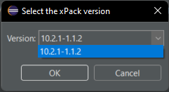 Verify the xPack version. (Click to enlarge)
- If the GNU Arm GCC 10.2.1 xPack was installed, users should find it with a file path similar to the following:
- Open the Window > Preferences dialog box.
- To setup the build tool (i.e.
make; only on Windows), users need to provide the file path to the build tool:- Open the Window > Preferences dialog box.
Open the Preferences dialog box from the Windows drop down menu. (Click to enlarge)
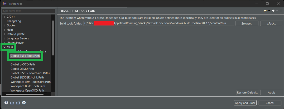
- In the preferences dialog, check the MCU > Global Build Tools path and verify it points to where the Windows Build Tools xPack has been installed.
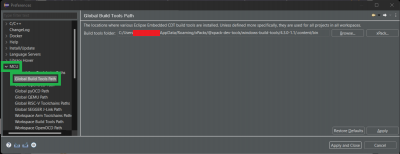 Link the Windows build tools to the Eclipse IDE. (Click to enlarge)
- If the Windows Build Tools xPack was installed, users should find it with a file path similar to the following:
C:/Users/<username>/AppData/Roaming/xPacks/@xpack-dev-tools/windows-build-tools/<Window Build Tools version>/.content/bin
- If the Windows Build Tools xPack was installed, users should find it with a file path similar to the following:
- Open the Window > Preferences dialog box.

Import the DA16200 FreeRTOS SDK:
<sdk_root_directory> path length must be less than 70 characters.
Users will also need to import the DA16200 FreeRTOS SDK into the Eclipse IDE:
- Download the DA16200 FreeRTOS SDK. (Users will need to register an account.)
- From the Design & Development tab of the DA16200MOD product page, users can download the DA16200 FreeRTOS SDK.
 Download the latest DA16200 FreeRTOS SDK from the DA16200MOD product page. (Click to enlarge)
- From the Design & Development tab of the DA16200MOD product page, users can download the DA16200 FreeRTOS SDK.
Extract the SDK zip file; this directory of this folder will be known as the
<sdk_root_directory>.- The Windows operating system has a path length limitation of 260 characters. Therefore, the
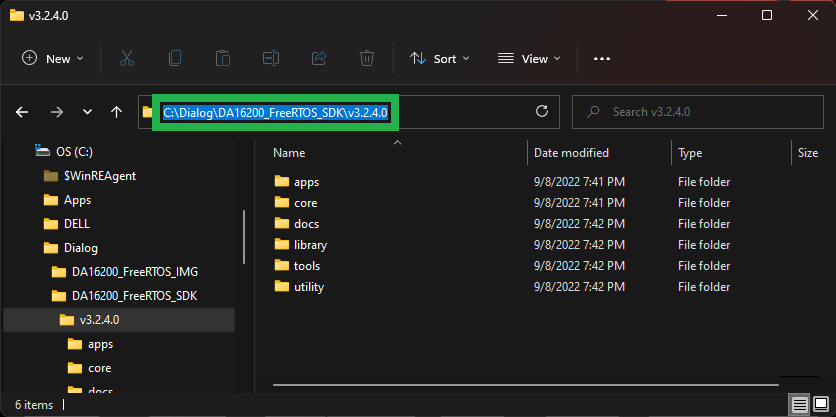
<sdk_root_directory>path length must be less than 70 characters.- We recommended that users extract the SDK into the root directory of a disk drive and rename the folder to shorten the file path length (i.e.
C:/dialog_sdk).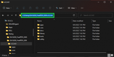 An example of a shortened
<sdk_root_directory>file path. (Click to enlarge)
- We recommended that users extract the SDK into the root directory of a disk drive and rename the folder to shorten the file path length (i.e.
For Linux systems, certain files used during the build process need to be set as executable. After extracting the SDK files, the
<sdk_root_directory>/tools/utilfile permissions must be changed by running theset_linux_perm.shscript in that directory:language:bash cd <sdk_root_diretory>/tools/util chmod 755 set_linux_perm.sh sh ./set_linux_perm.sh
- The Windows operating system has a path length limitation of 260 characters. Therefore, the
- To setup the SDK in Eclipse, the top-level project contained in the
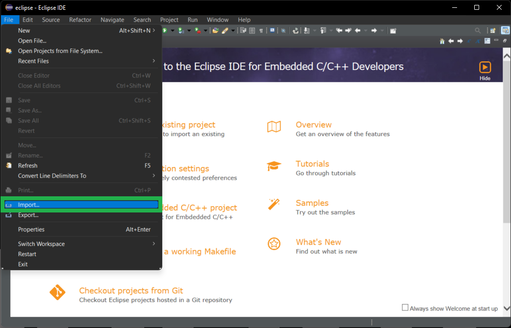
<sdk_root_directory>should be imported. This will provide a view into the full SDK source code and will set up the launch and debug configurations required by the SDK.- Under the
Filemenu selectImport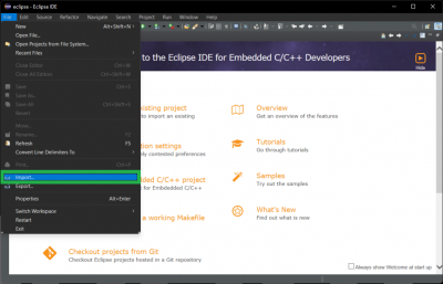 Open the Import dialog box from the Files drop down menu. (Click to enlarge)
 - In the Import dialog box, select General > Existing Projects into Workspace and press the Next button.
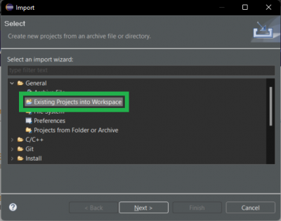 Select the Existing Projects into Workspace option. (Click to enlarge)
 - In the Import dialog box, select the Select root directory option and press the Browse button.
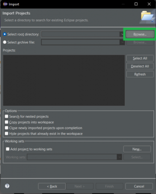 Select the Select root directory option. (Click to enlarge)
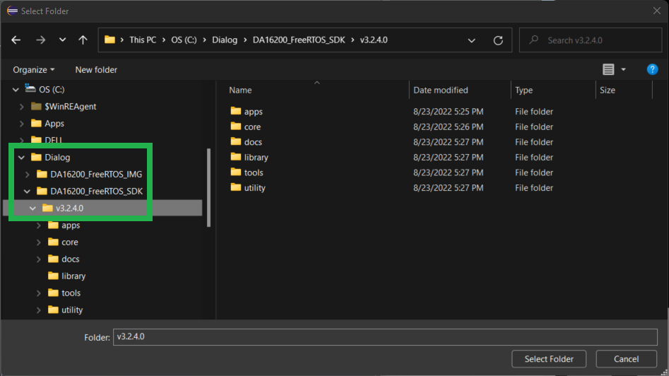
 - Use the file manager to navigate to the
<sdk_root_directory>directory and then press the Select Folder button.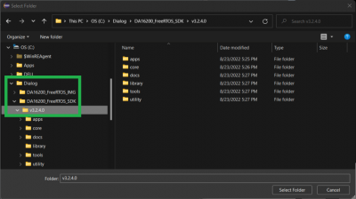 Select the folder of the the
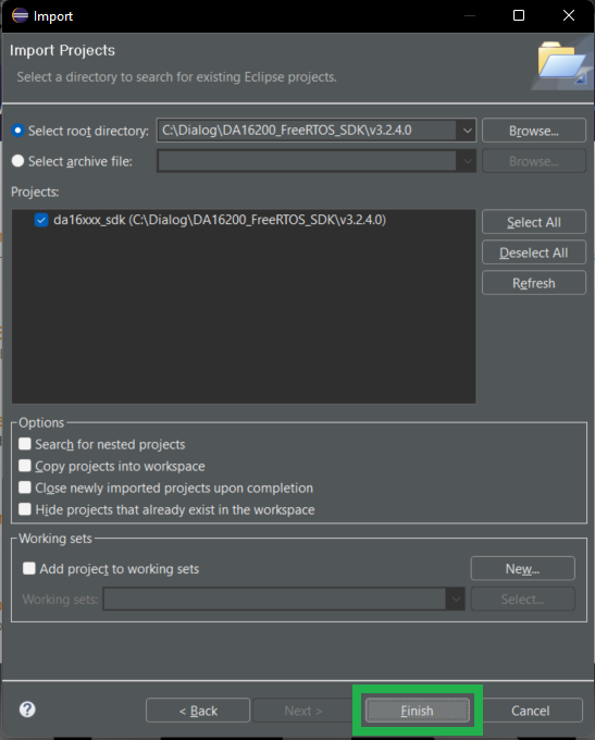
<sdk_root_directory>. (Click to enlarge) - A project should appear in the Projects list which matches the name of the
<sdk_root_directory>. Select that project and then press the Finish button. Select the project from the list. (Click to enlarge)
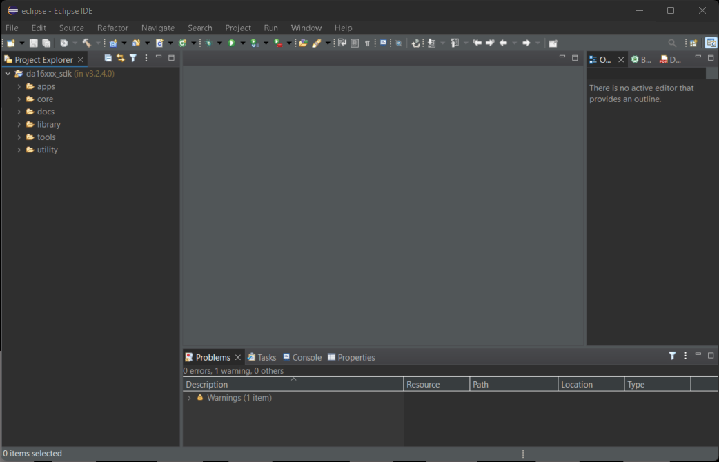
 - The project will appear in the Eclipse Project Explorer.
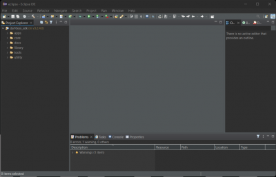 The DA16200 FreeRTOS SDK imported into the Eclipse Project Explorer. (Click to enlarge)
- Under the


Segger J-Link Software
Note: In order to program and debug the DA16200MOD, a J-Link Lite (or higher) programmer is required. Users may also be interested in these J-Link programmers and accessories.
J-Link EDU Mini Programmer
PGM-15345
J-Link BASE Compact Programmer
PGM-15347
JTAG 20 Pin 0.1 In. To 10 Pin 0.05 In. Adapter
PGM-18421For a comparison of the different J-Link programmer models, please refer to the Segger website.
Below are the minimum requirements to setup the J-Link programmer to be used in the Eclipse IDE for the DA16200 FreeRTOS SDK:
- Eclipse 2021-06 (4.20.0) or later
- J-Link software V6.98 or later
In order to use the J-Link flash loader with the DA16200MOD, users will need to add it to the J-Link software:
- With the J-Link software already installed, find the installation directory and locate the
JLinkDevices.xmlfile.- Example:
C:\Program Files (x86)\SEGGER\JLink\JLinkDevices.xml
- Example:
Open
JLinkDevices.xmlin a text editor and add device entries for the DA16200 to the<DataBase>section as follows:language:xml <DataBase> <!-- -> <!-- Dialog Semiconductor -> <!-- -> <Device> <ChipInfo Vendor="Dialog Semiconductor" Name="DA16200_W25Q32JW" Core="JLINK_CORE_CORTEX_M4" WorkRAMAddr="0x80000" WorkRAMSize="0x00040000" /> <FlashBankInfo Name="QSPI Flash" BaseAddr="0x100000" MaxSize="0x400000" Loader="Devices/Dialog/DA16200_W25Q32JW.elf" LoaderType="FLASH_ALGO_TYPE_OPEN" /> </Device> <Device> <ChipInfo Vendor="Dialog Semiconductor" Name="DA16200.SeggerES.4MB" Core="JLINK_CORE_CORTEX_M4" WorkRAMAddr="0x83000" WorkRAMSize="0x00020000" /> <FlashBankInfo Name="QSPI Flash" BaseAddr="0x10000000" MaxSize="0x400000" Loader="Devices/Dialog/ES_DA16200_4MB.elf" LoaderType="FLASH_ALGO_TYPE_OPEN" /> </Device> <Device> <ChipInfo Vendor="Dialog Semiconductor" Name="DA16200.SeggerES.2MB" Core="JLINK_CORE_CORTEX_M4" WorkRAMAddr="0x83000" WorkRAMSize="0x00020000" /> <FlashBankInfo Name="QSPI Flash" BaseAddr="0x10000000" MaxSize="0x200000" Loader="Devices/Dialog/ES_DA16200_2MB.elf" LoaderType="FLASH_ALGO_TYPE_OPEN" /> </Device> <Device> <ChipInfo Vendor="Dialog Semiconductor" Name="DA16200.eclipse.4MB" Core="JLINK_CORE_CORTEX_M4" WorkRAMAddr="0x83000" WorkRAMSize="0x00020000" /> <FlashBankInfo Name="QSPI Flash" BaseAddr="0x10000000" MaxSize="0x400000" Loader="Devices/Dialog/DA16200_4MB.elf" LoaderType="FLASH_ALGO_TYPE_OPEN" /> </Device> <Device> <ChipInfo Vendor="Dialog Semiconductor" Name="DA16200.eclipse.2MB" Core="JLINK_CORE_CORTEX_M4" WorkRAMAddr="0x83000" WorkRAMSize="0x00020000" /> <FlashBankInfo Name="QSPI Flash" BaseAddr="0x10000000" MaxSize="0x200000" Loader="Devices/Dialog/DA16200_2MB.elf" LoaderType="FLASH_ALGO_TYPE_OPEN" /> </Device> </DataBase>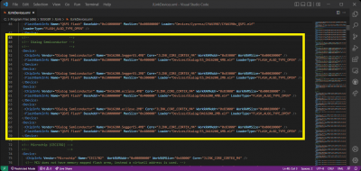 Device entries added to the
JLinkDevices.xmlfile. (Click to enlarge)- Copy the flash loader files from the
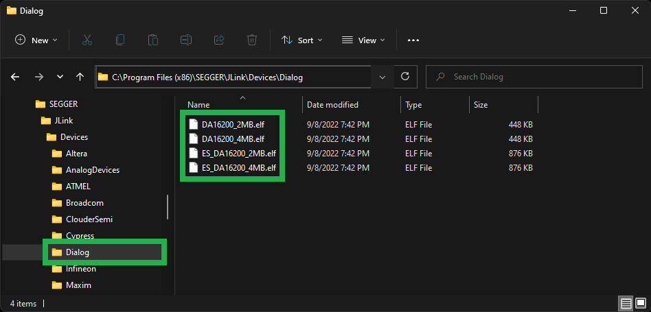
<sdk_root_directory>/utility/j-link/scripts/flashloader/Devices/Dialogdirectory into the directory where theJLinkDevices.xmlis located. Flash loader files in the
C:\Program Files (x86)\SEGGER\JLink\Devices\Dialogdirectory. (Click to enlarge) - Configure the file path of the J-Link software in the Eclipse IDE
- In the Eclipse IDE, open the Window > Preferences dialog box.
Open the Preferences dialog box from the Window drop down menu in the Eclipse IDE. (Click to enlarge)
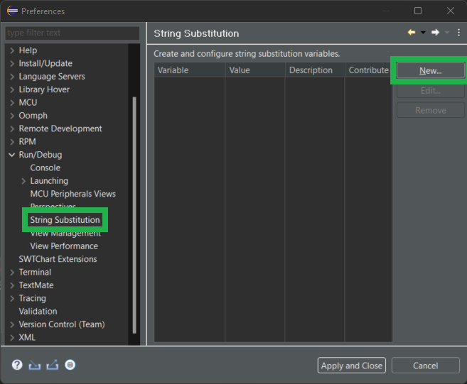
- In the preferences dialog box, select Run/Debug > String Substitution and press the New button.
 Create a new variable. (Click to enlarge)
 - Enter
jlink_pathas the variable name and set the value as the file path to the J-Link software:C:\Program Files (x86)\SEGGER\JLinkC:\Users\<USER>\AppData\Roaming\SEGGER\JLinkDevices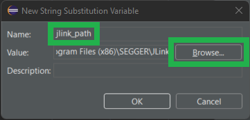 Add the
jlink_pathvariable linking to the J-Link software. (Click to enlarge)
- Click the OK and then the Apply and Close buttons to save the setting.
- In the Eclipse IDE, open the Window > Preferences dialog box.

Note: If users are having trouble locating the flash loader files or modifying the JLinkDevices.xml file, please feel free to utilize this archived version of the files. These files are meant to be used with:
- DA16200 FreeRTOS SDK v3.2.4.0
- J-Link v7.80b
Follow the instructions below, to utilize the archived files:
- Extract the archived files from the
j-link_files.zipzip folder. - Replace the
JLinkDevices.xmlfile in theC:\Program Files (x86)\SEGGER\JLinkdirectory with the extracted file. - Add the flash loader files by moving the extracted
Dialogfolder into theC:\Program Files (x86)\SEGGER\JLink\Devicesdirectory.
Once the users have linked the J-Link software to the Eclipse IDE, they will need to import the j-link project to provide an absolute path for the SDK scripts to use. The project can be imported using the Eclipse Project Explorer by navigating to the <sdk_top_directory>/utility/j-link/project/ and then right click on that directory and select Import as Project.
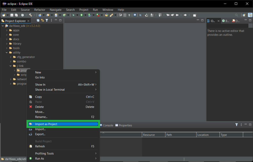
For more information on utilizing J-Link with the DA16200 FreeRTOS SDK, please refer to the instructions in the <sdk_root_directory>\utility\j-link\scripts\ReadMe.txt file.
Serial Debug Interface
Note: This tutorial assumes that users are already familiar with serial terminals and their use. However, for those of who have never heard of them before, feel free to check our tutorials below:
- Depending on the board and/or adapter being utilized, users may need to install the appropriate driver for their computer to recognize the serial-to-UART chip on their board/adapter.
How to Install CH340 Drivers
How to install CH340 drivers (if you need them) on Windows, Mac OS X, and Linux. - Users will also need a serial terminal installed on their computer to access the serial debug interface.
The serial terminal should be configured with the following settings:
- Baud Rate: 230400 bps
- Data Bits: 8 (8-N-1)
- Parity: None
- Stop Bits: 1
- Flow Control (HW/SW): None
Serial Terminal Basics
This tutorial will show you how to communicate with your serial devices using a variety of terminal emulator applications.
The DA16200MOD can be controlled through the serial debug interface with the available console commands. The console is accessed by connecting the UART0 interface of the DA16200MOD module to a serial terminal on a computer.
- To operate various functions of the DA16200MOD module, please refer to Appendix B of the DA16200 FreeRTOS Getting Started Guide for a full list of the available debug interface commands.
- For examples of how to utilize the serial debug interface, please refer to sections 4.4 - 4.6 and section 6 of the DA16200 FreeRTOS Getting Started Guide.
- Section 4.6 - WiFi Provisioning
- Section 6.3 - Throughput Test
- Section 6.4 - Dynamic Power Management (DPM) Setup
Update SDK Firmware
Before proceeding further, users will need to update the firmware for the DA16200MOD.
- There are two firmware images for the DA16200:
- FBOOT is the bootloader image which is used to initialize the DA16200 and launch the main firmware.
- File Name:
DA16200_FBOOT-GEN01-01-XXXXXXXXX_W25Q32JW.img - The bootloader image must be the first thing loaded into flash for a new device.
- Since the bootloader image contains SFDP (flash specific) information, the bootloader must be loaded into flash before other images are loaded.
- When the SDK is updated, always load the bootloader image first.
- File Name:
- FRTOS is the main firmware image which includes the RTOS and user applications.
- File Name:
DA16200_FRTOS-GEN01-01-XXXXXXXXX-XXXXXX.img - There are two slots in the SFlash memory to upload the main firmware image:
RTOS #0begins at0x023000RTOS #1begins at0x1e2000
- File Name:
- FBOOT is the bootloader image which is used to initialize the DA16200 and launch the main firmware.
- The DA16200 SDK can be used to build the firmware images for a specific example project from the DA16200 FreeRTOS SDK.
- Prebuilt versions of the latest firmware for DA16200 can be downloaded from the Renesas product page.
- Users can download the latest images from the Software Downloads section of the Design & Development tab. The firmware images should be named:
DA16200 DA16600 FreeRTOS SDK Image <version>. (Users will need an account to download these files.) Download the latest DA16200 FreeRTOS SDK firmware from the DA16200MOD product page. (Click to enlarge)
- Users can download the latest images from the Software Downloads section of the Design & Development tab. The firmware images should be named:
To update the firmware on the DA16200MOD, users will need to connect to the module to a computer through the serial debug interface. From a serial terminal, users will use Y-Modem to upload the updated SDK bootloader and firmware images to the DA16200MOD.
To update the firmware images on the DA16200:
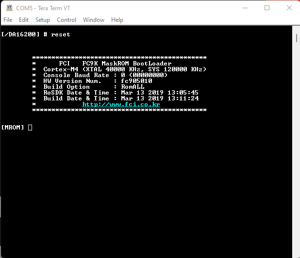
- In the serial terminal, at the
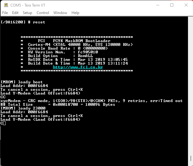
[/DA16xxx]prompt, enterresetto access to the MaskROM mode.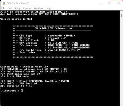 Splash screen and intial prompt for the serial debug interface. (Click to enlarge)
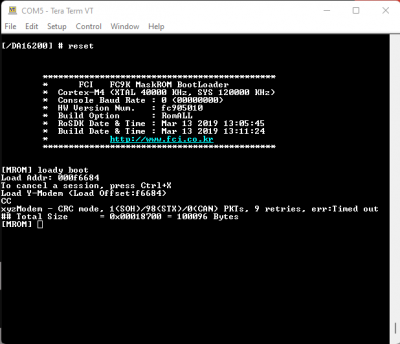
 - At the
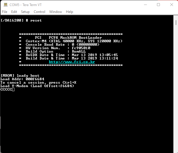
[MROM]prompt, use theloadycommand to upload one of the firmware images. MROM command mode. (Click to enlarge)
- For the second bootloader firmware image (
FBOOT), use theloady bootorloady 0command. Command to upload the
FBOOTimage. (Click to enlarge) - For the main firmware image (
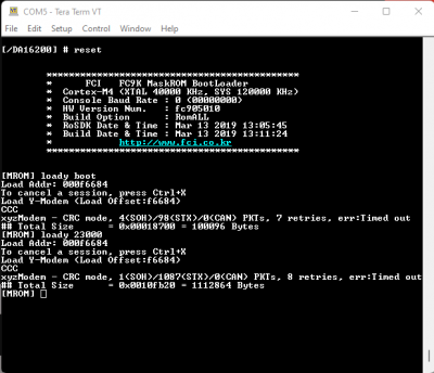
FRTOS), use theloady 23000command (forRTOS #0). Command mode to upload the
FRTOSimage. (Click to enlarge)
- For the second bootloader firmware image (
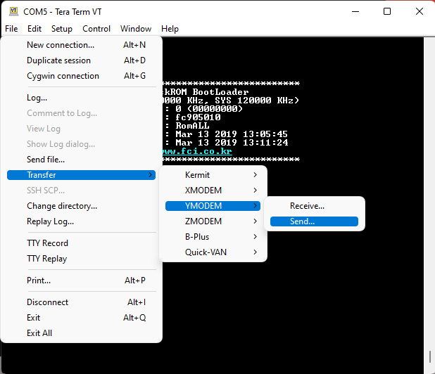
- In the terminal emulation program, start the Y-Modem file transfer:
- For Windows Tera Term:
- From the File menu, select Transfer > YMODEM > Send.
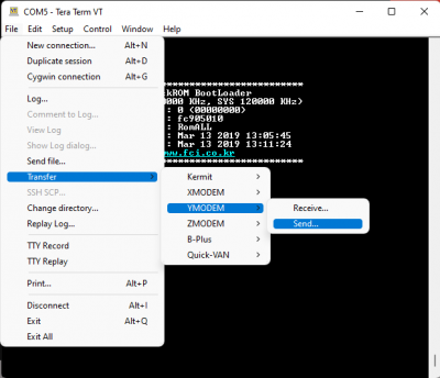 Y-Modem file transfer. (Click to enlarge)
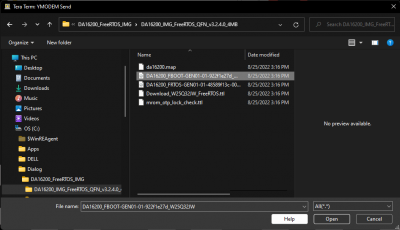
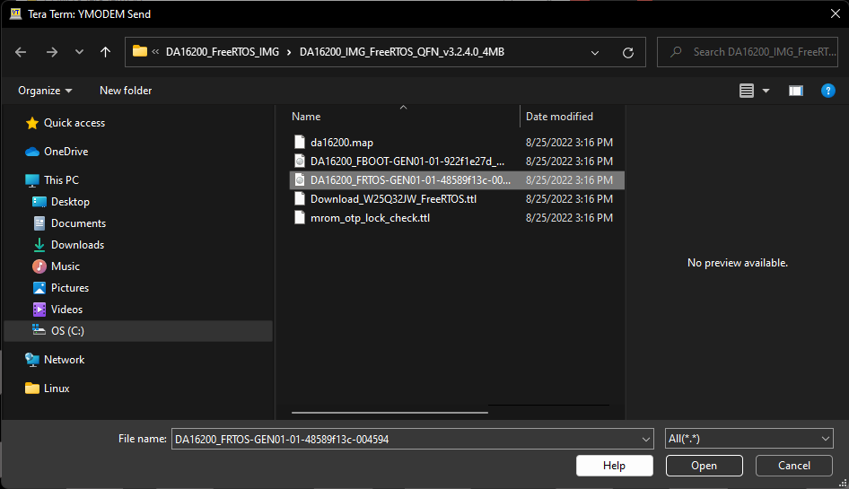
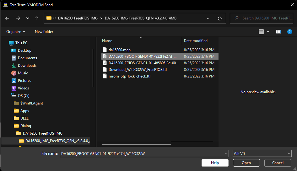
 - Navigate to where the firmware image is stored, choose the required firmware image and start the download.
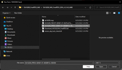 Select firmware image. (Click to enlarge)
- From the File menu, select Transfer > YMODEM > Send.
- For Linux
minicom:- Press Ctrl+A+S and select
ymodemfrom the menu. - Navigate to where the firmware image is stored, choose the required firmware image and start the download.
 Select firmware image. (Click to enlarge)
- Press Ctrl+A+S and select
- For Windows Tera Term:
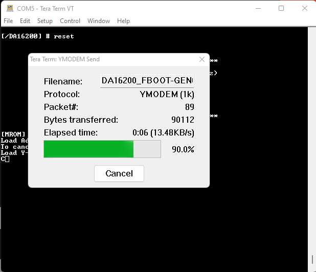
After the transfer completes, the total size is displayed.

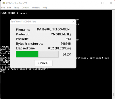
Y-Modem file transfer completed. (Click to enlarge) - When updating the firmware images for a new version of the SDK, both the second bootloader firmware image (
FBOOT) and the main firmware image (FRTOS) must be uploaded.- When uploading a main firmware image (
FRTOS) for a project built with the SDK (no version update), it isn't necessary to upload the second bootloader firmware image (FBOOT).
- When uploading a main firmware image (
- After all firmware images have been uploaded to the DA16200MOD, use the
bootcommand at the[MROM]prompt to restart the firmware. - After the firmware reboots, at the
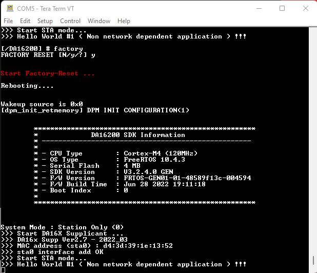
[/DA16200]prompt, users can return the DA16200MOD to a factory configuration state with thefactorycommand.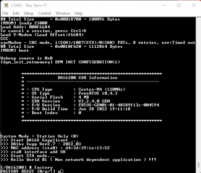 Factory reset command. (Click to enlarge)
- When prompted, enter
yto confirm. Reboot after a factory reset. (Click to enlarge)
- When prompted, enter
- In the serial terminal, at the
- With TeraTerm (Windows only), users can also upload the SDK bootloader and firmware using the TeraTerm script.
- Tera Term script is only available with the prebuilt versions of firmware downloaded from the Renesas product page. (The script is not generated with the images from the DA16200 FreeRTOS SDK project builds.)
- Once terra term is running and connected to the DA16200MOD, open the Control menu and select Macro. When the Macro file selection window opens, navigate to the directory where the firmware images are stored and select the
*.ttlfile. Uploading the SDK bootloader and firmware using the TeraTerm script. (Click to enlarge)


Upload New Project Firmware
The process for uploading new firmware for an SDK project build is a similar method to updating the SDK firmware. Users will need to connect to the module to a computer through the serial debug interface. From a serial terminal, users will use Y-Modem to upload the new firmware image to the DA16200MOD.
- To update the firmware images on the DA16200:
- In the serial terminal, at the
[/DA16xxx]prompt, enterresetto access to the MaskROM mode. Splash screen and intial prompt for the serial debug interface. (Click to enlarge) - At the
[MROM]prompt, use theloadycommand to upload one of the firmware images.- For the main firmware image (
FRTOS), use theloady 23000command forRTOS #0. - When uploading a main firmware image (
FRTOS) for a project built with the SDK (no version update), it isn't necessary to upload the second bootloader firmware image (FBOOT). Command mode to upload theFRTOSimage. (Click to enlarge)
- For the main firmware image (
- In the terminal emulation program, start the Y-Modem file transfer:
- For Windows Tera Term:
- From the File menu, select Transfer > YMODEM > Send.
Y-Modem file transfer. (Click to enlarge)
- Navigate to where the firmware image is stored, choose the required firmware image and start the download.
- From the File menu, select Transfer > YMODEM > Send.
- For Linux
minicom:- Press Ctrl+A+S and select
ymodemfrom the menu. - Navigate to where the firmware image is stored, choose the required firmware image and start the download.
- Press Ctrl+A+S and select
- For Windows Tera Term:
- After the transfer completes, the total size is displayed. Use the
bootcommand at the[MROM]prompt to restart the firmware.
- In the serial terminal, at the
Select the Boot Index
There are two slots, in which the main firmware image FRTOS can be stored in the SFLASH memory. These locations are at RTOS #0 (0x23000) and RTOS #1 (0x1e2000). Through the serial debug interface, users can specify which firmware image that the board boots up with.
- From the command console, the boot index can be changed using the
boot_idxcommandboot_idx 0- setsRTOS #0as the firmware to bootboot_idx 1- setsRTOS #1as the firmware to boot
- After running the
boot_idxcommand, run therebootcommand to boot the firmware that was selected.
Erase Firmware
Users can erase the firmware from the SFLASH memory. This can be performed through the Net command mode.
- From the
[/DA16200] #prompt, enternetto enter the NET command mode. - From the
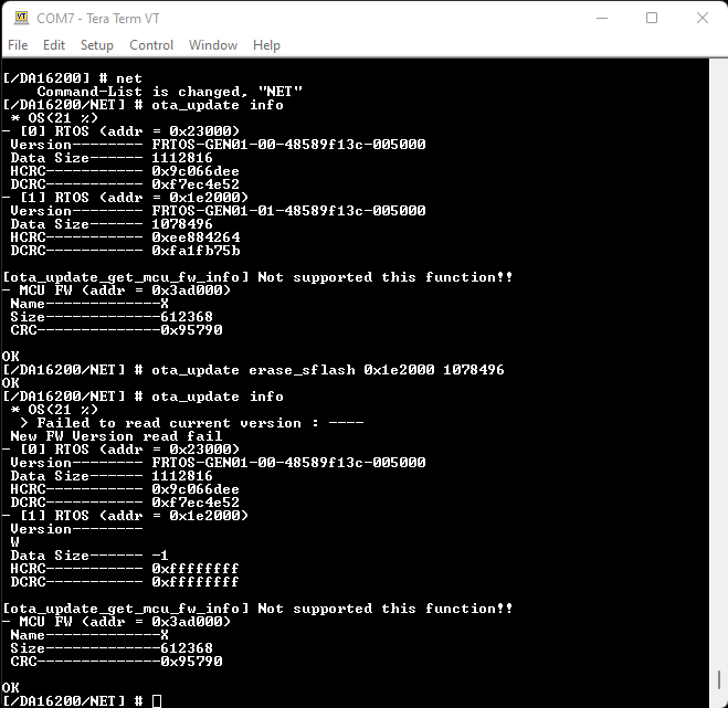
[/DA16200/NET] #prompt, enter theota_update infocommand to display the firmware information from the SFLASH memory - Users can then use the
ota_update erase_sflash <start> <size>command to erase a section of the 4MB SFLASH memory.- Example: To remove the firmware operating in the
RTOS #1section (0x1e2000) with 1078496 bytes of memory, users will use the commandota_update erase_sflash 0x1e2000 1078496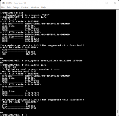 Erasing the firmware from the SFLASH memory for
RTOS #1. (Click to enlarge)
- Example: To remove the firmware operating in the
WiFi Provisioning
To configure the WiFi connection of the DA16200 Thing Plus, follow the instructions below:
- From the
[/DA16200] #prompt, entersetup. - Users will then be prompted
Stop all services for the setting. Are you sure ? [Yes/No] :.- Select yes, by returning
y.
- Select yes, by returning
- After, country code list will be displayed and users will be prompted for their country code.
- Users that live in the USA should enter
usfor their country code.
- Users that live in the USA should enter
- Users will then be prompted to select a WiFi mode.
- Select
1to configure the DA16200 Thing Plus for station mode.
- Select
- A list of available networks will then be displayed and users will be prompted to select an option.
- Users should enter the number of the network, which they would like to use.
- Users will be prompted if they want to set advanced WiFi configuration.
- Enter
nto skip this step.
- Enter
- The WiFi connection settings will be displayed and users will be asked to confirm the configuration.
- If the settings are correct, enter
yto confirm the configuration.
- If the settings are correct, enter
- Users will be asked to select a connection type.
- Enter
ato select an automatic DHCP IP address.
- Enter
- Users will be prompted to confirm the configuration.
- Enter
yto confirm the configuration.
- Enter
- Lastly, users will be prompted about the
SNTP ClientandDialog DPM (Dynamic Power Management).- Enter
nfor both of these options.
- Enter
Once completed, the DA16200 will automatically reboot. After the splash screen, users should see a statement declaring that the board is in station mode (System Mode : Station Only (0)), which is eventually followed by a print out of information about the WiFi connection.
Build an Example Project
Each of the example project directories contain a folder structure, which includes a project folder with the DA16200 (or DA16600) target folder(s).
Directory in the Eclipse Project Explorer. (Click to enlarge)
GPIO example application contains both the DA16200 and DA16600 target folders in the example's projects folder:
/apps/common/examples/Peripheral/GPIO/projects/da16200 /apps/common/examples/Peripheral/GPIO/projects/da16600
Import a Project
To build an example application (or project), users must import them into the Eclipse Project Explorer. Navigate to the specific example project directory, right-click on the DA16200 folder in the project directory, and then select Import as Project.
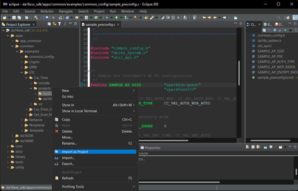
DA16200) folder of the example's projects folder. (Click to enlarge) Build a Project
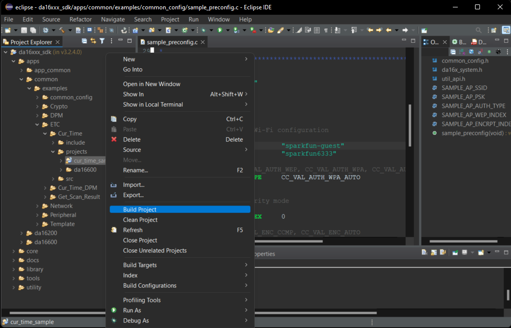
Once the target project is imported, it will appear in the Eclipse Project Explorer. To build the project, right-click on the imported project folder and select Build Project.
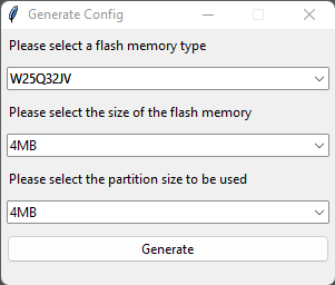
Initial Build
The first time a build process is performed in the SDK, a Generate Configuration window will be displayed automatically to select the flash memory type. Users will need to select the flash memory type and press the Generate button to create the appropriate flash configuration file required to build the firmware.
- If the pop-up window is closed without selecting and generating a configuration file, a warning pop-up is displayed.
- A flash configuration file is required to build the firmware, so the step cannot be skipped.
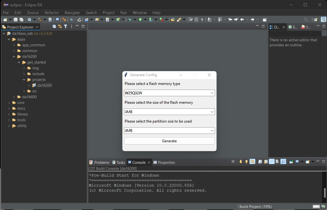
For the DA16200MOD, users will need to select:
- Flash Memory Type:
W25Q32JV - Size of the Flash Memory:
4MB - Partition Size:
4MB
Project - Firmware Images
While the project builds, the following output is displayed in the Eclipse IDE's Console window:
Once complete, there are two firmware images that are generated:
- FBOOT -
DA16200_FBOOT-GEN01-01-XXXXXXXXX_W25Q32JW.img - FRTOS -
DA16200_FRTOS-GEN01-01-XXXXXXXXX-XXXXXX.img
The files are stored in the <sdk_root_directory>/<project_path>/img/ directory.
FBOOTis the bootloader image which is used to initialize the DA16200 and launch the main firmware.- The bootloader image must be the first thing loaded into flash for a new device.
- Since the bootloader image contains SFDP (flash specific) information, the bootloader must be loaded into flash before other images are loaded.
- When the SDK is updated, always load the bootloader image first.
FRTOSis the main firmware image which includes the RTOS and user applications.
Configure the WiFi Connection
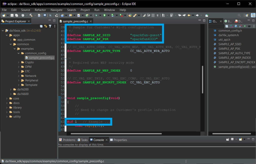
To configure the settings of the WiFi connection, users will need to modify the sample_preconfig.c file of the SDK from the apps > common > examples > common_config directory.
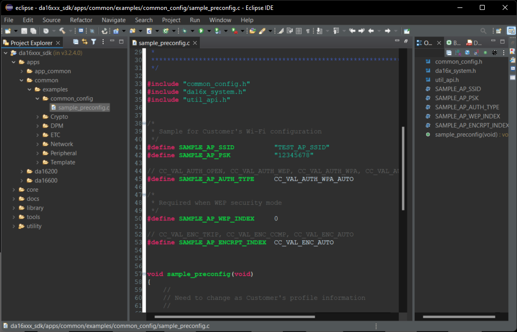
sample_preconfig.c WiFi configuration file for the DA16200 FreeRTOS SDK. (Click to enlarge) Users will need to modify the following lines in the file to configure and enable the WiFi connection of the board:
- Line 41 -
#define SAMPLE_AP_SSID "sparkfun-guest" - Line 42 -
#define SAMPLE_AP_PSK "sparkfun6333" - Line 63 -
#if 1 // Example ...
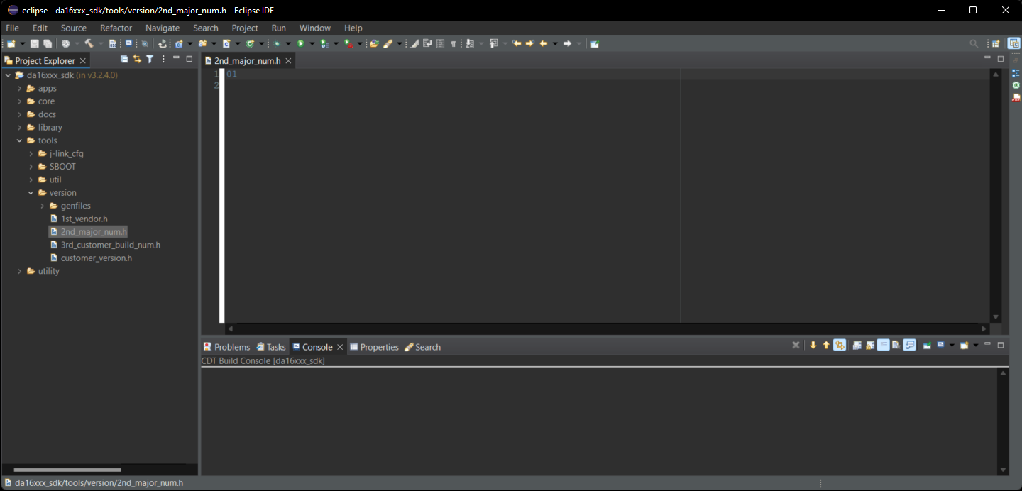
Modify the Build Version
To configure the settings of the build version, users can modify the 2nd_major_number.c file of the SDK from the tools > version directory.
Programming and Debugging
There are two primary methods to update the main firmware (FRTOS) image, with Y-Modem through the serial debug interface or with a J-Link programmer (debugging probe).
Serial Terminal (Y-Modem)
Before proceeding further, users will need to update the firmware for the DA16200MOD.
- There are two firmware images for the DA16200 FreeRTOS SDK:
- FBOOT is the bootloader image which is used to initialize the DA16200 and launch the main firmware.
- File Name:
DA16200_FBOOT-GEN01-01-XXXXXXXXX_W25Q32JW.img - The bootloader image must be the first thing loaded into flash for a new device.
- Since the bootloader image contains SFDP (flash specific) information, the bootloader must be loaded into flash before other images are loaded.
- When the SDK is updated, always load the bootloader image first.
- File Name:
- FRTOS is the main firmware image which includes the RTOS and user applications.
- File Name:
DA16200_FRTOS-GEN01-01-XXXXXXXXX-XXXXXX.img
- File Name:
- FBOOT is the bootloader image which is used to initialize the DA16200 and launch the main firmware.
- The DA16200 SDK can be used to build the firmware images for a specific example project from the DA16200 FreeRTOS SDK.
To update the firmware on the DA16200MOD, users will need to connect to the module to a computer through the serial debug interface. From a serial terminal, users will need to use Y-Modem to upload the updated SDK bootloader and firmware images to the DA16200MOD.
Upload New Project Firmware
The process for uploading new firmware for an SDK project build is a similar method to updating the SDK firmware. Users will need to connect to the module to a computer through the serial debug interface. From a serial terminal, users will use Y-Modem to upload the new firmware image to the DA16200MOD.
- To update the firmware images on the DA16200:
- In the serial terminal, at the
[/DA16xxx]prompt, enterresetto access to the MaskROM mode. Splash screen and intial prompt for the serial debug interface. (Click to enlarge) - At the
[MROM]prompt, use theloadycommand to upload one of the firmware images.- For the main firmware image (
FRTOS), use theloady 23000command forRTOS #0. - When uploading a main firmware image (
FRTOS) for a project built with the SDK (no version update), it isn't necessary to upload the second bootloader firmware image (FBOOT). Command mode to upload theFRTOSimage. (Click to enlarge)
- For the main firmware image (
- In the terminal emulation program, start the Y-Modem file transfer:
- For Windows Tera Term:
- From the File menu, select Transfer > YMODEM > Send.
Y-Modem file transfer. (Click to enlarge)
- Navigate to where the firmware image is stored, choose the required firmware image and start the download.
- From the File menu, select Transfer > YMODEM > Send.
- For Linux
minicom:- Press Ctrl+A+S and select
ymodemfrom the menu. - Navigate to where the firmware image is stored, choose the required firmware image and start the download.
- Press Ctrl+A+S and select
- For Windows Tera Term:
- After the transfer completes, the total size is displayed. Use the
bootcommand at the[MROM]prompt to restart the firmware.
- In the serial terminal, at the
J-Link Software
Hardware Note: In order to program and debug the DA16200MOD, a J-Link Lite (or higher) programmer (i.e. debug probe) is required. Users may need to solder on a JTAG header to connect a J-Link programmer to their board; an adapter may also be required.
Below are a few examples of J-Link programmers and JTAG accessories from our catalog:
J-Link EDU Mini Programmer
PGM-15345
J-Link BASE Compact Programmer
PGM-15347
JTAG 20 Pin 0.1 In. To 10 Pin 0.05 In. Adapter
PGM-18421For a comparison of the different J-Link programmer models, please refer to the Segger website.
Software Note: Below are the minimum requirements to setup the J-Link programmer to be used in the Eclipse IDE for the DA16200 FreeRTOS SDK:
-
Eclipse 2021-06 (4.20.0) or later
Download the latest version of the Eclipse IDE -
J-Link software V6.98 or later
Download the latest version of J-Link
Program
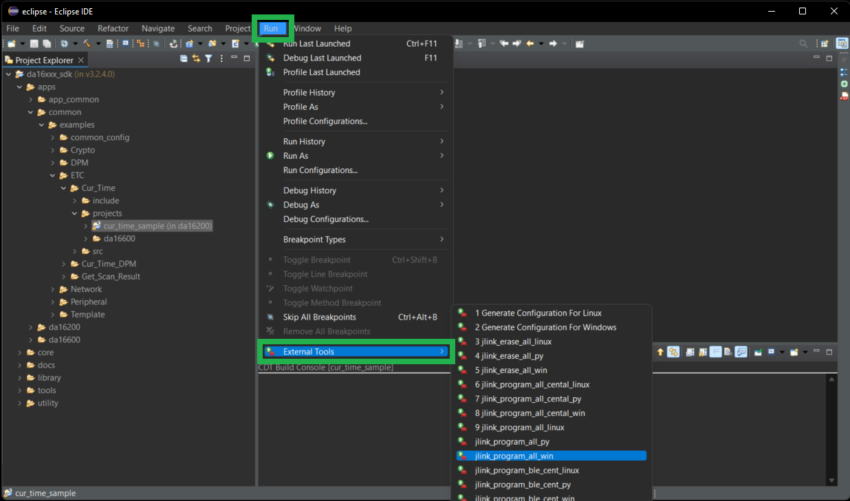
To program binaries into a target device, users will need to execute the program_all_jtag_win script for Windows or the program_all_jtag_linux script for Linux in the External Tools menu.
- Select the project to be programmed in the Project Explorer.
- Under the
Runmenu, selectExternal Tools(i.e. Run > External Tools). - Select
program_all_jtag_winorprogram_all_jtag_linux.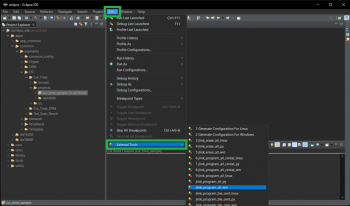 Select script to program with J-Link. (Click to enlarge)
The following scripts are available in the DA16200 FreeRTOS SDK:
- Erase all contents of the flash memory:
erase_all_jtag_winerase_all_jtag_linux
- Program all images into the flash memory:
program_all_jtag_winprogram_all_jtag_linux
- Program FBOOT image into the flash memory:
program_boot_jtag_winprogram_boot_jtag_linux
- Program FRTOS image into the flash memory:
program_rtos_jtag_winprogram_rtos_jtag_linux
Debug
To start debugging an application, right-click on the project in the Project Explorer and select Debug As > Debug Configurations.
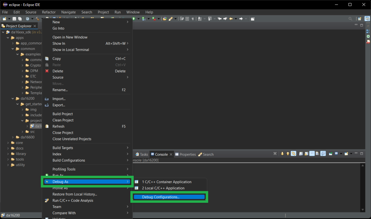
Open the GDB SEGGER J-Link Debugging entry in the list and select one of the three debugging
modes (reboot, attach, attach with RTOS info) and then select Debug.
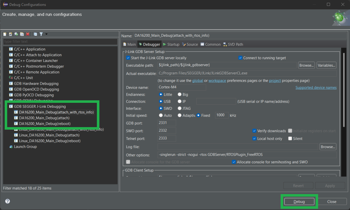
There are three debug methods supported by J-Link: "reboot", "attach" and "attach with RTOS info" which are defined as follows:
DA16x_Main_Debug (Reboot)/Linux_DA16x_Main_Debug(reboot)- In this mode, the debugger is executed after rebooting the image stored in SFLASH.
- In this mode, watchdog is turned off and wdt_kicking thread is not executed
DA16x_Main_Debug (Attach)/Linux_DA16x_Main_Debug(attach)- This mode executes the debugger in attach mode without rebooting the image currently stored in SFLASH.
Note: Before using
Attachmode, first turn off the watchdog using thesys.wdog offcommand as follows:[/DA16200] # sys.wdog off
- This mode executes the debugger in attach mode without rebooting the image currently stored in SFLASH.
DA16x_Main_Debug (attach_with_rtos_info)/Linux_DA16x_Main_Debug(attach_with_rtos_info)- Same as attach mode but displays thread information when in the debugger suspend state
Note: The current FreeRTOS SDK does not support automatic downloading of the firmware image into flash through the Eclipse debug interface. Therefore, the firmware must be loaded into SFLASH before starting to debug the application.
- Same as attach mode but displays thread information when in the debugger suspend state
OTA Update
There is a third option, however, it does require that the DA16200MOD module be preprogrammed to update its firmware over the air (OTA). Additionally, the firmware updates
Example: GPIO Control
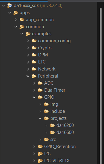
This example will demonstrate how to import and build one of the example projects from the DA16200 FreeRTOS SDK. This example will utilize the GPIO example project from the <sdk_root_directory>/apps/common/examples/Peripheral folder of the SDK (apps > common > examples > Peripheral > GPIO). The example project is written to read and toggle certain GPIO pins.
The
projects folder for the GPIO example, from the Peripheral examples folder of the DA16200 FreeRTOS SDK. (Click to enlarge)
By default, the example project will:
- Toggle the
GPIOA0andGPIOA4high and low. - Read the state of
GPIOA1. - The
GPIOA2andGPIOA3pins will be configured as interrupts:GPIOA2will be active low.GPIOA3will be active high.
Below are the prebuilt images for the GPIO example project, using version 3.2.4.0 of the SDK:
Build Project
Users with the DA16200 Thing Plus, can blink the STAT LED by modifying the following lines in the peripheral_sample_gpio.c file in the <sdk_root_directory>/apps/common/examples/Peripheral/GPIO/src folder:
- Replace
GPIO_PIN0withGPIO_PIN11on lines: 97, 162-163, 170, and 177 - Replace
GPIOA[0]withGPIOA[11]on line: 176
Users can also make the print outs in the serial debug interface easier to read by replacing low with low (add a extra space) to lines 177-179.
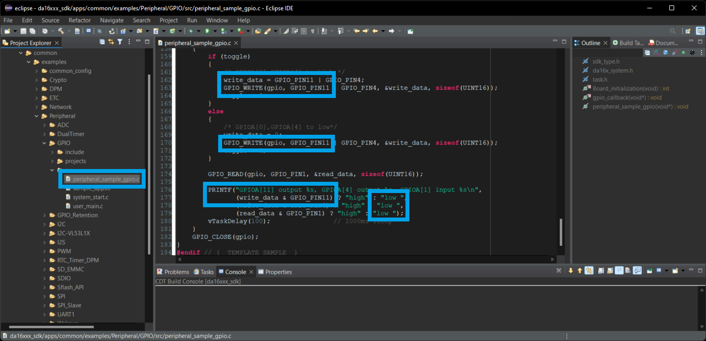
peripheral_sample_gpio.c file and most of the lines to modified in the Eclipde IDE. (Click to enlarge) Once the peripheral_sample_gpio.c file has been modified to suit the users needs, the example project can be imported and built in the Eclipse IDE. Users can then use the serial debug interface to upload the new firmware to the board. Once users reboot the DA16200MOD module, the new firmware should run automatically.
Users who have the DA16200 Thing Plus and have modified the code to toggle the STAT LED will see a blue LED blinking at about 1 second intervals.
Example: I2C
In the DA16200 FreeRTOS SDK, there is an I2C example project (apps > common > examples > Peripheral > I2C) that will write to and read from an EEPROM. This project is compatible with the Qwiic EEPROM. Below are the prebuilt images for the I2C example project, using version 3.2.4.0 of the SDK:
Build Project
After users have imported and built the project from the SDK, they can connect the Qwiic EEPROM and program their board. (No code modifications are necessary for this example project.)
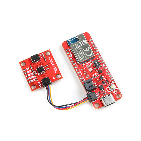
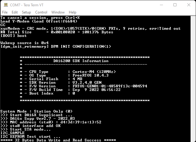
If connected properly, users should see a success message in the serial debug interface after the FRTOS image has been uploaded. The DA16200MOD will write 32 bytes to the EEPROM and then read the EEPROM to verify the data. The success message is displayed upon verification of the data.
Example: WiFi
STNP Sever
The Simple Network Time Protocol (SNTP) is as an Internet Protocol (IP) used to synchronize the clocks of networks of computers. In the DA16200 FreeRTOS SDK, there is an example project (apps > common > examples > ETC > Cur_Time) to access the Windows SNTP server and return the current time. Below are the prebuilt images for the Cur_Time example project, using version 3.2.4.0 of the SDK:
Once uploaded, if the WiFi connection has been provisioned, the board will print out the current time at regular intervals. At longer intervals, the current time will be updated from the Windows STNP server.
Build Project
To build the project, users should modify the following lines of code from the cur_time_sample.c file:
- Line 44:
TEST_SNTP_RENEW_PERIOD- Sets how often the board pulls the current time from SNTP server (seconds)
- Line 45:
TEST_TIME_ZONE- Sets the user/board's time zone (GMT)
- Example:
(-6 * 3600)represents GMT-6 or GMT (-6 hrs)
- Line 49:
CUR_TIME_LOOP_DELAY- Sets how often the current time is reported in the serial debug interface (seconds)
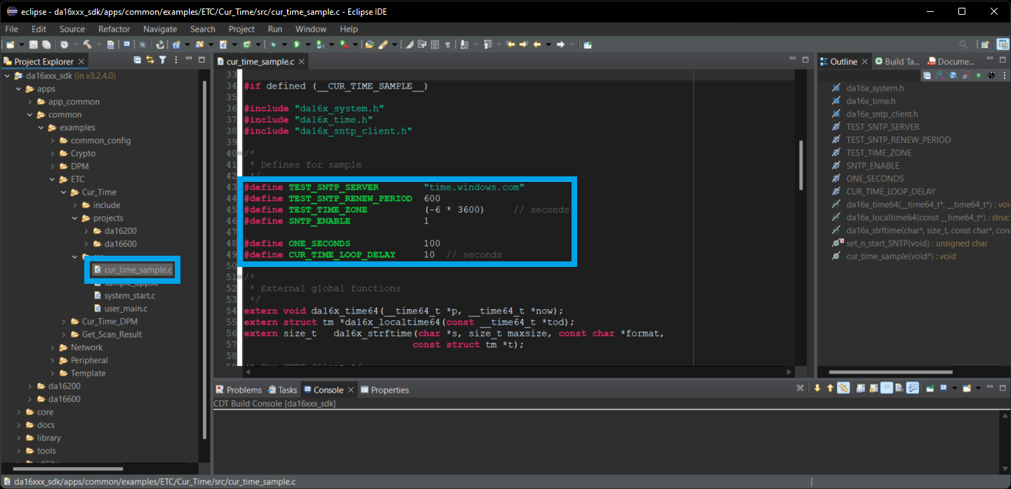
cur_time_sample.c file and the lines to modify in the Eclipde IDE. (Click to enlarge) Once the cur_time_sample.c file has been modified to suit the users needs, the example project can be imported and built in the Eclipse IDE. Users can then use the serial debug interface to upload the new firmware to the board. After users reboot the DA16200MOD module, the new firmware should run automatically. However, if the WiFi settings haven't been provisioned, users will need to configure the WiFi connection before the firmware starts outputting time stamps.

Cur_Time example after the WiFi has been provisioned. (Click to enlarge) OTA Firmware Update
The OTA (over the air) update example, allows users to update the firmware of the board by hosting the FRTOS image on a server. Through the WiFi connection, the board performs a simple HTTP request for the new firmware image. If the new image meets certain criteria, the board will download the firmware to a FRTOS slot in the SFlash memory and reboot that board to use that image.
Users can find the OTA update example project in the DA16200 FreeRTOS SDK (apps > common > examples > Network > OTA_Update). Below are the prebuilt images for the OTA_Update example project, using version 3.2.4.0 of the SDK:
Build Project
To build the project, users should modify the following lines of code from the ota_update_sample.c file:
- Modify line 52 to enable the OTA firmware update
#define SAMPLE_UPDATE_DA16_FW
- Modify line 60 with the address of the new firmware
static char ota_server_uri_rtos[256] = "https://sfecdn.s3.amazonaws.com/DA16200_FRTOS-GEN01-01-48589f13c-005000.img";
- Modify line 115 to reboot with the new firmware
g_ota_update_conf->auto_renew = 1;
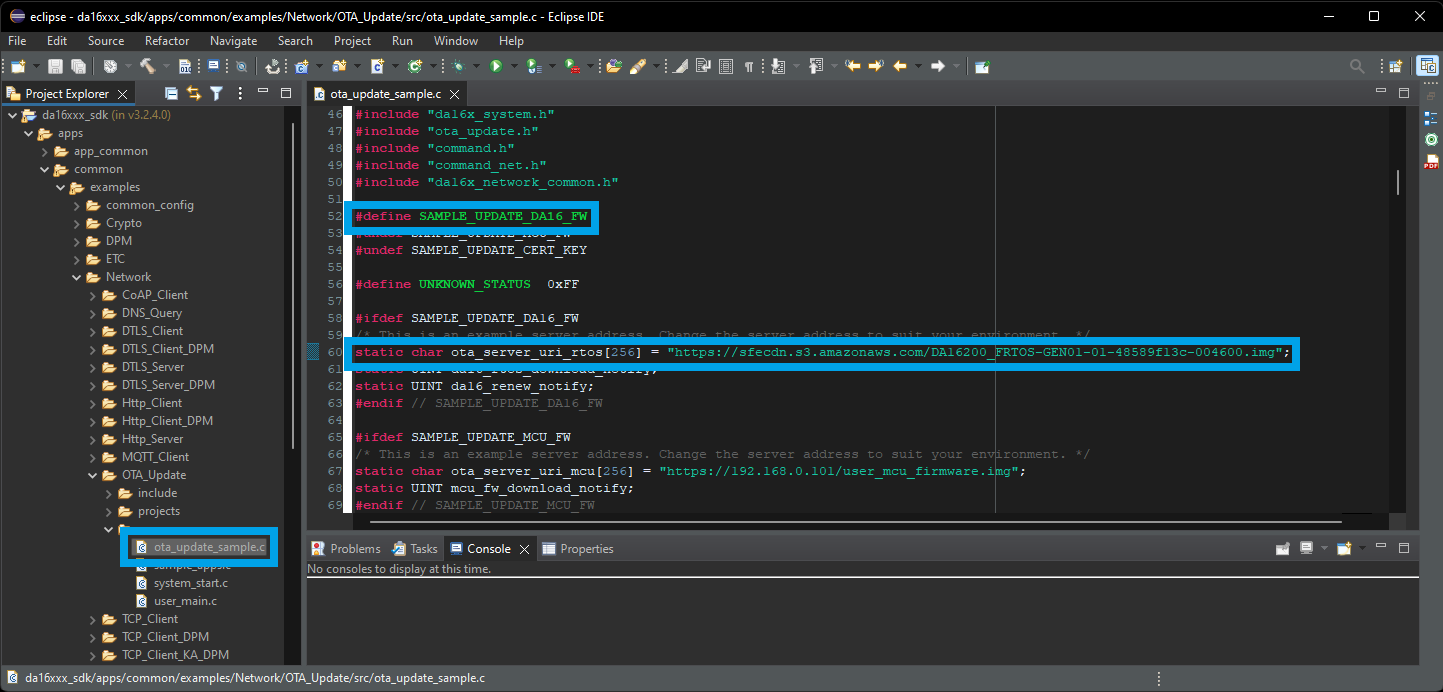
ota_update_sample.c file and the lines to modify in the Eclipde IDE. (Click to enlarge) Once the ota_update_sample.c file has been modified to suit the users needs, the example project can be imported and built in the Eclipse IDE. Users can then use the serial debug interface to upload the new firmware to the board. After users reboot the DA16200MOD module, the new firmware should run automatically. However, if the WiFi settings haven't been provisioned, users will need to configure the WiFi connection before the new firmware can be downloaded and updated. The new firmware that is uploaded to the S3 bucket, toggles the GPIO pins, including GPIOA11 for the status LED.
Troubleshooting Tips
We have also included some troubleshooting tips, below, for issues that users may come across.
- One of our employees compiled a great list of troubleshooting tips based on the most common customer issues. This is the perfect place to start.
- Users looking for support on general FreeRTOS questions, can click on this link. There users can get started with posting a topic in FreeRTOS forum.
- Users looking for support with the DA16200 SDK specifically, should post their topic on RenesasRulz forum.
MacOSX
Unfortunately, Renesas does not provide support for their SDK on MacOSX computers. Users will need to use a computer with a Windows or Linux operating system.
Serial Terminal Frozen
We have found that users could accidentally upload code, which may not function properly and potentially bog down the serial terminal; impeding it from taking inputs. If this occurs, users will need to use the J-Link programmer to program the module (with "known good" code) through the JTAG pins.
Reset
The reset button on this board doesn't cause the module to restart the firmware operation; it is used to reset the DA16200 module to the factory setting/configuration (when held down for +5 seconds). In order to reset the firmware, users can use the following commands in the serial debug interface:
reboot- This command will cause the module to restart the firmware execution.reset/bootreset- This command will take users to theMaskROMmode.boot- From theMaskROMcommand mode, this command will cause the module to restart the firmware execution.
Linux Driver
To get started with the DA16200MOD on RZ/G2L Linux systems using the DA16200/600's Linux driver source code, please refer to the Linux Driver Getting Started Guide
Issue with Project Builds
For users who are having issues importing or building a project for one of the application examples, they may need to delete and re-import the DA16200 SDK into the workspace.
In the Project Explorer tab of the Eclipse IDE,
WiFi Examples
To utilize example projects that are dependent on a WiFi connection, users will need to configure the WiFi settings:
- Provision the WiFi through the serial debug interface using the
setupcommand. - Provide the WiFi credentials in the
sample_preconfig.cfile of the SDK.
iPerf - Throughput Test
iPerf is an open-source, command-line network diagnostic tool. Users might be interested in this tool to perform a throughput test, which measures packet transfer performance. For more details on operating a throughput test, please refer to Section 6.3 of the Getting Started Guide:
OTA Update Example
With the OTA firmware update example, users may need to erase the firmware or swap which firmware image is currently running.
Erase the Firmware
When utilizing the OTA example, users may need to erase the firmware. This can be performed through the Net command mode.
- From the
[/DA16200] #prompt, enternetto enter the NET command mode. - From the
[/DA16200/NET] #prompt, enter theota_update infocommand to display the firmware information from the SFLASH memory - Users can then use the
ota_update erase_sflash <start> <size>command to erase a section of the 4MB SFLASH memory.- Example: To remove the firmware operating in the
RTOS #1section (0x1e2000) with 117268 bytes of memory, users will use the commandota_update erase_sflash 0x1e2000 117268
- Example: To remove the firmware operating in the
Boot Index
There are two slots, in which the main firmware image FRTOS can be stored in the SFLASH memory. These locations are at RTOS #0 (0x23000) and RTOS #1 (0x1e2000). Through the serial debug interface, users can specify which firmware image that the board boots up with.
- From the command console, the boot index can be changed using the
boot_idxcommandboot_idx 0- setsRTOS #0as the firmware to bootboot_idx 1- setsRTOS #1as the firmware to boot
- After running the
boot_idxcommand, run therebootcommand to boot the firmware that was selected.
Boot Failures
During the development process, there may be times when there is an error in the code or a problem downloading the firmware which could cause the DA16200/600 to fail to boot properly.
Please refer to Appendix D of the DA16200 FreeRTOS Getting Started Guide.
Prebuilt Images
In case users lock-up or break the firmware on their board, they can upload these prebuilt images for the DA16200 FreeRTOS SDK (version 3.2.4.0). If the board is locked up, the only way to recover the board is flash the firmware with a J-Link debug probe. Click on the buttons below to download the prebuilt images:
Resources and Going Further
For more on the FreeRTOS and the DA16200 module, check out the links below:
- FreeRTOS
- Dialog DA16200MOD Product Page
- Documentation for the DA16200
- DA16200MOD Datasheet (v3.1)
- DA16200 FreeRTOS SDK
- Getting Started Guide (v1.2)
- Programming Guide (v1.5)
- OTA Update Manual (v1.2)
- Application Manual for SDK Examples
- Software and Tools for the DA16200
- DA16200 FreeRTOS SDK (v3.2.4.0)
- DA16200 FreeRTOS SDK Image (v3.2.4.0)
- Support for the DA16200
- Documentation for the DA16200