Getting Started with the DA16200 FreeRTOS SDK
Programming and Debugging
There are two primary methods to update the main firmware (FRTOS) image, with Y-Modem through the serial debug interface or with a J-Link programmer (debugging probe).
Serial Terminal (Y-Modem)
Before proceeding further, users will need to update the firmware for the DA16200MOD.
- There are two firmware images for the DA16200 FreeRTOS SDK:
- FBOOT is the bootloader image which is used to initialize the DA16200 and launch the main firmware.
- File Name:
DA16200_FBOOT-GEN01-01-XXXXXXXXX_W25Q32JW.img - The bootloader image must be the first thing loaded into flash for a new device.
- Since the bootloader image contains SFDP (flash specific) information, the bootloader must be loaded into flash before other images are loaded.
- When the SDK is updated, always load the bootloader image first.
- File Name:
- FRTOS is the main firmware image which includes the RTOS and user applications.
- File Name:
DA16200_FRTOS-GEN01-01-XXXXXXXXX-XXXXXX.img
- File Name:
- FBOOT is the bootloader image which is used to initialize the DA16200 and launch the main firmware.
- The DA16200 SDK can be used to build the firmware images for a specific example project from the DA16200 FreeRTOS SDK.
To update the firmware on the DA16200MOD, users will need to connect to the module to a computer through the serial debug interface. From a serial terminal, users will need to use Y-Modem to upload the updated SDK bootloader and firmware images to the DA16200MOD.
Upload New Project Firmware
The process for uploading new firmware for an SDK project build is a similar method to updating the SDK firmware. Users will need to connect to the module to a computer through the serial debug interface. From a serial terminal, users will use Y-Modem to upload the new firmware image to the DA16200MOD.
- To update the firmware images on the DA16200:
- In the serial terminal, at the
[/DA16xxx]prompt, enterresetto access to the MaskROM mode.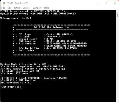 Splash screen and intial prompt for the serial debug interface. (Click to enlarge)
 - At the
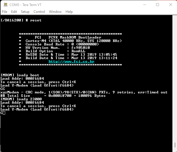
[MROM]prompt, use theloadycommand to upload one of the firmware images.- For the main firmware image (
FRTOS), use theloady 23000command forRTOS #0. - When uploading a main firmware image (
FRTOS) for a project built with the SDK (no version update), it isn't necessary to upload the second bootloader firmware image (FBOOT). Command mode to upload the
FRTOSimage. (Click to enlarge)
- For the main firmware image (
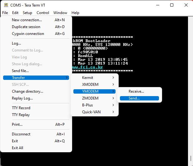
- In the terminal emulation program, start the Y-Modem file transfer:
- For Windows Tera Term:
- From the File menu, select Transfer > YMODEM > Send.
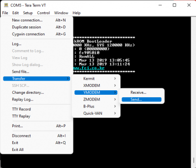 Y-Modem file transfer. (Click to enlarge)
 - Navigate to where the firmware image is stored, choose the required firmware image and start the download.
- From the File menu, select Transfer > YMODEM > Send.
- For Linux
minicom:- Press Ctrl+A+S and select
ymodemfrom the menu. - Navigate to where the firmware image is stored, choose the required firmware image and start the download.
- Press Ctrl+A+S and select
- For Windows Tera Term:
- After the transfer completes, the total size is displayed. Use the
bootcommand at the[MROM]prompt to restart the firmware.
- In the serial terminal, at the

J-Link Software
Hardware Note: In order to program and debug the DA16200MOD, a J-Link Lite (or higher) programmer (i.e. debug probe) is required. Users may need to solder on a JTAG header to connect a J-Link programmer to their board; an adapter may also be required.
Below are a few examples of J-Link programmers and JTAG accessories from our catalog:
J-Link EDU Mini Programmer
PGM-15345
J-Link BASE Compact Programmer
PGM-15347
JTAG 20 Pin 0.1 In. To 10 Pin 0.05 In. Adapter
PGM-18421For a comparison of the different J-Link programmer models, please refer to the Segger website.
Software Note: Below are the minimum requirements to setup the J-Link programmer to be used in the Eclipse IDE for the DA16200 FreeRTOS SDK:
-
Eclipse 2021-06 (4.20.0) or later
Download the latest version of the Eclipse IDE -
J-Link software V6.98 or later
Download the latest version of J-Link
Program
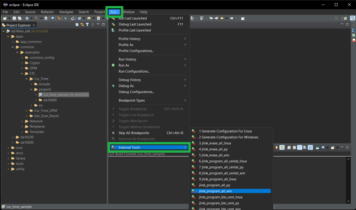
To program binaries into a target device, users will need to execute the program_all_jtag_win script for Windows or the program_all_jtag_linux script for Linux in the External Tools menu.
- Select the project to be programmed in the Project Explorer.
- Under the
Runmenu, selectExternal Tools(i.e. Run > External Tools). - Select
program_all_jtag_winorprogram_all_jtag_linux.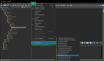 Select script to program with J-Link. (Click to enlarge)
The following scripts are available in the DA16200 FreeRTOS SDK:
- Erase all contents of the flash memory:
erase_all_jtag_winerase_all_jtag_linux
- Program all images into the flash memory:
program_all_jtag_winprogram_all_jtag_linux
- Program FBOOT image into the flash memory:
program_boot_jtag_winprogram_boot_jtag_linux
- Program FRTOS image into the flash memory:
program_rtos_jtag_winprogram_rtos_jtag_linux
Debug
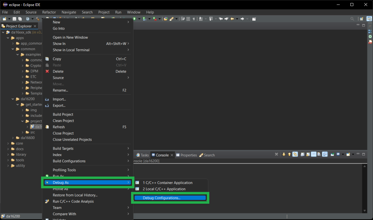
To start debugging an application, right-click on the project in the Project Explorer and select Debug As > Debug Configurations.
Open the GDB SEGGER J-Link Debugging entry in the list and select one of the three debugging
modes (reboot, attach, attach with RTOS info) and then select Debug.
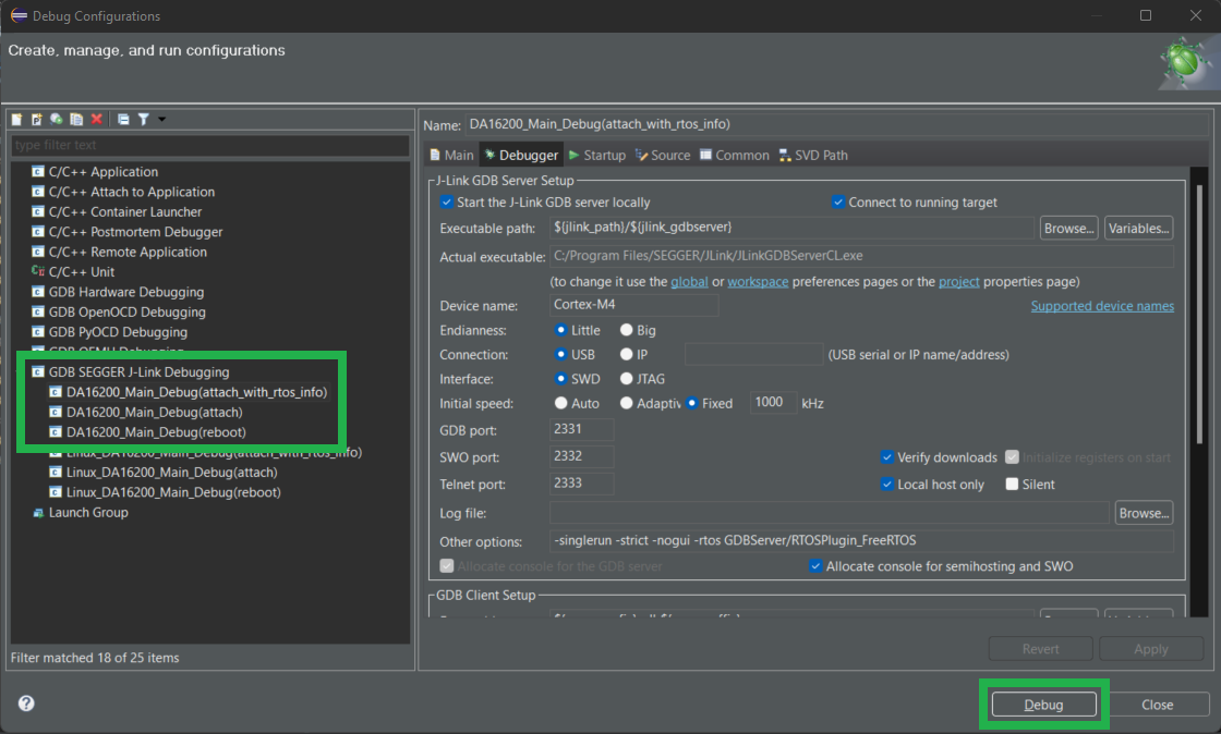
There are three debug methods supported by J-Link: "reboot", "attach" and "attach with RTOS info" which are defined as follows:
DA16x_Main_Debug (Reboot)/Linux_DA16x_Main_Debug(reboot)- In this mode, the debugger is executed after rebooting the image stored in SFLASH.
- In this mode, watchdog is turned off and wdt_kicking thread is not executed
DA16x_Main_Debug (Attach)/Linux_DA16x_Main_Debug(attach)- This mode executes the debugger in attach mode without rebooting the image currently stored in SFLASH.
Note: Before using
Attachmode, first turn off the watchdog using thesys.wdog offcommand as follows:[/DA16200] # sys.wdog off
- This mode executes the debugger in attach mode without rebooting the image currently stored in SFLASH.
DA16x_Main_Debug (attach_with_rtos_info)/Linux_DA16x_Main_Debug(attach_with_rtos_info)- Same as attach mode but displays thread information when in the debugger suspend state
Note: The current FreeRTOS SDK does not support automatic downloading of the firmware image into flash through the Eclipse debug interface. Therefore, the firmware must be loaded into SFLASH before starting to debug the application.
- Same as attach mode but displays thread information when in the debugger suspend state
OTA Update
There is a third option, however, it does require that the DA16200MOD module be preprogrammed to update its firmware over the air (OTA). Additionally, the firmware updates