Getting Started with the DA16200 FreeRTOS SDK
Example: WiFi
STNP Sever
The Simple Network Time Protocol (SNTP) is as an Internet Protocol (IP) used to synchronize the clocks of networks of computers. In the DA16200 FreeRTOS SDK, there is an example project (apps > common > examples > ETC > Cur_Time) to access the Windows SNTP server and return the current time. Below are the prebuilt images for the Cur_Time example project, using version 3.2.4.0 of the SDK:
Once uploaded, if the WiFi connection has been provisioned, the board will print out the current time at regular intervals. At longer intervals, the current time will be updated from the Windows STNP server.
Build Project
To build the project, users should modify the following lines of code from the cur_time_sample.c file:
- Line 44:
TEST_SNTP_RENEW_PERIOD- Sets how often the board pulls the current time from SNTP server (seconds)
- Line 45:
TEST_TIME_ZONE- Sets the user/board's time zone (GMT)
- Example:
(-6 * 3600)represents GMT-6 or GMT (-6 hrs)
- Line 49:
CUR_TIME_LOOP_DELAY- Sets how often the current time is reported in the serial debug interface (seconds)
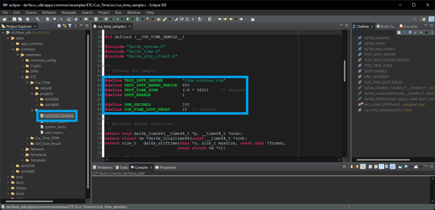
cur_time_sample.c file and the lines to modify in the Eclipde IDE. (Click to enlarge) Once the cur_time_sample.c file has been modified to suit the users needs, the example project can be imported and built in the Eclipse IDE. Users can then use the serial debug interface to upload the new firmware to the board. After users reboot the DA16200MOD module, the new firmware should run automatically. However, if the WiFi settings haven't been provisioned, users will need to configure the WiFi connection before the firmware starts outputting time stamps.

Cur_Time example after the WiFi has been provisioned. (Click to enlarge) OTA Firmware Update
The OTA (over the air) update example, allows users to update the firmware of the board by hosting the FRTOS image on a server. Through the WiFi connection, the board performs a simple HTTP request for the new firmware image. If the new image meets certain criteria, the board will download the firmware to a FRTOS slot in the SFlash memory and reboot that board to use that image.
Users can find the OTA update example project in the DA16200 FreeRTOS SDK (apps > common > examples > Network > OTA_Update). Below are the prebuilt images for the OTA_Update example project, using version 3.2.4.0 of the SDK:
Build Project
To build the project, users should modify the following lines of code from the ota_update_sample.c file:
- Modify line 52 to enable the OTA firmware update
#define SAMPLE_UPDATE_DA16_FW
- Modify line 60 with the address of the new firmware
static char ota_server_uri_rtos[256] = "https://sfecdn.s3.amazonaws.com/DA16200_FRTOS-GEN01-01-48589f13c-005000.img";
- Modify line 115 to reboot with the new firmware
g_ota_update_conf->auto_renew = 1;
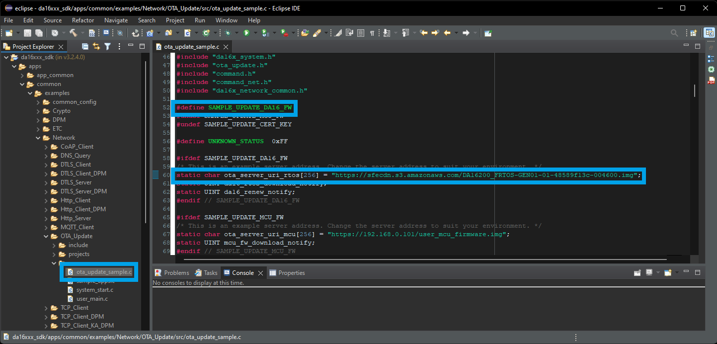
ota_update_sample.c file and the lines to modify in the Eclipde IDE. (Click to enlarge) Once the ota_update_sample.c file has been modified to suit the users needs, the example project can be imported and built in the Eclipse IDE. Users can then use the serial debug interface to upload the new firmware to the board. After users reboot the DA16200MOD module, the new firmware should run automatically. However, if the WiFi settings haven't been provisioned, users will need to configure the WiFi connection before the new firmware can be downloaded and updated. The new firmware that is uploaded to the S3 bucket, toggles the GPIO pins, including GPIOA11 for the status LED.