Fingerprint Scanner (GT-521Fxx) Hookup Guide
 bboyho
Troubleshooting
Listed below are frequently asked questions and tech support tips on troubleshooting common issues related to the fingerprint scanner.
1.) I am not sure if the fingerprint scanner is responding to any of the commands with my Arduino. What can I do?
Make sure that there are no loose connections. If you are using the JST SH jumper 4 wire assembly, the cable's wire is relatively thin compared to the Arduino's socket. A small bump can break the connection requiring you to power cycle the fingerprint scanner or reset the Arduino.
Also, make sure that you are connecting the fingerprint scanner to your microcontroller correctly based on the Arduino model and defined software serial pins.
2.) Scanner not recognizing your fingers when enrolling?
There can be issues trying to enroll when using the SDK_Demo.exe or Arduino example code. This is usually due to fingers being dry and not having good contact on the scanner. The finger has to have the same pressure applied and be placed in the same position for all three enrollments. The timing of your finger on the scanner is a little tricky too. A tech support representative had to try a few times before it was able to enroll a finger. This is common with any fingerprint scanner like the one that is on a smartphone.
If you see these errors, you probably did not place your finger on the fingerprint scanner sufficiently for each enrollment:
Bad finger!
or
Failed to capture second finger
or
The enrollment is failed!
If you are using an FTDI, try to follow the directions for enrolling with a FTDI again. You may need to close out the program and unplugging/replugging the FTDI before re-enrolling. If you are using an Arduino, try the enrollment process again by placing your finger on the scanner, resetting the Arduino, and following the directions in the serial monitor.
3.) Scanner not recognizing your fingers when verifying?
If you are trying to verify a fingerprint, make sure to place the finger on the scanner just like when it was enrolled. The same conditions for scanning a fingerprint apply as explained above for enrolling.
4.) Will the GT-521F32 / GT-521F52 fingerprint scanner work with the FPS_GT511C3 library?
Yes, it will. It has been tested. Each of the fingerprint scanners use the same command protocols so the Arduino example code can be used for any of the scanners. However, the library will not be compatible if you using a different scanner that is not manufactured by ADH-Tech.
5.) Can I use an Arduino Due?
Unfortunately, the fingerprint scanner's Arduino example code for the does not work with the Arduino Due. You would need to modify the code and use it with the hardware serial UARTs because the Arduino Due does not support software serial. This old forum post will explain why there are compilation errors with the example code using the Arduino Due board definition => Arduino.cc Forums: SoftwareSerial for Arduino Due.
6.) What are the dimensions of the fingerprint scanner?
The dimensions are listed on page 8 of the datasheet.
7.) I soldered to the back of the fingerprint scanner and none of the Arduino examples work.
Those pins are broken out if you wanted to connect the fingerprint scanner directly to a USB port. The USB data lines are different from a serial UART protocol. If you are using the Arduino examples for your project, it is recommended to connect to the JST SH connector. If you are interested in plugging the scanner directly to your computer's COM port, feel free to test it out and experiment. It has been tested to work with the previous models.
Fingerprint Scanner USB Pinout
Surprise! You found the extra section on how to connect to the USB pins! The connection to the USB was not included in the beginning of the tutorial because the main objective was to use it in an embedded project with an Arduino microcontroller. To connect the fingerprint scanner with the demo software and your computer's USB port, you can connect the pads on the back of the board labeled J1 directly to the USB port of your computer. The image and table below shows the pinout:
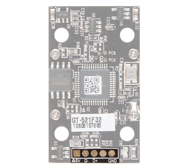
| Fingerprint Scanner | USB Port |
|---|---|
| Shield (right most pin) | USB Shield (not necessary if using a USB breakout board). Tied to GND. |
| GND | GND (Standard USB Black Wire) |
| D+ | D+ (Standard USB White Wire) |
| D- | D- (Standard USB Green Wire) |
| Vcc (square pad) | 5V (Standard USB Red Wire) |
For more information about soldering to the USB pads, check out the instructions provided in the the older tutorial. The directions are essentially the same.