Fingerprint Scanner (GT-521Fxx) Hookup Guide
 bboyho
Hardware Hookup
The fingerprint scanner requires a serial UART connection and power. There are a few options to connect to the sensor depending on what UART device you are using. The easiest would be to use an FTDI but you can also use any microcontroller that has a UART.
1.) Connecting w/ a 3.3V FTDI
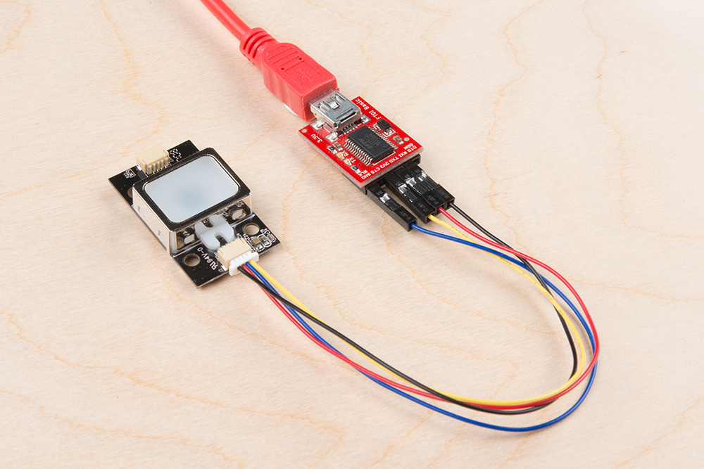
Option 1: Qwiic Cable
To connect the fingerprint scanner to your computer, it is recommended to connect the JST SH cable to a USB-to-serial converter. Here are the minimum required parts you would need to get started:
- Fingerprint Scanner (GT-521F32 or GT-521F52)
- Qwiic Cable - Breadboard Compatible
- 3.3V FTDI Basic Breakout
- Mini-B USB Cable
Below are the following connections you would need to make with the JST-SH connector labeled as J2:
| Fingerprint Scanner [Pin #] | FTDI 3.3V |
|---|---|
| UART_TX (3.3V TTL) [Pin 1] | RX |
| UART_RX (3.3V TTL) [Pin 2] | TX |
| GND [Pin 3] | GND |
| Vin (3.3V~6V) [Pin 4] | 3.3V |
After connecting, the setup should look like the image below.
Option 2: Making a Custom Adapter
If you are using the JST SH Jumper 4 Wire Assembly instead of the Qwiic cable, it is highly recommended that you make a custom adapter by soldering to the ends of the wire for a secure connection. This will ensure that the connection is not loose when inserting it into female header sockets of an FTDI or the RedBoard/Arduino Uno. The cable wire is small compared to the female header socket. A small bump can mess with the serial UART or power between the fingerprint scanner and converter. This may require you to reconnect the scanner to your computer or device. Making an adapter will also provide quick access to the small 4-pin JST-SH connector that is on the scanner.
For more information on how to make a custom adapter, please refer to the older tutorial. Remember, the pin locations are the same so the adapter can work with the current fingerprint scanner.
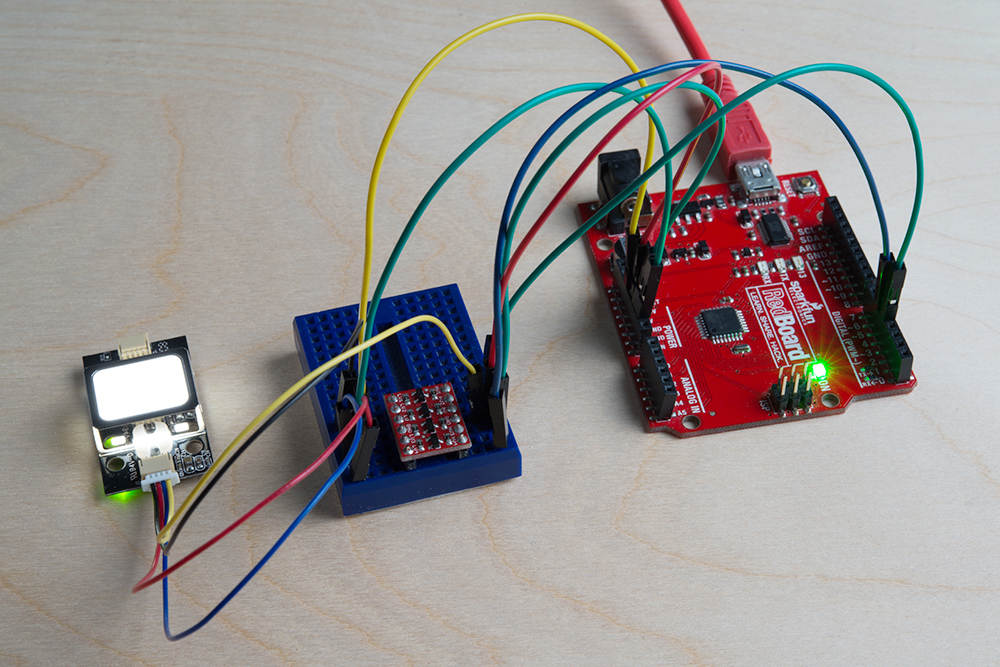
2.) Connecting w/ a 5V Arduino
Before using the Arduino's example code, make sure that the logic levels match. If you are using a 5V Arduino, you could use a dedicated logic level converter or resistors for voltage division. Here are the minimum parts you would need to get started:
- Fingerprint Scanner (GT-521F32 or GT-521F52)
- Qwiic Cable
- Redboard or Arduino Uno
- Mini-Breadboard
- Bi-Directional Logic Level Converter or 3x 10kOhm Resistors
- M/M Jumper Wires
Option 1: Dedicated Bi-Directional Logic Level Converter (LLC)
It is recommended to use a dedicated bi-directional LLC for a reliable connection if you are using a 5V Arduino microcontroller. Assuming that you have soldered the header pins to the logic level converter, you would need to make these connections:
| Fingerprint Scanner (Pin #) | Logic Level Converter (Low Side) | Logic Level Converter (High Side) | 5V Arduino w/ Atmega328P |
|---|---|---|---|
| UART_TX (3.3V TTL) (Pin 1) | LV1 | HV1 | RX (pin 4) |
| UART_RX (3.3V TTL) (Pin 2) | LV4 | HV4 | TX (pin 5) |
| GND (Pin 3) | GND | GND | GND |
| LV | 3.3V | ||
| Vin (3.3V~6V) (Pin 4) | HV | 5V |
After wiring the circuit, it should look like this:
Option 2: Voltage Division w/ 3x 10kOhm Resistors
Otherwise, you could use 3x 10kOhm resistors to divide the voltage from a 5V Arduino down to 3.3V for the fingerprint scanner (FPS) similar to the "Uni-Directional" application circuit on our old logic level converter as shown below:

Below is the connection between the FPS, 5V Arduino, and resistors for voltage division:
| Voltage Divider | Fingerprint Scanner(Pin #) | Voltage Divider | 5V Arduino w/ Atmega328P |
|---|---|---|---|
| UART_TX (3.3V TTL) (Pin 1) | RX (pin 4) | ||
| GND < 10kOhm > 10kOhm |
UART_RX (3.3V TTL) (Pin 2) | 10kOhm | TX (pin 5) |
| GND | GND (Pin 3) | GND | GND |
| Vin (3.3V~6V) (Pin 4) | 5V |
Note: You can add the two 10kOhm resistors in series for 20kOhms.
After wiring the circuit up, it should look like this:
