ESP32 Thing Motion Shield Hookup Guide
 MTaylor
 Introduction
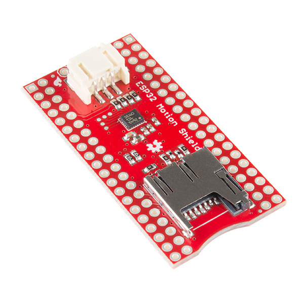
The ESP32 Thing Motion Shield is a versatile addition to our ESP32 Thing. Small movements can be detected with the tried and true LSM9DS1 IMU, large movements and time can be detected with the addition of a GPS sensor. There's a port for the GP-20U7 module, and breakout pins for any serial device. Data can be easily logged by adding a microSD card to the slot. And did I mention there's a general purpose LED? It works quite well to display GPS lock state!
SparkFun ESP32 Thing Motion Shield
DEV-14430Required Materials
To fully follow this hookup guide, you would will need the following materials. You may not need everything though, depending on what you have and what you want to do. Add it to your cart, read through the guide, and adjust the cart as necessary depending on what you would like.
Recommended Tools
You will need a soldering iron, solder, and general soldering accessories.


Suggested Reading
If you aren't familiar with the following concepts, we recommend checking out these tutorials before continuing.
Assembly:
How to Solder: Through-Hole Soldering
Working with Wire
Concepts:
GPS Basics
Gyroscope
Accelerometer Basics
Programming:
Installing Arduino IDE
Hexadecimal
ESP32 Thing Hookup Guide
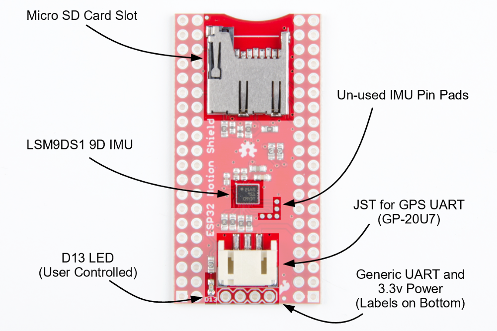
Hardware Overview
The hardware is a conglomeration of an SD card socket, LSM9DS1 IMU, and GPS serial port. There's also an LED for general indication.
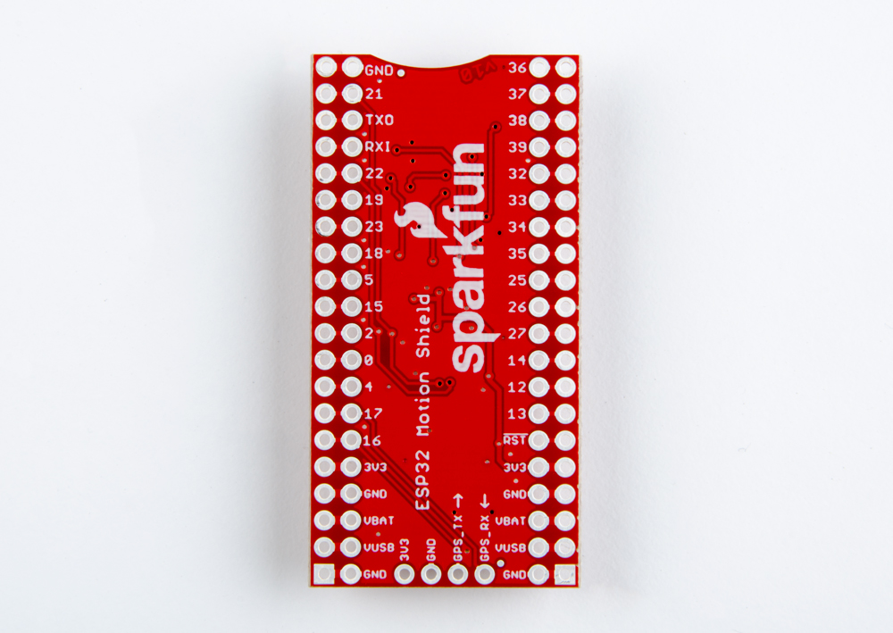
The signals that are used are show here, grouped by function.
| ESP32 Thing Pin | Direction | Signal | Group | ESP32 Function |
|---|---|---|---|---|
| GPIO 13 | I | LED | LED | GPIO 13 |
| GPIO 16 | I | GPS_TX | GPS UART | Serial 1 |
| GPIO 17 | O | GPS_RX | GPS UART | Serial 1 |
| GPIO 18 | I | SD_SCK | SD Card | SPI SCK |
| GPIO 19 | O | SD_DO | SD Card | SPI MISO |
| GPIO 23 | I | SD_DI | SD Card | SPI MOSI |
| GPIO 33 | I |
SD_CS | SD Card | GPIO 33 |
| GPIO 38 | I |
SD_CD | SD Card | GPIO 38 |
| GPIO 21 | I/O | SDA | IMU | I2C SDA |
| GPIO 22 | I | SCL | IMU | I2C SCL |
Hardware Assembly
In this section, we'll prepare the shield for a development environment by adding headers. This section also shows what the GPS module, battery, and SD card look like when properly inserted.

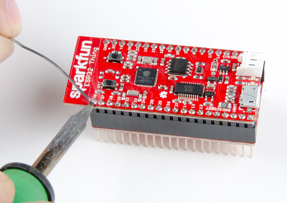
Attach the Stackable Headers to the Motion Shield
Solder a single pin on each header. Make sure the headers are straight, and lined up. You can use perf board, or an already populated ESP32 Thing to help with alignment.
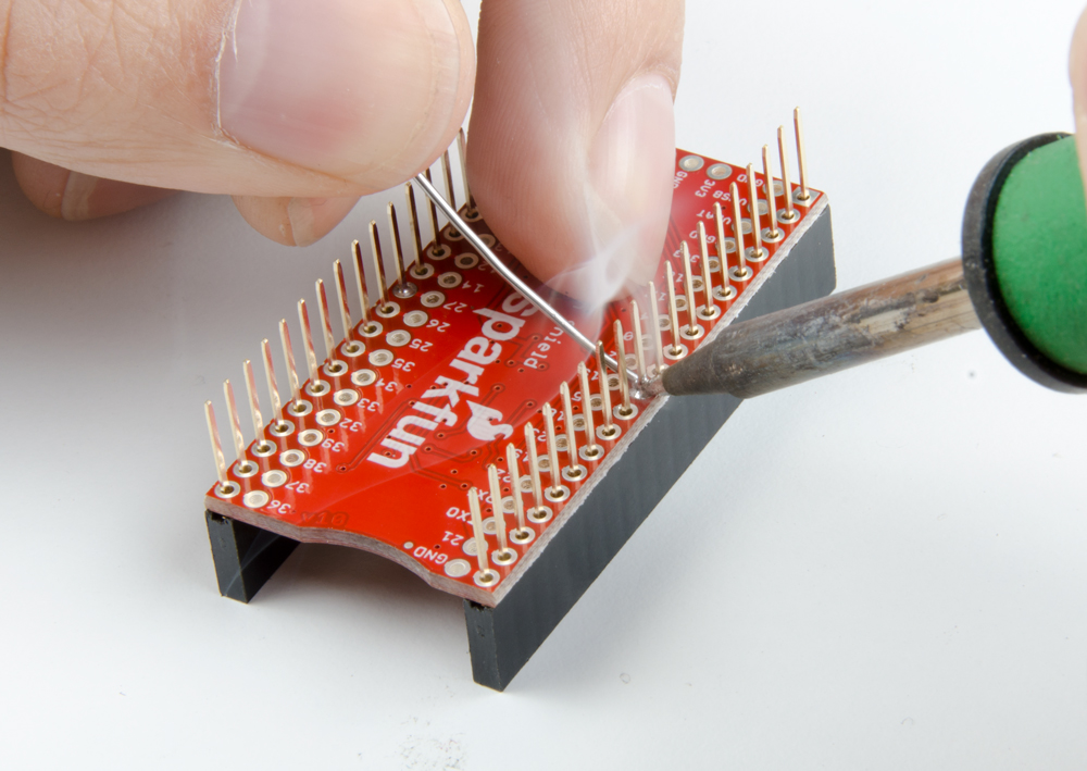
Solder the rest of the pins focusing on getting nice, even, conic fillets.

Attach the Headers to the ESP32 Thing
Put the pin headers in the shield, and set the ESP32 Thing on top. Then, apply solder and build up nice fillets making sure to not bridge any pins.
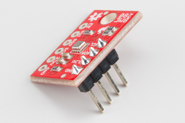
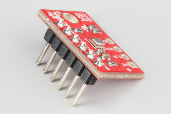
Adding an Optional Sensor
If you're using a BME280 to try out the I2C or SPI port, install headers on it as well. See the BME280 Hookup Guide for more information.
 |
 |
 |
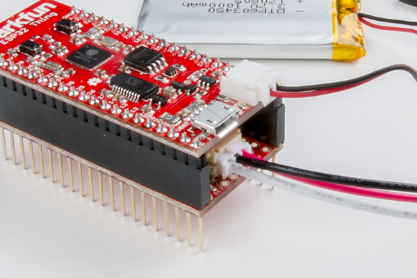
3-Pin JST and microSD Card
Make sure the JST and microSD cards are installed properly.
If the JST connectors feel like they're not going in, don't force them, try wiggling them instead. They will hang out a bit when properly seated.
The microSD card slot is dual position with click feature, and the PCB has a recess. The card should easily click in and out.
 |
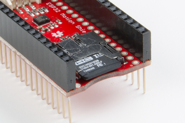 |
The JST connectors are seated properly, protruding slightly from their sockets (left). When the SD card is inserted properly (right), it should be flush with the edge of the board.
Stack and Connect Additional Parts!
Stack the ESP32 Thing on the ESP32 Thing Motion Shield.
You can also install the stack in a breadboard, letting the antenna hang off the end so you have the most room left to work with when prototyping. If using the BME280, install that on the breadboard as well and wire the sensor as explained in the "Using the I2C and SPI Buses" example.
Software
General Requirements
Note: This example assumes you are using the latest version of the Arduino IDE on your desktop. If this is your first time using Arduino, please review our tutorial on installing the Arduino IDE. If you have not previously installed an Arduino library, please check out our installation guide.
The Motion Shield itself doesn't use any special software. It relies on the SD card library from the ESP32 core, and the LSM9DS1 library, plus whatever you attach to it. Make sure you've got the following installed before continuing on to the examples.
- ESP32 Thing Arduino Core -- Follow the instructions from the ESP32 Thing Hookup Guide.
- Arduino Libraries:
- LSM9DS1 -- Follow the LSM9DS1 Hookup Guide or use the library manager.
- BME280 -- Follow the BME280 Hookup Guide or use the library manager.
- Your choice of NMEA parser, or do it yourself! -- Examples are contained and need no libraries.
The example code used throughout this tutorial can also be found in the ESP32 Thing Motion Shield's GitHub repository.
General Tips
Strapping Pins
The following pins are used to configure the CPU at power up to indicate various booting methods (known as 'strapping' pins). These are exposed to the user, but should be avoided for beginners. Attaching a device that matches the default state during power up should not interfere with the boot procedure. If it seems like the ESP32 isn't booting properly, investigate these pins.
| ESP32 Pin Name | ESP32 Thing Pin Name | Default Pull | Description |
|---|---|---|---|
| MTDI | GPIO12 | High | Internal LDO voltage select |
| GPIO0 | GPIO0 | High | SPI/Download boot |
| GPIO2 | GPIO2 | Low | SPI/Download boot |
| MTDO | GPIO15 | High | U0TXD toggling mode/timing |
| GPIO5 | GPIO5 | High | U0TXD timing |
| GPIO4 | GPIO4 | Low | Unknown |
If U0TXD, GPIO2, GPIO5 are floating, GPIO0 determines boot mode.
See the ESP32 Datasheet for more information.
Input-only Pins
GPIO34 through GPIO39 work only as inputs, with no internal pull capabilities (as of 10/31/2017).
Standard pin naming
The pins listed in Hardware Overview are also listed here as #defines you can use. Not all are necessary for every application, but it's nice to have them all in one place for reference.
language:c
#define AUX_LED_PIN 13
#define GPS_TX_PIN 16
#define GPS_RX_PIN 17
#define SD_SCK_PIN 18
#define SD_DO_PIN 19
#define SD_DI_PIN 23
#define SD_CS_PIN 33
#define SD_CD_PIN 38
#define IMU_SDA_PIN 21
#define IMU_SCL_PIN 22
Using the IMU
The IMU on the shield is the LSM9DS1, which is connected the the ESP32 Thing to the I2C port only. Any of the examples from the LSM9DS1 library should be good to go, as long as you specify the port type to be I2C with default addresses.
There are two examples in this section that will work without modification on the Motion Board.
The first example is a modification of the LSM9DS1_ESP32_Settings.ino example, with SPI related information removed. This is a good place to start because it shows all of the API, and you can comment out what you don't need.
language:c
/*****************************************************************
LSM9DS1_ESP32_Settings.ino
SFE_LSM9DS1 Library Settings Configuration Example
Original Creation: August 13, 2015 by Jim Lindblom
https://github.com/sparkfun/LSM9DS1_Breakout

This Arduino sketch demonstrates how to configure every
possible configuration value in the SparkFunLSM9DS1 library.

It demonstrates how to set the output data rates and scales
for each sensor, along with other settings like LPF cutoff
frequencies and low-power settings.

It also demonstrates how to turn various sensors in the
LSM9DS1 on or off.

Hardware setup: This library is intended to be used with a
ESP32 Motion shield connected directly to the ESP32 Thing.

Development environment specifics:
IDE: Arduino 1.8.2
Hardware Platform: ESP32 Arduion Board

This code is beerware. If you see me (or any other SparkFun
employee) at the local, and you've found our code helpful,
please buy us a round!

Distributed as-is; no warranty is given.
*****************************************************************/
// Include SparkFunLSM9DS1 library and its dependencies
#include <Wire.h>
#include <SPI.h>
#include <SparkFunLSM9DS1.h>

LSM9DS1 imu;  // Create an LSM9DS1 object

// Mag address must be 0x1E, would be 0x1C if SDO_M is LOW
#define LSM9DS1_M   0x1E
// Accel/gyro address must be 0x6B, would be 0x6A if SDO_AG is LOW
#define LSM9DS1_AG  0x6B

// Global variables to keep track of update rates
unsigned long startTime;
unsigned int accelReadCounter = 0;
unsigned int gyroReadCounter = 0;
unsigned int magReadCounter = 0;
unsigned int tempReadCounter = 0;

// Global variables to print to serial monitor at a steady rate
unsigned long lastPrint = 0;
const unsigned int PRINT_RATE = 500;


void setupGyro()
{
// [enabled] turns the gyro on or off.
imu.settings.gyro.enabled = true;  // Enable the gyro
// [scale] sets the full-scale range of the gyroscope.
// scale can be set to either 245, 500, or 2000
imu.settings.gyro.scale = 245; // Set scale to +/-245dps
// [sampleRate] sets the output data rate (ODR) of the gyro
// sampleRate can be set between 1-6
// 1 = 14.9    4 = 238
// 2 = 59.5    5 = 476
// 3 = 119     6 = 952
imu.settings.gyro.sampleRate = 3; // 59.5Hz ODR
// [bandwidth] can set the cutoff frequency of the gyro.
// Allowed values: 0-3. Actual value of cutoff frequency
// depends on the sample rate. (Datasheet section 7.12)
imu.settings.gyro.bandwidth = 0;
// [lowPowerEnable] turns low-power mode on or off.
imu.settings.gyro.lowPowerEnable = false; // LP mode off
// [HPFEnable] enables or disables the high-pass filter
imu.settings.gyro.HPFEnable = true; // HPF disabled
// [HPFCutoff] sets the HPF cutoff frequency (if enabled)
// Allowable values are 0-9. Value depends on ODR.
// (Datasheet section 7.14)
imu.settings.gyro.HPFCutoff = 1; // HPF cutoff = 4Hz
// [flipX], [flipY], and [flipZ] are booleans that can
// automatically switch the positive/negative orientation
// of the three gyro axes.
imu.settings.gyro.flipX = false; // Don't flip X
imu.settings.gyro.flipY = false; // Don't flip Y
imu.settings.gyro.flipZ = false; // Don't flip Z
}

void setupAccel()
{
// [enabled] turns the acclerometer on or off.
imu.settings.accel.enabled = true; // Enable accelerometer
// [enableX], [enableY], and [enableZ] can turn on or off
// select axes of the acclerometer.
imu.settings.accel.enableX = true; // Enable X
imu.settings.accel.enableY = true; // Enable Y
imu.settings.accel.enableZ = true; // Enable Z
// [scale] sets the full-scale range of the accelerometer.
// accel scale can be 2, 4, 8, or 16
imu.settings.accel.scale = 8; // Set accel scale to +/-8g.
// [sampleRate] sets the output data rate (ODR) of the
// accelerometer. ONLY APPLICABLE WHEN THE GYROSCOPE IS
// DISABLED! Otherwise accel sample rate = gyro sample rate.
// accel sample rate can be 1-6
// 1 = 10 Hz    4 = 238 Hz
// 2 = 50 Hz    5 = 476 Hz
// 3 = 119 Hz   6 = 952 Hz
imu.settings.accel.sampleRate = 1; // Set accel to 10Hz.
// [bandwidth] sets the anti-aliasing filter bandwidth.
// Accel cutoff freqeuncy can be any value between -1 - 3.
// -1 = bandwidth determined by sample rate
// 0 = 408 Hz   2 = 105 Hz
// 1 = 211 Hz   3 = 50 Hz
imu.settings.accel.bandwidth = 0; // BW = 408Hz
// [highResEnable] enables or disables high resolution
// mode for the acclerometer.
imu.settings.accel.highResEnable = false; // Disable HR
// [highResBandwidth] sets the LP cutoff frequency of
// the accelerometer if it's in high-res mode.
// can be any value between 0-3
// LP cutoff is set to a factor of sample rate
// 0 = ODR/50    2 = ODR/9
// 1 = ODR/100   3 = ODR/400
imu.settings.accel.highResBandwidth = 0;
}

void setupMag()
{
// [enabled] turns the magnetometer on or off.
imu.settings.mag.enabled = true; // Enable magnetometer
// [scale] sets the full-scale range of the magnetometer
// mag scale can be 4, 8, 12, or 16
imu.settings.mag.scale = 12; // Set mag scale to +/-12 Gs
// [sampleRate] sets the output data rate (ODR) of the
// magnetometer.
// mag data rate can be 0-7:
// 0 = 0.625 Hz  4 = 10 Hz
// 1 = 1.25 Hz   5 = 20 Hz
// 2 = 2.5 Hz    6 = 40 Hz
// 3 = 5 Hz      7 = 80 Hz
imu.settings.mag.sampleRate = 5; // Set OD rate to 20Hz
// [tempCompensationEnable] enables or disables
// temperature compensation of the magnetometer.
imu.settings.mag.tempCompensationEnable = false;
// [XYPerformance] sets the x and y-axis performance of the
// magnetometer to either:
// 0 = Low power mode      2 = high performance
// 1 = medium performance  3 = ultra-high performance
imu.settings.mag.XYPerformance = 3; // Ultra-high perform.
// [ZPerformance] does the same thing, but only for the z
imu.settings.mag.ZPerformance = 3; // Ultra-high perform.
// [lowPowerEnable] enables or disables low power mode in
// the magnetometer.
imu.settings.mag.lowPowerEnable = false;
// [operatingMode] sets the operating mode of the
// magnetometer. operatingMode can be 0-2:
// 0 = continuous conversion
// 1 = single-conversion
// 2 = power down
imu.settings.mag.operatingMode = 0; // Continuous mode
}

void setupTemperature()
{
// [enabled] turns the temperature sensor on or off.
imu.settings.temp.enabled = true;
}

uint16_t initLSM9DS1()
{
setupDevice(); // Setup general device parameters
setupGyro(); // Set up gyroscope parameters
setupAccel(); // Set up accelerometer parameters
setupMag(); // Set up magnetometer parameters
setupTemperature(); // Set up temp sensor parameter

return imu.begin(LSM9DS1_AG, LSM9DS1_M, Wire);
}

void setup()
{
Serial.begin(115200);

Wire.begin();

Serial.println("Initializing the LSM9DS1");
uint16_t status = initLSM9DS1();
Serial.print("LSM9DS1 WHO_AM_I's returned: 0x");
Serial.println(status, HEX);
Serial.println("Should be 0x683D");
Serial.println();

startTime = millis();
}

void loop()
{
// imu.accelAvailable() returns 1 if new accelerometer
// data is ready to be read. 0 otherwise.
if (imu.accelAvailable())
{
    imu.readAccel();
    accelReadCounter++;
}

// imu.gyroAvailable() returns 1 if new gyroscope
// data is ready to be read. 0 otherwise.
if (imu.gyroAvailable())
{
    imu.readGyro();
    gyroReadCounter++;
}

// imu.magAvailable() returns 1 if new magnetometer
// data is ready to be read. 0 otherwise.
if (imu.magAvailable())
{
    imu.readMag();
    magReadCounter++;
}

// imu.tempAvailable() returns 1 if new temperature sensor
// data is ready to be read. 0 otherwise.
if (imu.tempAvailable())
{
    imu.readTemp();
    tempReadCounter++;
}

// Every PRINT_RATE milliseconds, print sensor data:
if ((lastPrint + PRINT_RATE) < millis())
{
    printSensorReadings();
    lastPrint = millis();
}
}

// printSensorReadings prints the latest IMU readings
// along with a calculated update rate.
void printSensorReadings()
{
float runTime = (float)(millis() - startTime) / 1000.0;
float accelRate = (float)accelReadCounter / runTime;
float gyroRate = (float)gyroReadCounter / runTime;
float magRate = (float)magReadCounter / runTime;
float tempRate = (float)tempReadCounter / runTime;
Serial.print("A: ");
Serial.print(imu.calcAccel(imu.ax));
Serial.print(", ");
Serial.print(imu.calcAccel(imu.ay));
Serial.print(", ");
Serial.print(imu.calcAccel(imu.az));
Serial.print(" g \t| ");
Serial.print(accelRate);
Serial.println(" Hz");
Serial.print("G: ");
Serial.print(imu.calcGyro(imu.gx));
Serial.print(", ");
Serial.print(imu.calcGyro(imu.gy));
Serial.print(", ");
Serial.print(imu.calcGyro(imu.gz));
Serial.print(" dps \t| ");
Serial.print(gyroRate);
Serial.println(" Hz");
Serial.print("M: ");
Serial.print(imu.calcMag(imu.mx));
Serial.print(", ");
Serial.print(imu.calcMag(imu.my));
Serial.print(", ");
Serial.print(imu.calcMag(imu.mz));
Serial.print(" Gs \t| ");
Serial.print(magRate);
Serial.println(" Hz");
Serial.print("T: ");
Serial.print(imu.temperature);
Serial.print(" \t\t\t| ");
Serial.print(tempRate);
Serial.println(" Hz");
Serial.println();
}
The second example is more heavily modified example. It outputs CSV data to the serial port (which can be rerouted to a file if you're into that). Here, a simple configuration is chosen but more work is done with the output data.
language:c
/*****************************************************************
LSM9DS1_CSV.ino
Collecting IMU data as CSV for graphing

Original Creation: August 13, 2015 by Jim Lindblom
from the LSM9DS1_Basic_I2C.ino library example.
https://github.com/sparkfun/LSM9DS1_Breakout

Hardware setup: This library is intended to be used with a
ESP32 Motion shield connected directly to the ESP32 Thing.

Development environment specifics:
IDE: Arduino 1.8.2
Hardware Platform: ESP32 Arduion Board

This code is beerware. If you see me (or any other SparkFun
employee) at the local, and you've found our code helpful,
please buy us a round!

Distributed as-is; no warranty is given.
*****************************************************************/
// The SFE_LSM9DS1 library requires both Wire and SPI be
// included BEFORE including the 9DS1 library.
#include <Wire.h>
#include <SPI.h>
#include <SparkFunLSM9DS1.h>

LSM9DS1 imu;  // Create an LSM9DS1 object

#define LSM9DS1_M   0x1E // Would be 0x1C if SDO_M is LOW
#define LSM9DS1_AG  0x6B // Would be 0x6A if SDO_AG is LOW

#define PRINT_SPEED 250 // 250 ms between prints
static unsigned long lastPrint = 0; // Keep track of print time

// Earth's magnetic field varies by location. Add or subtract
// a declination to get a more accurate heading. Calculate
// your's here:
// http://www.ngdc.noaa.gov/geomag-web/#declination
#define DECLINATION -8.58 // Declination (degrees) in Boulder, CO.

//Internal variables
float roll;
float pitch;
float heading;
char csvBuffer[300];

void setup()
{
Serial.begin(115200);
delay(1000);
Serial.println("Starting Sketch");

delay(100);
Wire.begin();
if (imu.begin() == false)
{
    Serial.println("Failed to communicate with LSM9DS1.");
    Serial.println("Double-check wiring.");
    Serial.println("Default settings in this sketch will " \
    "work for an out of the box LSM9DS1 " \
    "Breakout, but may need to be modified " \
    "if the board jumpers are.");
    while (1)
    ;
}

}

void loop()
{
// Update the sensor values whenever new data is available
if ( imu.gyroAvailable() )
{
    // To read from the gyroscope,  first call the
    // readGyro() function. When it exits, it'll update the
    // gx, gy, and gz variables with the most current data.
    imu.readGyro();
}
if ( imu.accelAvailable() )
{
    // To read from the accelerometer, first call the
    // readAccel() function. When it exits, it'll update the
    // ax, ay, and az variables with the most current data.
    imu.readAccel();
}
if ( imu.magAvailable() )
{
    // To read from the magnetometer, first call the
    // readMag() function. When it exits, it'll update the
    // mx, my, and mz variables with the most current data.
    imu.readMag();
}

if ((lastPrint + PRINT_SPEED) < millis())
{
    // Print the collected data as CSV
    calcAttitude(imu.ax, imu.ay, imu.az, -imu.my, -imu.mx, imu.mz);
    float data1 = imu.calcGyro(imu.gx);
    float data2 = imu.calcGyro(imu.gy);
    float data3 = imu.calcGyro(imu.gz);
    float data4 = imu.calcAccel(imu.ax);
    float data5 = imu.calcAccel(imu.ay);
    float data6 = imu.calcAccel(imu.az);
    float data7 = imu.calcMag(imu.mx);
    float data8 = imu.calcMag(imu.my);
    float data9 = imu.calcMag(imu.mz);

    sprintf(csvBuffer, "%4.3f,%4.3f,%4.3f,%4.3f,%4.3f,%4.3f,%4.3f,%4.3f,%4.3f,%4.3f,%4.3f,%4.3f,", data1, data2, data3, data4, data5, data6, data7, data8, data9, roll, pitch, heading);
    Serial.print(csvBuffer);
    Serial.println();

    lastPrint = millis(); // Update lastPrint time
}
}

void calcAttitude(float ax, float ay, float az, float mx, float my, float mz)
{
roll = atan2(ay, az);
pitch = atan2(-ax, sqrt(ay * ay + az * az));
heading;

if (my == 0)
    heading = (mx < 0) ? PI : 0;
else
    heading = atan2(mx, my);

heading -= DECLINATION * PI / 180;

if (heading > PI) heading -= (2 * PI);
else if (heading < -PI) heading += (2 * PI);
else if (heading < 0) heading += 2 * PI;

// Convert everything from radians to degrees:
heading *= 180.0 / PI;
pitch *= 180.0 / PI;
roll  *= 180.0 / PI;
}
Using the MicroSD Card
The microSD card relies on the libraries packaged with the ESP32 Arduino board files. The best way to garner knowledge is to go into the source files and read the various header files, or to use the example sketches.
To use the examples directly, make sure you assign the CS pin to 33.
This example also shows how to setup the CD pin as input, and to us it to detect a card. The program will halt during setup if a card is not detected, or if the card doesn't mount properly.
If everything's a go, the SD_Test_Motion_Board.ino example will report basic information about the card.
language:c
/*****************************************************************
SD_Test_Motion_Board.ino

This is a modified version of the SD_Test example sketch
included with the Arduino core for the esp32, from
https://github.com/espressif/arduino-esp32

This example:
* Uses the CD pin to check for a card
* Mounts the card
* Prints information about the card.

Use this for a starting place while working with SD cards.

Hardware requirements:
ESP32 Thing attached to Motion Board

Distributed as-is; no warranty is given.
*****************************************************************/
#include "FS.h"
#include "SD.h"
#include "SPI.h"

#define SD_CS_PIN 33
#define SD_CD_PIN 38


void setup(){
    Serial.begin(115200);

    //Check for card presence using CD pin
    pinMode(SD_CD_PIN, INPUT);
    if(digitalRead(SD_CD_PIN) == 1) {
        Serial.println("Card detected");
    } else {
        Serial.println("Card not present");
        return;
    }
    //Call begin with (cs pin, SPI, rate (up to 10MHz), "/sd")
    if(!SD.begin(SD_CS_PIN, SPI, 1000000, "/sd")){
        Serial.println("Card Mount Failed");
        return;
    }
    uint8_t cardType = SD.cardType();

    if(cardType == CARD_NONE){
        Serial.println("No SD card attached");
        return;
    }

    Serial.print("SD Card Type: ");
    if(cardType == CARD_MMC){
        Serial.println("MMC");
    } else if(cardType == CARD_SD){
        Serial.println("SDSC");
    } else if(cardType == CARD_SDHC){
        Serial.println("SDHC");
    } else {
        Serial.println("UNKNOWN");
    }

    uint64_t cardSize = SD.cardSize() / (1024 * 1024);
    Serial.printf("SD Card Size: %lluMB\n", cardSize);

}

void loop(){

}
To help with development in the FileSerialExample.ino example, I've written a little SD extension library that allows writing of sequentially numbered files up to a particular size. It behaves like a serial port, so things like .println() can be used.
In addition to standard methods such as print() and println(), the library includes the following functionality.
Construction
Create a file writing object with the class name FileSerial. You can construct in two ways:
FileSerial ExampleFileSet(&Serial);-- Verbose output of data/File IO status to passed serial object.FileSerial ExampleFileSet;-- Non-verbose.
begin();
int begin(fs::FS * inputDevice, uint8_t ssPin, SPIClass &spi, uint32_t frequency, const char * mountpoint);
Call begin to mount the card and start the SPI device.
Pass: device, CS pin, port, frequency, and mount point.
Returns: 1 if success.
Example:ExampleFileSet.begin(&SD, 33, SPI, 10000000, "/sd")
setMaxFileSize();
void setMaxFileSize( int32_t inputSize );
Call to set the max file size in bytes.
Default: 250kB
Range:
- 0 -- No cap.
- 32 to 1000000000 -- 32 bytes to 1GB
setWriteBufferSize();
void setWriteBufferSize( uint8_t inputSize );
Call to set buffer size in bytes before performing file write.
Default: 100B
Range: 1 to 255 -- 1B to 255B
startLog()
int startLog( const char * inputPath, const char * inputStub );
Start a batch of log files. Pass directory name and file name. The file name will be appended with nnnn.txt where "nnnn" are sequential numbers.
If directory is a path, parent directories must exist!
- "[existing directory]/[new directory]" is valid
- "[new directory]/[new directory]" is not
Example:ExampleFileSet.startLog("testFiles", "file");
language:c
/******************************************************************************
FileSerialExample.ino
Example Serial-like file writer

Marshall Taylor @ SparkFun Electronics
original creation date: Nov 6, 2017
https://github.com/sparkfun/ESP32_Motion_Shield

This example demonstrates usage of the FileSerial library.

The FileSerial libary implements the ESP32 SD_Test functions as a class that acts like a
HardwareSerial device.  It has been modeled from the ESP32 Arduino core's
HardwareSerial class, but takes no input streams from the user.

There are a couple extra functions that aren't normally found in a serial device

    int startLog( const char * inputPath, const char * inputStub );
    int stopLog( void );
    void setMaxFileSize( int32_t inputSize );
    void setWriteBufferSize( uint8_t inputSize );

Construct with an optional serial device address, such as

    FileSerial ExampleFileSet(&Serial);

Doing so logs SD read/write information plus written data to the passed serial port.

Resources:
ESP32 Arduino core

Development environment specifics:
Arduino 1.8.2

This code is released under the [MIT License](http://opensource.org/licenses/MIT).
Please review the LICENSE.md file included with this example. If you have any questions
or concerns with licensing, please contact techsupport@sparkfun.com.
Distributed as-is; no warranty is given.
******************************************************************************/

#include <Arduino.h>
#include "FileSerial.h"

//Pass address of serial port to see the file IO debug information
FileSerial ExampleFileSet(&Serial);

//...or don't
//FileSerial ExampleFileSet;

int loopCount = 0;

void setup(){
    Serial.begin(115200);

    delay(1000);
    Serial.println("Starting Sketch");

    //call begin with device, CS pin, port, frequency, and mount point.
    if(ExampleFileSet.begin(&SD, 33, SPI, 10000000, "/sd") == 0)
    {
        Serial.println("SD begin did not succeed, halting.");
        while(1);
    }
    //File name will be appended with file number, ex: filennnn.txt

    //You can set max file size in bytes, set 0 for unchecked.
    //Default is 250kB, range 0, 32 to 1000000000
    ExampleFileSet.setMaxFileSize(10000);

    //You can as set buffer size between file writes.
    //Default is 100B, range is 1 to 255B
    ExampleFileSet.setWriteBufferSize(80);

    //Start a batch of log files with startLog,
    //pass directory name and file name.
    //
    //If directoy is path, parent directories must exist!
    //"[existing directory]/[new directory]" is valid
    //"[new directory]/[new directory]" is not
    ExampleFileSet.startLog("testFiles", "file");
}

void loop(){
    while(Serial.available())
    {
        char c = Serial.read();
        ExampleFileSet.print(c);
    }
    ExampleFileSet.printf("Loop count: %d\n", loopCount); //Formatting works
    ExampleFileSet.println(2.54321, 3); //standard formatting works
    ExampleFileSet.println(0x2E0A, HEX); //and other types
    loopCount++;
    delay(100);

}
Using the I2C and SPI Buses
To demonstrate the attachment of additional I2C and SPI devices, a BME280 is used. This could be any device, but the BME280 has both ports and is pretty easy to work with. There is one catch though, the SPI bus is shared with the microSD card and it will limit in the microSD card's data rate to the lowest common speed.
The two examples shown are actually the same program, but with two lines which configure the BME280 for either I2C or SPI mode.
I2C
Hookup the I2C pins between the BME280 and the ESP32 Thing as shown below.
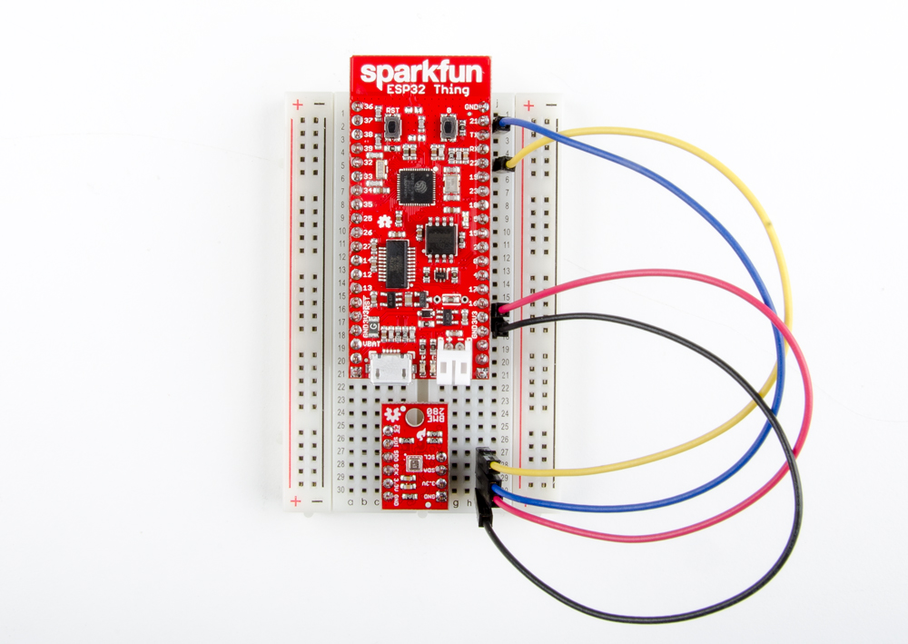
To connect the BME280 to the ESP32, wire up as follows:
| BME280 Pin |
ESP32 Pin |
|---|---|
| SCL | 22 |
| SDA | 21 |
| 3.3V | 3.3V |
| GND | GND |
Then, run the following example.
language:c
/******************************************************************************
BME280_I2C_SPI.ino
BME280 on the ESP32 Thing

Marshall Taylor @ SparkFun Electronics
Original creation date: May 20, 2015
Modified: Nov 6, 2017
https://github.com/sparkfun/ESP32_Motion_Shield

This sketch configures a BME280 to produce comma separated values for use
in generating spreadsheet graphs.

It has been modified from the original BME280 example to demonstrate I2C and
SPI operation on the ESP32 Motion board.

Original source:
https://github.com/sparkfun/SparkFun_BME280_Arduino_Library

Resources:
Uses Wire.h for I2C operation
Uses SPI.h for SPI operation

Development environment specifics:
Arduino IDE 1.8.2

This code is released under the [MIT License](http://opensource.org/licenses/MIT).
Please review the LICENSE.md file included with this example. If you have any questions
or concerns with licensing, please contact techsupport@sparkfun.com.
Distributed as-is; no warranty is given.
******************************************************************************/
#include <stdint.h>
#include "SparkFunBME280.h"

#include "Wire.h"
#include "SPI.h"

#define BME280_CS_PIN 17

//Global sensor object
BME280 mySensor;

unsigned int sampleNumber = 0; //For counting number of CSV rows

void setup()
{
Wire.begin();

// For SPI, enable the "mySensor.beginSPI(10)" line and disable the "mySensor.beginI2C()" line.
if (mySensor.beginI2C() == false) //Begin communication over I2C.
 //if (mySensor.beginSPI(17) == false) //Begin communication over SPI. Use pin 17 as Chip Select.
 {
   Serial.println("The sensor did not respond. Please check wiring.");
while(1); //Freeze
 }


    //***Operation settings*****************************//
    mySensor.settings.runMode = 3; //  3, Normal mode
    mySensor.settings.tStandby = 0; //  0, 0.5ms
    mySensor.settings.filter = 0; //  0, filter off
    //tempOverSample can be:
    //  0, skipped
    //  1 through 5, oversampling *1, *2, *4, *8, *16 respectively
    mySensor.settings.tempOverSample = 1;
    //pressOverSample can be:
    //  0, skipped
    //  1 through 5, oversampling *1, *2, *4, *8, *16 respectively
    mySensor.settings.pressOverSample = 1;
    //humidOverSample can be:
    //  0, skipped
    //  1 through 5, oversampling *1, *2, *4, *8, *16 respectively
    mySensor.settings.humidOverSample = 1;

    Serial.begin(115200);
    Serial.print("Program Started\n");
    Serial.print("Starting BME280... result of .begin(): 0x");
    delay(10);  //Make sure sensor had enough time to turn on. BME280 requires 2ms to start up.
    //Calling .begin() causes the settings to be loaded
    Serial.println(mySensor.begin(), HEX);

    //Build a first-row of column headers
    Serial.print("\n\n");
    Serial.print("Sample,");
    Serial.print("T(deg C),");
    Serial.print("T(deg F),");
    Serial.print("P(Pa),");
    Serial.print("Alt(m),");
    Serial.print("Alt(ft),");
    Serial.print("%RH");
    Serial.println("");

}

void loop()
{

    //Print each row in the loop
    //Start with temperature, as that data is needed for accurate compensation.
    //Reading the temperature updates the compensators of the other functions
    //in the background.
    Serial.print(sampleNumber);
    Serial.print(",");
    Serial.print(mySensor.readTempC(), 2);
    Serial.print(",");
    Serial.print(mySensor.readTempF(), 3);
    Serial.print(",");
    Serial.print(mySensor.readFloatPressure(), 0);
    Serial.print(",");
    Serial.print(mySensor.readFloatAltitudeMeters(), 3);
    Serial.print(",");
    Serial.print(mySensor.readFloatAltitudeFeet(), 3);
    Serial.print(",");
    Serial.print(mySensor.readFloatHumidity(), 0);
    Serial.println();

    sampleNumber++;

    delay(50);

}
SPI
Now wire the BME280 up to the ESP32's SPI port.
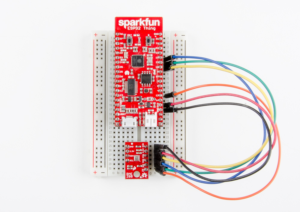
Here are the connections in the picture.
| BME280 Pin |
ESP32 Pin |
|---|---|
| CS | 17 |
| SDI |
23 |
| SDO | 19 |
| SCK |
18 |
| 3.3V | 3.3V |
| GND | GND |
To start the BME280 in SPI mode, we switch the configuration by commenting/uncommenting code as shown in the example below. Otherwise, the code is the same.
language:c
/******************************************************************************
BME280_I2C_SPI.ino
BME280 on the ESP32 Thing

Marshall Taylor @ SparkFun Electronics
Original creation date: May 20, 2015
Modified: Nov 6, 2017
https://github.com/sparkfun/ESP32_Motion_Shield

This sketch configures a BME280 to produce comma separated values for use
in generating spreadsheet graphs.

It has been modified from the original BME280 example to demonstrate I2C and
SPI operation on the ESP32 Motion board.

Original source:
https://github.com/sparkfun/SparkFun_BME280_Arduino_Library

Resources:
Uses Wire.h for I2C operation
Uses SPI.h for SPI operation

Development environment specifics:
Arduino IDE 1.8.2

This code is released under the [MIT License](http://opensource.org/licenses/MIT).
Please review the LICENSE.md file included with this example. If you have any questions
or concerns with licensing, please contact techsupport@sparkfun.com.
Distributed as-is; no warranty is given.
******************************************************************************/
#include <stdint.h>
#include "SparkFunBME280.h"

#include "Wire.h"
#include "SPI.h"

#define BME280_CS_PIN 17

//Global sensor object
BME280 mySensor;

unsigned int sampleNumber = 0; //For counting number of CSV rows

void setup()
{
Wire.begin();

// For SPI, enable the "mySensor.beginSPI(10)" line and disable the "mySensor.beginI2C()" line.
//if (mySensor.beginI2C() == false) //Begin communication over I2C.
if (mySensor.beginSPI(17) == false) //Begin communication over SPI. Use pin 17 as Chip Select.
  {
Serial.println("The sensor did not respond. Please check wiring.");
while(1); //Freeze
  }


    //***Operation settings*****************************//
    mySensor.settings.runMode = 3; //  3, Normal mode
    mySensor.settings.tStandby = 0; //  0, 0.5ms
    mySensor.settings.filter = 0; //  0, filter off
    //tempOverSample can be:
    //  0, skipped
    //  1 through 5, oversampling *1, *2, *4, *8, *16 respectively
    mySensor.settings.tempOverSample = 1;
    //pressOverSample can be:
    //  0, skipped
    //  1 through 5, oversampling *1, *2, *4, *8, *16 respectively
    mySensor.settings.pressOverSample = 1;
    //humidOverSample can be:
    //  0, skipped
    //  1 through 5, oversampling *1, *2, *4, *8, *16 respectively
    mySensor.settings.humidOverSample = 1;

    Serial.begin(115200);
    Serial.print("Program Started\n");
    Serial.print("Starting BME280... result of .begin(): 0x");
    delay(10);  //Make sure sensor had enough time to turn on. BME280 requires 2ms to start up.
    //Calling .begin() causes the settings to be loaded
    Serial.println(mySensor.begin(), HEX);

    //Build a first-row of column headers
    Serial.print("\n\n");
    Serial.print("Sample,");
    Serial.print("T(deg C),");
    Serial.print("T(deg F),");
    Serial.print("P(Pa),");
    Serial.print("Alt(m),");
    Serial.print("Alt(ft),");
    Serial.print("%RH");
    Serial.println("");

}

void loop()
{

    //Print each row in the loop
    //Start with temperature, as that data is needed for accurate compensation.
    //Reading the temperature updates the compensators of the other functions
    //in the background.
    Serial.print(sampleNumber);
    Serial.print(",");
    Serial.print(mySensor.readTempC(), 2);
    Serial.print(",");
    Serial.print(mySensor.readTempF(), 3);
    Serial.print(",");
    Serial.print(mySensor.readFloatPressure(), 0);
    Serial.print(",");
    Serial.print(mySensor.readFloatAltitudeMeters(), 3);
    Serial.print(",");
    Serial.print(mySensor.readFloatAltitudeFeet(), 3);
    Serial.print(",");
    Serial.print(mySensor.readFloatHumidity(), 0);
    Serial.println();

    sampleNumber++;

    delay(50);

}
Using the GPS Port
The GPS port is just a pass-through to the serial port, so configuration is easy. Simply start the serial port at the desired baud, usually 9600.
This example simply passes serial monitor data to the GPS port, and GPS data to the serial monitor. Set the serial speeds when calling begin. Serial is the USB serial port, and GPSUART is the GPS port.
language:c
#include <Arduino.h>
HardwareSerial GPSUART(2);  // Set up GPS UART on pins 16 & 17

void setup()
{
  Serial.begin(115200);
  GPSUART.begin(9600);
  delay(1000);
  Serial.println("Sketch Started.");
}

void loop() {
  //Pass usb data to the gps
  if (Serial.available())
  {
    GPSUART.write(Serial.read());
  }
  //Pass gps data to the usb
  if (GPSUART.available())
  {
    Serial.write(Serial1.read());
  }
}
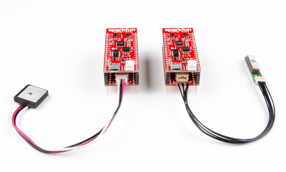
As for the hardware, either plug in the recommend 3-wire GPS module (rx only), or wire in a 4-wire module (that can be run from 3.3V) to the provided pin header.
The data that the GPS will emit comes in the form of NMEA messages. See the NMEA Reference Manual (PDF) for information on decoding.
Logging a Journey
Putting all the concepts from this hookup guide together, a data logger can be built that saves IMU and GPS data. For your consideration, a simple example exists in the software folder of the Motion Shield's GitHub repository.
The program collects the GPS data as strings of NMEA data, and the IMU data as CSV. It uses the FileSerial library to create two sets of files, one for GPS data and one for IMU data. What to do with the data is up to you, but let's take a look at the GPS data and graph it.
This is what the GPS NMEA messages look like:
The data is given to a tool such as the GPS Visualizer, which can create various types of data. Outputting as GPX format, the data can be passed to a map web application.
And finally, the GPS track can be viewed.
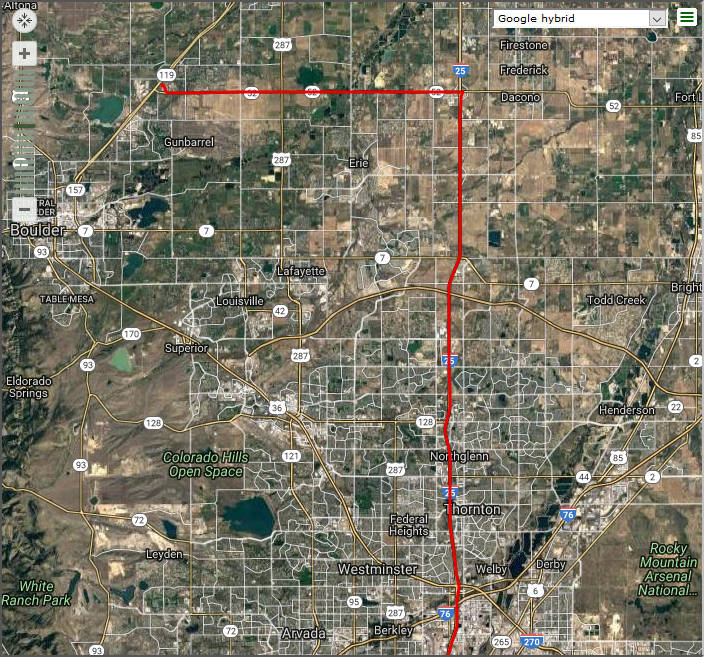
GPS Visualizer can also produce data that can be used in Google Earth, and has a bunch of options. If you've never used GPS data before, it can be super helpful to demystify all the terminology.
Resources and Going Further
Now that you've explored all the aspects of the Motion Shield, it's time to duct tape the Thing to your cat to see just where they really go at night. I hope you don't really do that, but if you wanted to, these links may help you get closer to your goal.
For more information, check out the resources below:
- Schematic (PDF) - ESP32 Thing Motion Shield's schematic.
- Eagle Files (ZIP) - Board layout files.
- LSM9DS1 Datasheet (PDF) - Datasheet for the LSM9DS1 sensor.
- SparkFun Product Showcase: ESP32 Thing Motion Shield
- GitHub: ESP32_Motion_Shield -- Product repository.
- GitHub: ESP32_Motion_Shield/Software -- Software examples (from within product repository).
- Arduino Libraries:
- LSM9DS1 -- Follow the LSM9DS1 Hookup Guide or use the library manager.
- BME280 -- Follow the BME280 Hookup Guide or use the library manager.
- ESP32 Thing Hookup Guide -- Information about the ESP32 Thing board.
- ESP32 Thing Hookup Guide: Resources and Going Further -- Additional resources and going further with the ESP32.
Need some inspiration for your next project? Check out some of these related tutorials:
Basic Autonomous Kit for Sphero RVR Assembly Guide
SparkFun GPS NEO-M9N Hookup Guide
Setting up a Rover Base RTK System
How to Build a DIY GNSS Reference Station
Or check out this blog post for ideas: