ESP32 Relay Web Server
 Elias The Sparkiest
 Hardware Assembly - ESP32 Web Server and Quad relay
Hardware for the web server:
The parts I'm using for this part of the project are the following (not listed is the lamp).


Qwiic Cable - 200mm
PRT-14428
SparkFun Qwiic Quad Relay
COM-16566Hardware Hookup
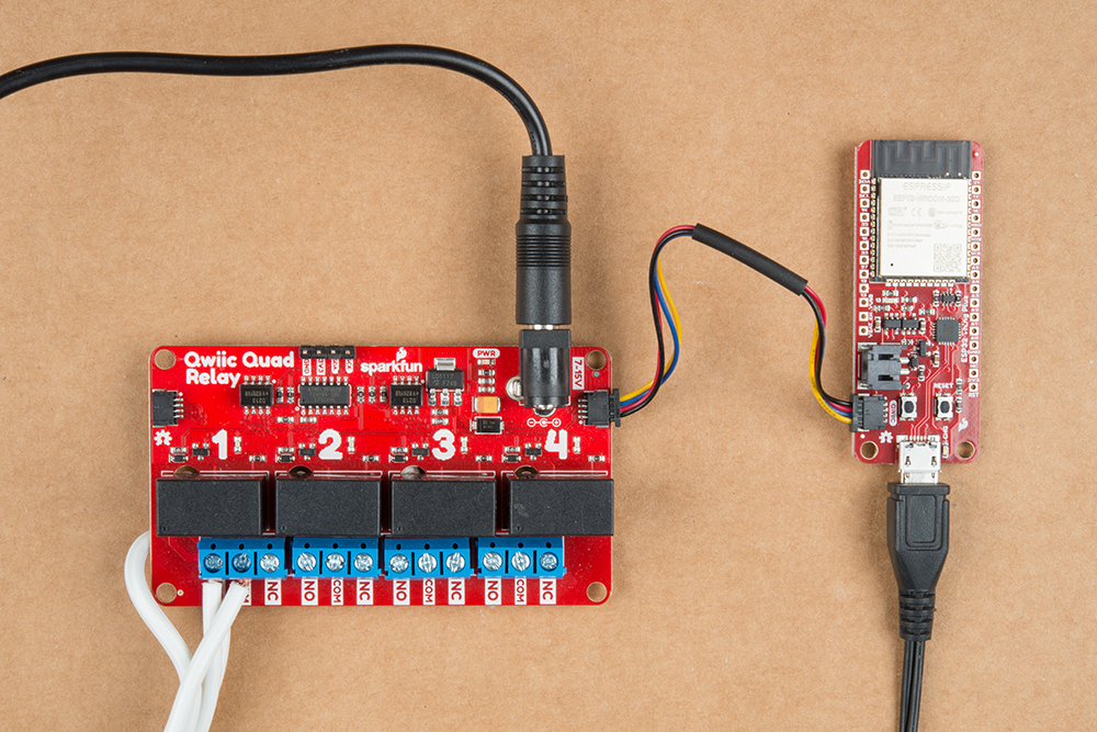
Here we get to cheat a bit because we're using Qwiic capable boards. Power needs to be provided to the ESP32, to the relays on the Qwiic Quad Relay, to the IC on the Qwiic Quad Relay, and an I2C connection needs to be made as well. Wall warts are providing power to both the relays on the Qwiic Quad Relay and to the ESP32 in the image below. Then, to provide power and establish a connection over I2C between the Qwiic Quad Relay and the ESP32, a Qwiic cable is used. No soldering necessary, very very nice.
Not listed is the connection from the relay to the lamp. First, a short review on relays.
How does a relay work?
Simply put, relays are switches. However, they are switches utilizing the magnetic property of electricity to allow the switch to be separate from what flips it. This is the root of what makes them so special - utilizing a low voltage system (3.3V in this case) a person can control the electricity coming out of the wall and to a device like a lamp! Relays are differentiated by how much voltage is needed to flip the switch, and how much power can travel across the switch when it's flipped (some combination of voltage and current). The relays on the Qwiic Quad relay can handle five amps at 250V AC and requires at least 3.3V to flip the switch.
Lamp hookup
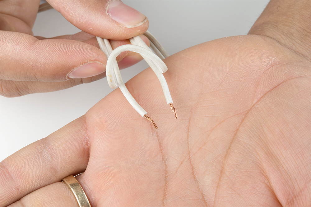
To hookup the lamp to the Qwiic Quad Relay, one of the connections from the lamp will have to be broken so that it can later be closed by the relay when we turn it on. To do that, cut one side of the cable and then strip the cable to expose the protected wire underneath.

Now peel the wire apart and strip the two ends.
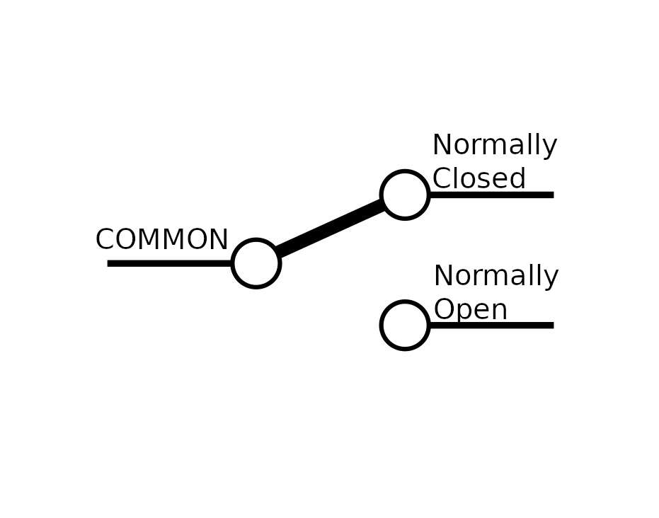
Put one of the ends in the Common (COM) input of the screw terminal and the other end in the Normally Open (NO) input. The common input is the center of our switch, and the normally open input is the end of the switch that will be closed when the switch is flipped. The image below should help clear any confusion.
That's it!