AVR-Based Serial Enabled LCDs Hookup Guide
 QCPete
Troubleshooting
Random Character
If the display is powered up without the RX line connected to anything, the display may fill with strange characters. This is because the display is receiving random noise on the disconnected line. If you connect the RX line to a true TX port, this will not happen.
Faded Characters on Display
If the display is unreadable or washed out, the contrast may need to be adjusted. This is done in software, so you will need to send your display some contrast control commands via Serial UART, I2C or SPI. There is a specific example for each of these communication types inside the github repository here:
- Example2_Serial_Contrast
- Example2_I2C_Contrast
- You can also follow along with the example in this tutorial above: click here.
Emergency Reset
If your LCD screen has entered an unknown state, or you are unable to communicate with it, it's probably a good idea to try resetting everything back to default settings. The OpenLCD firmware has a built-in "emergency reset" feature. When the screen first boots up, the AVR on the back will watch its RX pin. If that pin is held LOW (aka tied to ground), for 2 seconds, then it will reset all settings to default. Most importantly, your baud rate will be set back to 9600. After the reset is complete, the screen will display the message "System Reset Power Cycle Me", and flicker the backlight on and off repeatedly until you cycle power.
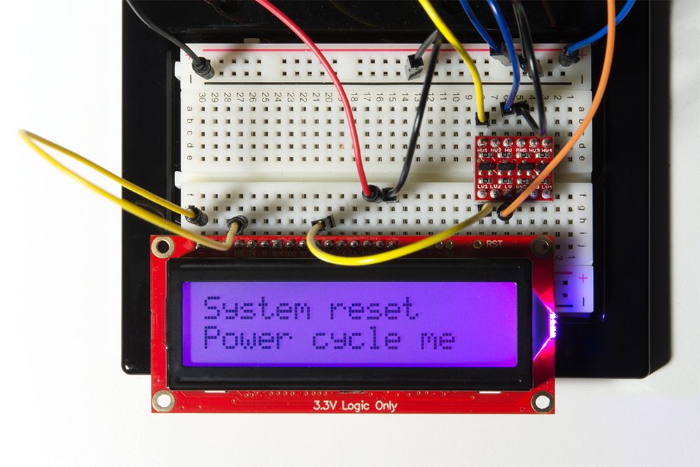
To perform an emergency reset, please be sure to follow these exact steps in this order:
- Ensure your screen is OFF.
- Tie RX to GND.
- Power your screen.
- Wait 2 seconds. Verify "System Reset" message.
- Remove connection from RX to GND.
- Cycle Power.
Now, please enjoy your default settings (including 9600 baud).
Firmware Update
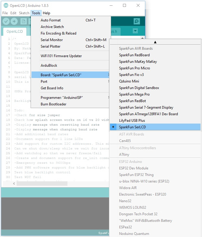
To update the firmware on your LCD, you can use an FTDI Basic 3.3V - beefy model and the Arduino IDE software. The AVR on the back of your LCD actually has an Arduino-compatible bootloader. That said, it is slightly custom in that it was compiled for the 11.0592 crystal. This means you will need to install the SparkFun AVR Boards, and then select "Sparkfun SerLCD" as your board type.
Install the Board Package
If you've made it this far, presumably you have the latest version of the Arduino IDE on your desktop. If you do not, please review our tutorial on installing the Arduino IDE for board add-ons. Here's the tutorial for installing custom board packages:
Once you have that installed, you should see "SparkFun SerLCD" as a board option from the drop down menu here:
Hardware Hookup
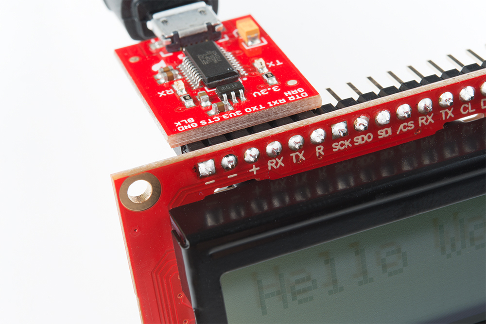
Now plug in your serial FTDI basic into your LCD screen.
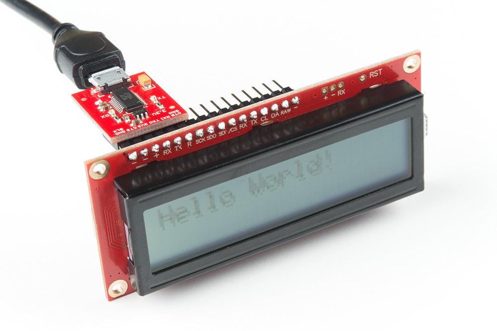
Make sure to line it up properly so the "-" is lined up withe the "GND", and the "R" is lined up with "DTR".
| AVR Programmer Pins | SerLCD Pins | External Power Source for Target (assuming the AVR Programmer is not able to power the target) |
| RAW | 5V | |
| Vcc | Vcc | |
| GND | GND | GND |
| COPI | SDI | |
| CIPO | SDO | |
| SCK | SCK | |
| RESET | RST |
Default Firmware
Download and unzip the latest firmware located in the OpenLCD GitHub repository:
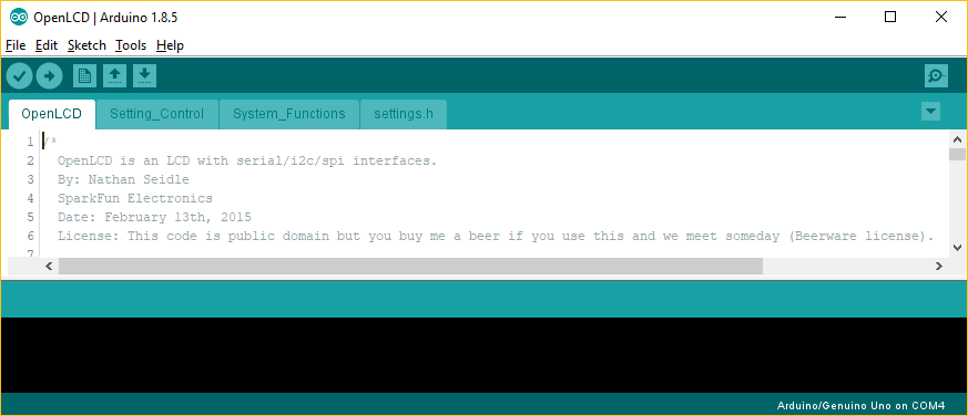
Not that you will need to include all of the files in the "... > OpenLCD-master > firmware > OpenLCD" directory. When you open the OpenLCD.ino sketch in arduino, the other necessary files will open as tabs.
- OpenLCD.ino
- Setting_Control.ino
- System_Functions.ino
- settings.h
SoftPWM and LiquidCrystalFast Arduino Libraries
You will also need to install the SoftPWM and LiquidCrystalFast libraries. You will need to download and manually install the libraries the following libraries before you are able to upload the default firmware. To use these libraries, you can add the library from the Arduino IDE by selecting Sketch > Include Library > Add .ZIP Library… and selecting the .zip file from wherever you store your file downloads.
Uploading Default Firmware
Once the board add-on and associated libraries are installed, click the UPLOAD button in the IDE (the right facing arrow) to get the latest code onto your LCD!
Using the Serial Enabled LCD on an Atmega32U4's Hardware UART
If you are using the serial enabled LCD with an Atmega32U4-based Arduino (like a Pro Micro, Arduino Leonardo, Arduino LilyPad USB, etc), you might need to add a small delay in the setup before you can get it working with the hardware UART (pins 0 and 1). Here's an example:
language:cpp
///test example using ATmega32U4's hardware UART and delay
void setup() {
  delay(2000);//add delay so the ATmega32U4 can have a second before sending serial data to the LCD
  Serial1.begin(9600);//set up the hardware UART baud
}

void loop() {
  Serial1.print("print something");//send something to the serial enabled LCD
  delay(50);
}
Software Serial for Arduino Due
Unfortunately, you are not able to use the serial enabled LCDs with an Arduino Due due the differences in how change interrupts are used for the ARM processor. The software serial library is not included in the Arduino Due's tree:
Try using the other hardware serial UARTs that are not connected to the Arduino Due's programming pins for uploading. Make sure to adjust the code for the hardware serial UART.