AVR-Based Serial Enabled LCDs Hookup Guide
 QCPete
Serial UART: Example Code - Contrast Control with a Trimpot
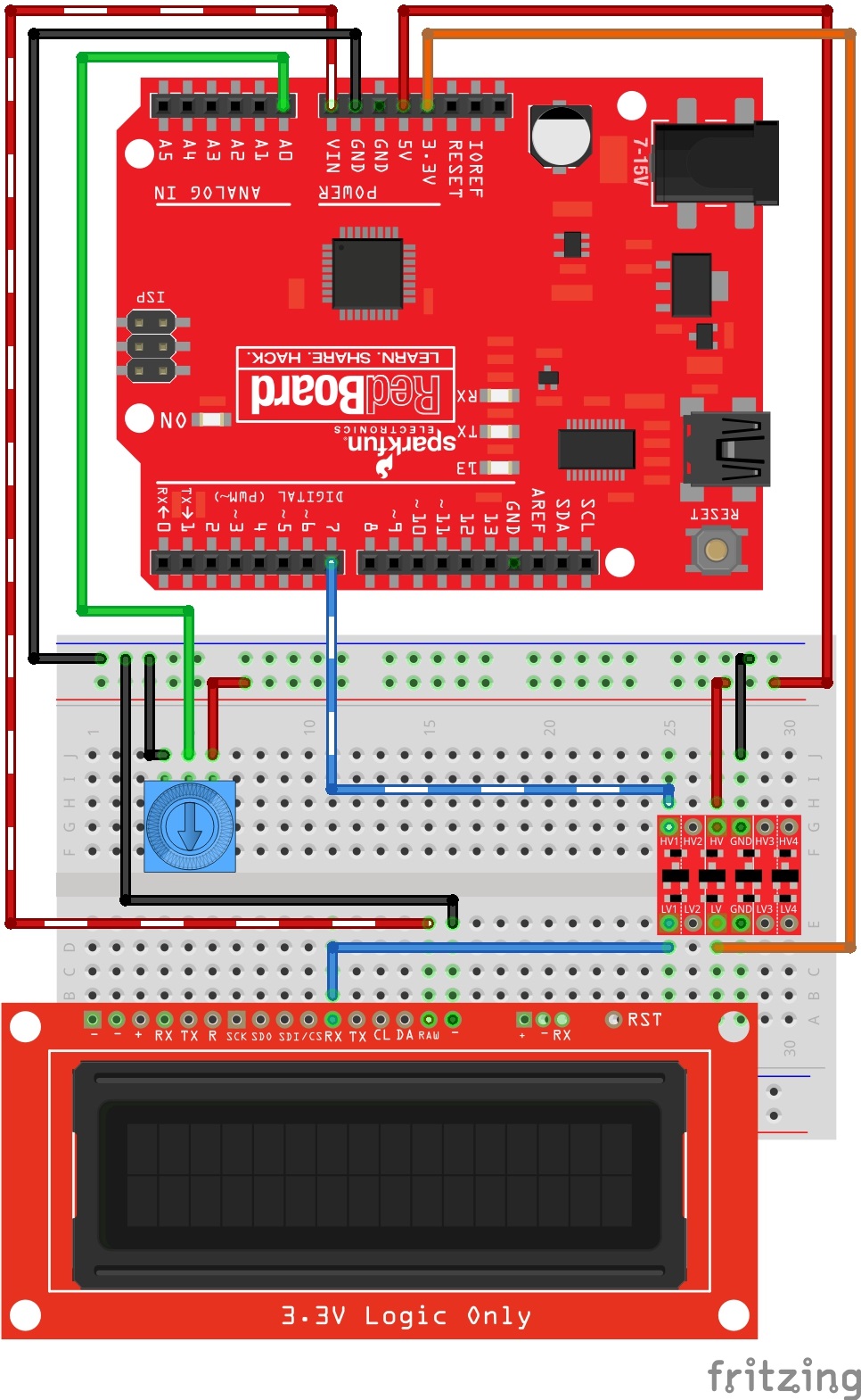
For this contrast control example, you will need to wire up a trimpot. This will allow you to adjust the contrast in real time and find the best setting for your environment. Wire things up like this:
You can download the latest example code for this experiment from the GitHub repo or you can copy and paste the following code into your Arduino IDE:
language:cpp
 /*
 OpenLCD is an LCD with Serial/I2C/SPI interfaces.
 By: Nathan Seidle
 SparkFun Electronics
 Date: April 19th, 2015
 License: This code is public domain but you buy me a beer if you use this and we meet someday (Beerware license).

 OpenLCD gives the user multiple interfaces (serial, I2C, and SPI) to control an LCD. SerLCD was the original
 serial LCD from SparkFun that ran on the PIC 16F88 with only a serial interface and limited feature set.
 This is an updated serial LCD.

 This example shows how to change the contrast using a trimpot. We assume the module is currently at
 default 9600bps.

 We use software serial because if OpenLCD is attached to an Arduino's hardware serial port during bootloading
 it can cause problems for both devices.

 Note: If OpenLCD gets into an unknown state or you otherwise can't communicate with it send 18 (0x12 or ctrl+r)
 at 9600 baud while the splash screen is active and the unit will reset to 9600 baud.

 Emergency reset: If you get OpenLCD stuck into an unknown baud rate, unknown I2C address, etc, there is a
 safety mechanism built-in. Tie the RX pin to ground and power up OpenLCD. You should see the splash screen
 then "System reset Power cycle me" and the backlight will begin to blink. Now power down OpenLCD and remove
 the RX/GND jumper. OpenLCD is now reset to 9600bps with a I2C address of 0x72. Note: This feature can be
 disabled if necessary. See *Ignore Emergency Reset* for more information.

 To get this code to work, attached an OpenLCD to an Arduino Uno using the following pins:
 RX (OpenLCD) to Pin 7 (Arduino)
 VIN to 5V
 GND to GND

 Hook a trimpot up:
 Pin 1 - 5V
 Pin 2 - A0
 Pin 3 - GND

*/

#include <SoftwareSerial.h>

SoftwareSerial OpenLCD(6, 7); //RX (not used), TX

byte counter = 0;

void setup()
{
  Serial.begin(9600); //Start serial communication at 9600 for debug statements
  Serial.println("OpenLCD Example Code");

  OpenLCD.begin(9600); //Begin communication with OpenLCD

  //Send the reset command to the display - this forces the cursor to return to the beginning of the display
  OpenLCD.write('|'); //Send setting character
  OpenLCD.write('-'); //Send clear display character
  OpenLCD.print("Contrast test");

  pinMode(A0, INPUT);
}

int oldContrast = 0;
long startTime = 0;
bool settingSent = false;

void loop()
{
  int trimpot = averageAnalogRead(A0);
  int newContrast = map(trimpot, 0, 1023, 0, 255); //Map this analog value down to 0-255

  //Only send new contrast setting to display if the user changes the trimpot
  if(newContrast != oldContrast)
  {
    Serial.print("nc: ");
    Serial.println(newContrast);

    oldContrast = newContrast; //Update

    startTime = millis();
    settingSent = false;
  }

  //Wait at least 100ms for user to stop turning trimpot
  //OpenLCD displays the contrast setting for around 2 seconds so we can't send constant updates
  if(millis() - startTime > 500 && settingSent == false)
  {
    //Send contrast setting
    OpenLCD.write('|'); //Put LCD into setting mode
    OpenLCD.write(24); //Send contrast command
    OpenLCD.write(newContrast);

    settingSent = true;

    Serial.print("New contrast: ");
    Serial.println(newContrast);
  }

  delay(100); //Hang out for a bit
}

//Takes an average of readings on a given pin
//Returns the average
int averageAnalogRead(byte pinToRead)
{
  byte numberOfReadings = 8;
  unsigned int runningValue = 0;

  for(int x = 0 ; x < numberOfReadings ; x++)
    runningValue += analogRead(pinToRead);
  runningValue /= numberOfReadings;

  return(runningValue);
}
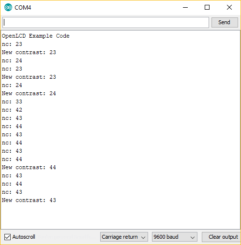
After uploading your sketch, you can now try adjusting the trimpot and watch the contrast change in real time. Here are a few examples that I see:
 |
 |
 |
| Contrast Setting: 0 | Contrast Setting: 55 | Contrast Setting: 80 |
Note, if you are not seeing any text in the LCD, make sure and try rotating to either extreme. If you are up above 100, then in some cases you may not see any text. Watching your serial monitor from your Arduino can be helpful as well. It will tell you the settings as you are sending them to the LCD. Here is some example serial debug that I see while I adjust the trimpot: