AVR-Based Serial Enabled LCDs Hookup Guide
 QCPete
 Hardware Overview
Features
The AVR-based SerLCD has many features that make it powerful and economical:
- Qwiic connector allows for single cable solution that provides connections for both power and I2C communication lines.
- AVR microcontroller utilizes 11.0592 MHz crystal for greater communication accuracy
- Adjustable baud rates of 1200, 2400, 4800, 9600 (default), 14400, 19200, 38400, 57600, 115200, 230400, 460800, 921600, 1000000
- The AVR ATmega328P (with Arduino-compatible bootloader) is populated on the back of each LCD screen and handles all of the LCD control
- 3 communication options
- Serial UART, I2C and SPI
- Adjustable I2C address controlled via software special commands (0x72 default)
- Emergency reset to factory settings (Jumper RX to GND on bootup)
- Operational backspace character
- Incoming buffer stores up to 80 characters
- Pulse width modulation of backlight allows direct control of backlight brightness and current consumption
- Pulse width modulation of contrast allows for software defined contrast amount. The previous backpack versions of this product required adjusting the contrast via a hardware trim-pot which was less precise and less accessible in most enclosed projects.
- User definable splash screen
- Open-sourced firmware and Arduino-compatible bootloader enables updates via the Arduino IDE
- Input voltage: 3.3V-9V (3.3V only via Qwiic connector and "+" pin)
- I/O logic levels: 3.3V
- Current consumption @ 3.3V
- 16x2 SerLCD with RGB backlight
- minimum with no characters
- 4.4mA (LEDs off)
- maximum with all character spaces filled
- 11.9mA (red)
- 8.9mA (green)
- 8.1mA (blue)
- 19.6mA (white)
- minimum with no characters
- 20x4 SerLCD with RGB backlight
- minimum with no characters
- 4.5mA (LEDs off)
- maximum with all character spaces filled
- 21.7mA (red)
- 17.2mA (green)
- 15.5mA (blue)
- 41.1mA (white)
- minimum with no characters
- 16x2 SerLCD with RGB backlight
AVR-Based Serial Controller (3.3V Logic Only)
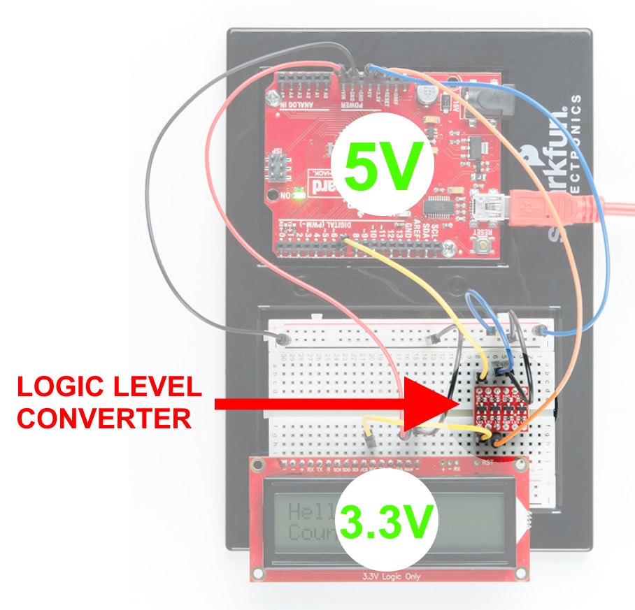
Using these screens, it is easy to connect to any microcontroller that has a serial UART, I2C, or SPI. If you are using Qwiic to control your screen, then all you need is a qwiic cable. However, if you choose to use something other than Qwiic (with connections located on the PTH headers), then please make sure you convert to 3.3V Logic! In the example below, we chose to use our 5V RedBoard with a Logic Level Converter.
Connection Options
The latest versions of the SerLCD have a qwiic connector on the back.
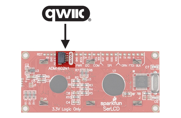
All Qwiic compatible products operate their I2C on the cable at a logic level of 3.3V, and so no conversion is necessary. Also note, the connector is a right-angled syle connector, so that if your project does not have much space on the back side of the screen, then you can exit your cable with a lower profile. We did not put it exiting on the edge of the board (as most Qwiic products do), so that if your project and/or enclosure is tight on the sides of the screen, the Qwiic cable will not conflict.
Both sizes of these screens (16x2 and 20x4) have a row of headers along the top side. This is where you can connect power and your choice of communication protocol (Serial UART, I2C, or SPI). It also has our 6-pin Arduino Serial port available for convenient firmware updates.
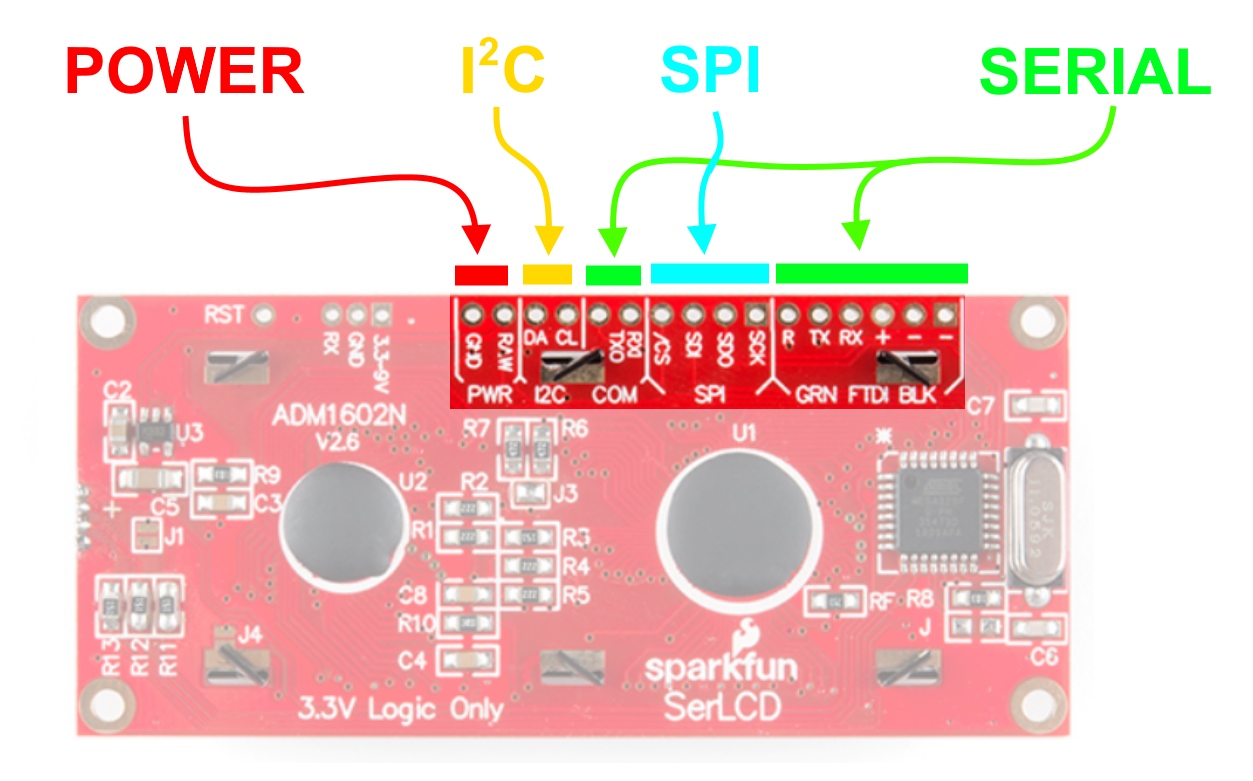
Note, if you choose Serial UART, there is a handy 3-pin JST footprint. This includes the minimum connections needed: RX, GND and VIN. Our JST Jumper 3 Wire Assembly is a good way to go:
 |
 |
| Location on screen | JST Jumper 3 Wire Assembly |
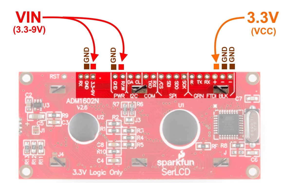
Input Voltage (VDD) and Logic Levels
All of these screens can be powered by 3.3-9V. You have two pin options for connecting up power. One is labeled "RAW" and the other (on the 3-pin JST) is labeled "3.3-9V". Note, the pin labeled "+" is NOT a power input pin! This is connected to the VCC of the ATmega329P (3.3V).
Pro tip: If you plan to run 100% brightness on all three colors (red, green, blue), then it would be best to keep your power input voltage low. As close to 3.3V as possible is best. This will keep the on-board linear 3.3V voltage regulator nice and cool. It can accept up to 9V and power all three backlights at 100%, but it will get a little warm, and over years of use, potentially damage the vreg. For more information about vregs and why they heat up sometimes, please check out our tutorial: Power and Thermal Dissipation
Contrast Control
The on-board ATmega328P controls the contrast of the screen using a PWM signal. This can be adjusted by sending a command via Serial UART, I2C, or SPI. The screens ship out with the contrast setting set to 10, which we have found works well for most environments. Temperature and supply voltage can affect the contrast of the LCD, so you may need to adjust it accordingly. For more info about contrast and a detailed example, please see the section below called: Serial UART: Example Code - Contrast Control with a Trimpot.
Current Consumption
The following current measurements were taken from a basic multimeter. This assumes that:
- system messages are disabled
- contrast is set to
5 - SerLCDs are being powered off the RedBoard Qwiic's 3.3V voltage regulator via I2C
- all character spaces are set to black rectangles █ as the "text"
- measurements between each color had 5000ms to let the SerLCD settle before the next color change
- continuously cycling colors had the backlight changing about every 50ms
| 16x2 SerLCD w/ RGB Backlight Current Consumption |
||
| LED Color | no text | text |
|---|---|---|
| off | 4.4mA | 4.4mA |
| red | 11.9mA | 11.9mA |
| green | 8.9mA | 8.9mA |
| blue | 8.1mA | 8.1mA |
| white | 19.6mA | 19.6mA |
| cycling colors | 15.6mA | 15.6mA |
| 20.4 SerLCD w/ RGB Backlight Current Consumption |
||
| LED Color | no text | text |
|---|---|---|
| off | 4.5mA | 4.5mA |
| red | 21.6mA | 21.7mA |
| green | 17.2mA | 17.2mA |
| blue | 15.4mA | 15.5mA |
| white | 41.0mA | 41.1mA |
| cycling colors | 30.1mA | 30.8mA |
Dimensions
If you plan to mount a SerLCD into your project, please take a look at the following dimensional drawings. We have provided them in both PDF and PNG file format for both the 16x2 and the 20x4 Qwiic versions. Also, note that the tolerances of manufacturing are not always perfect, so please allow for some buffer room if designing around these numbers. Otherwise, your enclosure may be too tight or possibly not fit at all.
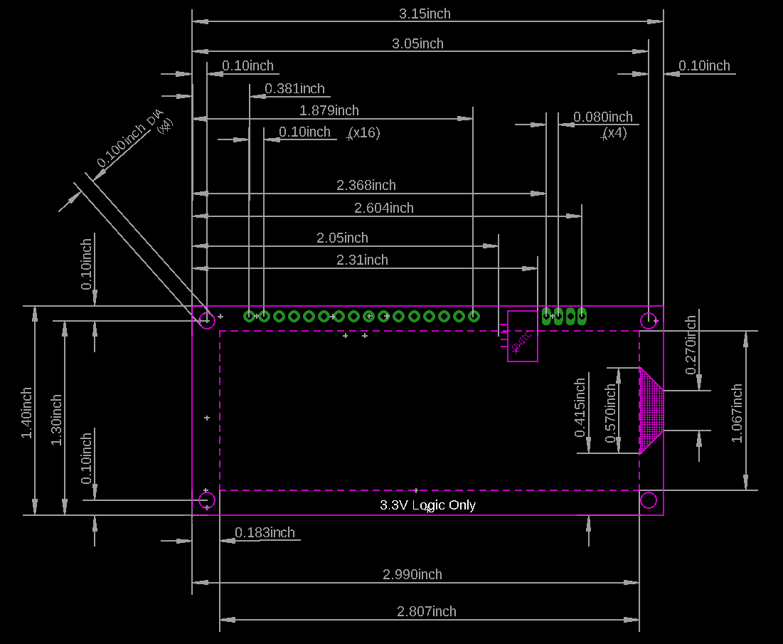
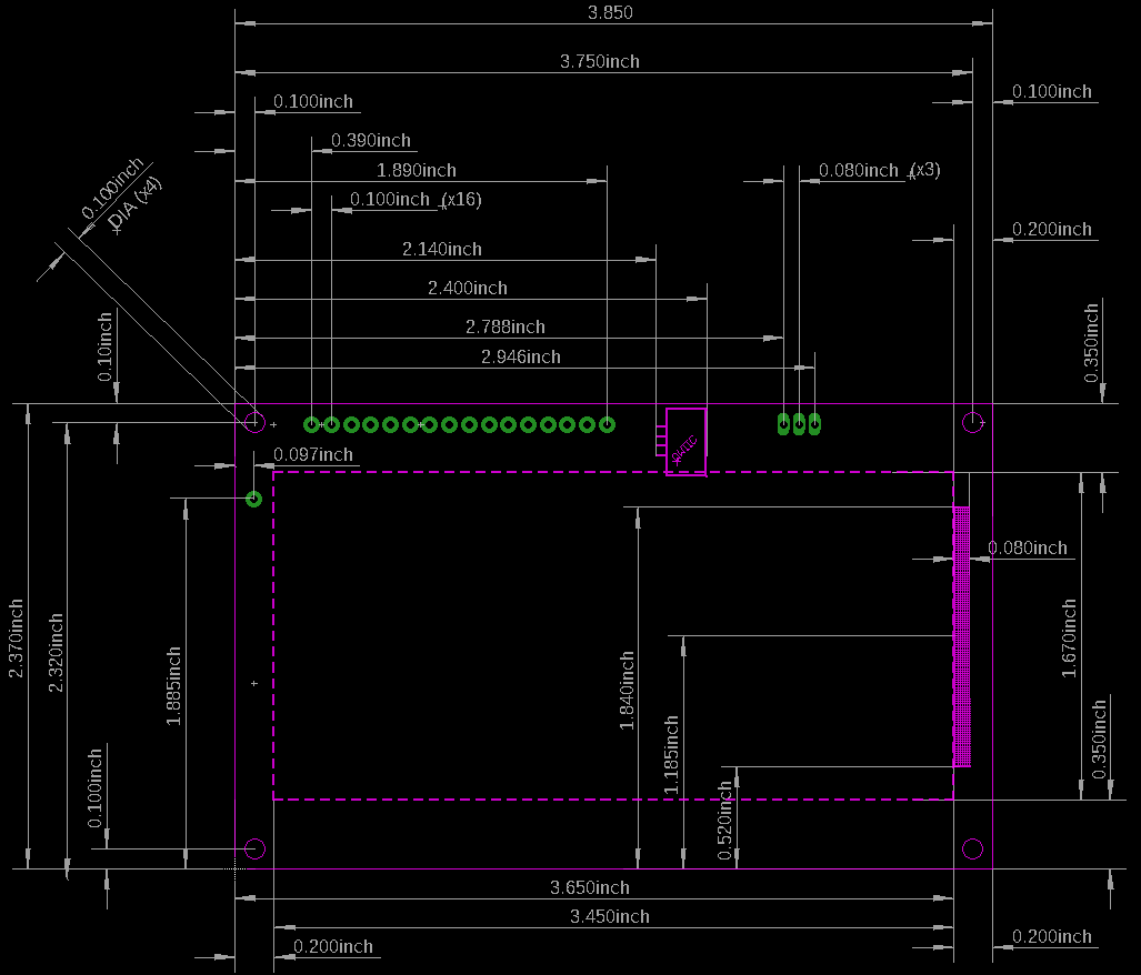
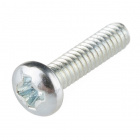
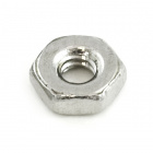
Also note, the standoff holes on these screens do not fit our 4-40 sized screws or hex metal standoffs. You will need to use something slightly smaller in diameter, like our 2-56 screws and metal nut.
If you would like to include an LCD as a device in your eagle design, then you will find the SparkFun-boards.lbr very useful. It is located in the larger github repository that contains all of the SparkFun Eagle Libraries.
Inside the library you will find the SER_LCD_QWIIC devices that allow you to simply drop this into your design and start netting/routing as desired!
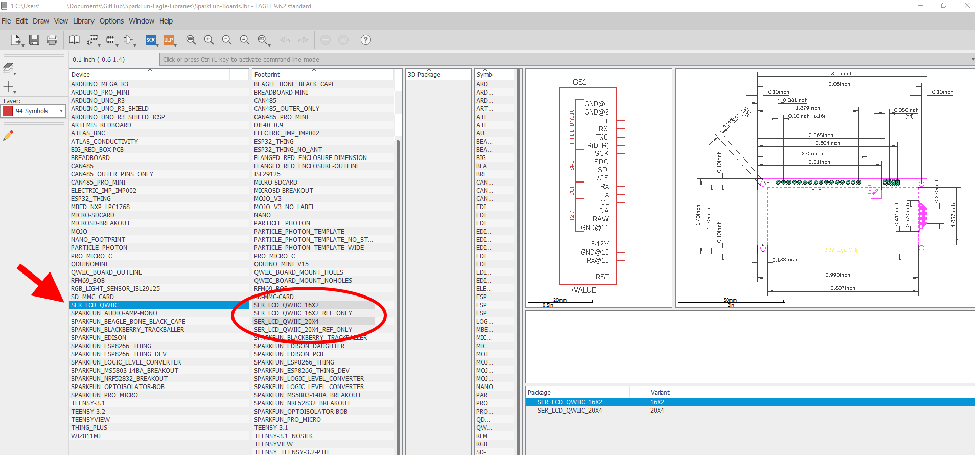
As another option, we have included footprints that have only the reference layers, with no electrical connections (that is, no device with a symbol and linked pins/pads).
") |
") |
| SER_LCD_QWIIC_16X2_REF_ONLY.fpt | SER_LCD_QWIIC_20X4_REF_ONLY.fpt |
These "reference only" footprints are useful for dropping into a design and then quickly knowing the location of your standoff holes, the screen, the qwiic connector and such. If you plan to use the qwiic connection, but still want to mount a SerLCD into your PCB design, the "reference only" footprints are the best option. You can add these as a part directly into your board editor, and you'll be ready to drop in standoff holes and start designing.