PIC-Based Serial Enabled Character LCD Hookup Guide
 bboyho,
  MikeGrusin
 Introduction
The PIC-based serial enabled character LCD (a.k.a. SerLCD) backpack is a simple and cost effective solution for interfacing to character Liquid Crystal Displays (LCDs) based on the HD44780 controller. The backpack simplifies the number of wires needed and allows your project to display all kinds of text and numbers.
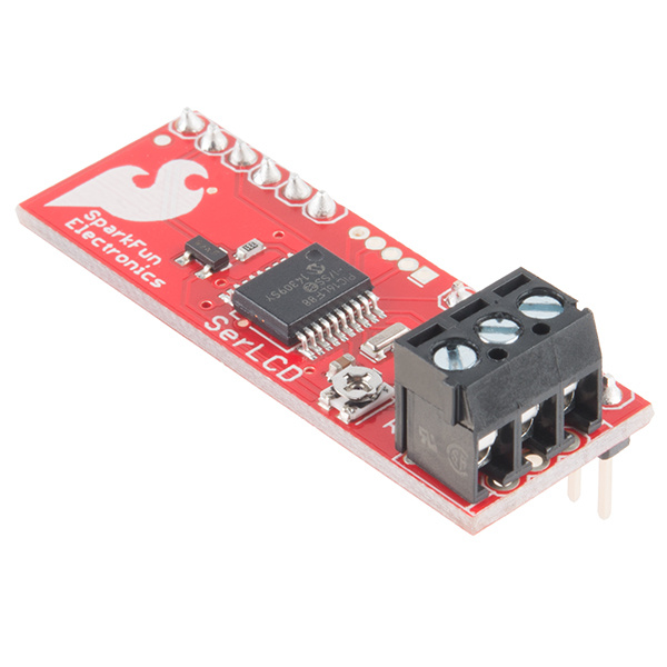
SparkFun Serial Enabled LCD Backpack
LCD-00258The SerLCD backpack can also be found on a variety of serial enabled character LCDs with different color schemes, sizes, and input voltages. In this tutorial, we will connect to a serial enabled LCD and send ASCII characters to the display using an Arduino microcontroller.
Required Materials
To follow along with this tutorial, you will need the following materials at a minimum. Depending on what you have, you may not need everything on this list. Add it to your cart, read through the guide, and adjust the cart as necessary.
Tools
You may need a soldering iron, solder, and general soldering accessories, and screw driver depending on your setup.


Weller WLC100 Soldering Station
TOL-14228Suggested Reading
If you aren’t familiar with the following concepts, we recommend checking out these tutorials before continuing.
How to Solder: Through-Hole Soldering
Serial Communication
What is an Arduino?
Installing Arduino IDE
Logic Levels
ASCII
Basic Character LCD Hookup Guide
Hardware Overview
SerLCD v2.5 has some new features that make the SerLCD even more powerful and economical:
- PIC microcontroller utilizes onboard UART for greater communication accuracy
- The PIC16LF88 is populated on the SerLCD backpack
- The PIC16F88 is populated on the built-in serial enabled LCDs
- Adjustable baud rates of 2400, 4800, 9600 (default), 14400, 19200 and 38400
- Operational backspace character
- Incoming buffer stores up to 80 characters
- Backlight transistor can handle up to 1A and can be connected to external loads
- Pulse width modulation of backlight allows direct control of backlight brightness and current consumption
- User definable splash screen
PIC-Based Serial Controller
Using the serial enabled controller, it is easy to connect to any microcontroller that has a serial UART port such as an Arduino, AVR, PIC, etc. The SerLCD supports 16 and 20 character-wide screens with 2 or 4 lines of display.
 |
 |
| RedBoard Connected to a Basic Character LCD in Parallel | RedBoard Connected to Serial Enabled LCD |
Input Voltage (VDD) and Logic Levels
Depending on your LCD's specs, the input voltage may be 3.3V or 5V. For the LCDs listed below, the input voltage for the backpack must be 3.3V even though the silkscreen says 5V. The logic levels will be the same as the input voltage.

The LCDs listed below require an input voltage of 5V. Higher than 5.5V will cause damage to the PIC, LCD, and backlight (if attached). At 5V, the SerLCD uses 3mA with the backlight turned off and ~60mA with the backlight activated. The following LCDs do not have a SerLCD backpack.

The following LCDs have a backpack built into the board.
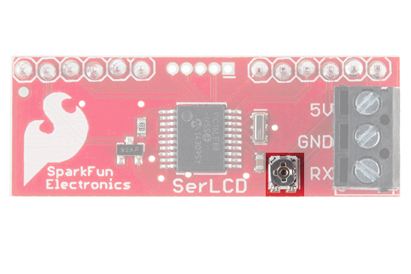
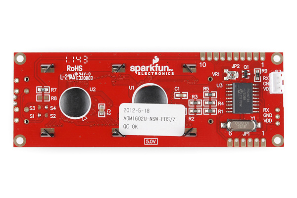
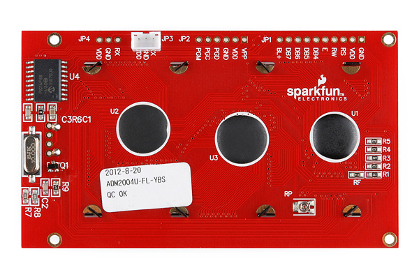
Contrast Control
The SerLCD and built-in serial LCDs comes equipped with a 10k potentiometer to control the contrast of the LCD. This is set during assembly and testing but may need correcting for your specific LCD module. Temperature and supply voltage can affect the contrast of the LCD. While powered, simply adjust the potentiometer with a screw driver.
 |
 |
 |
| SerLCD Backpack | Serial Enabled LCD 16x2 | Serial Enabled LCD 20x4 |
Hi-Current Control Pin
The SerLCD v2.5 uses a general purpose, 1000mA NPN transistor to control the LCDs backlight. If you purchased the SerLCD module, you may use this pin as a general purpose, high power control pin. If you issue the backlight on/off command to the SerLCD or built-in serial LCD, the BL pin on the board can also be used to power / control other circuits with a maximum current of 1000 mA. This is usually the last pin on the top row of the LCD. Check your datasheet for proper pin outs.
 |
 |
 |
| SerLCD Backpack | Serial Enabled LCD 16x2 | Serial Enabled LCD 20x4 |
Hardware Hookup
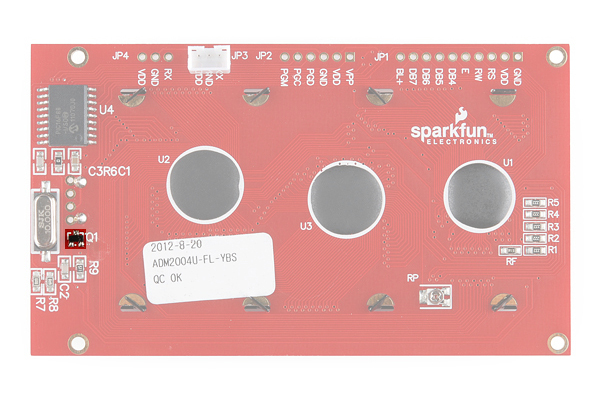
Assembling the SerLCD Backpack
Insert the SerLCD backpack's long end of the headers through the back of a basic LCD. Solder the header on the top side of the LCD. The LCD should look like the images below after the terminals are cleaned (assuming that you are using water-soluble flux). If you are using the through holes under the screw terminals, make sure to solder to the pins before assembling the backpack to the basic LCD.
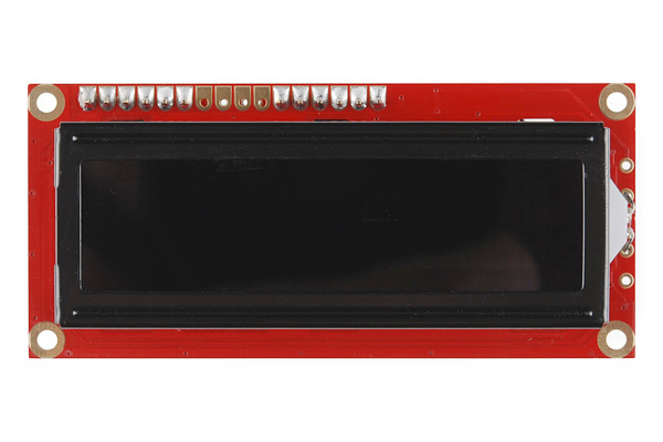 |
 |
| Top View | Bottom View |
Connecting to an Arduino
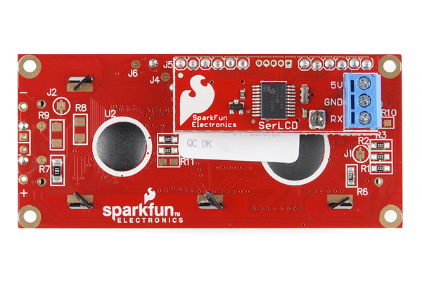
To power and control a serial enabled LCD, you will need three pins. There are two rows of headers broken out on the backpack and built-in serial enabled LCDs. They are electrically identical, so you can use either one. The SerLCD backpack comes pre-populated with a 3-pin screw terminal. Simply insert M/M jumper wire to each of the screw terminals and tighten. You can also solder directly to the plated through holes on the bottom of the backpack.
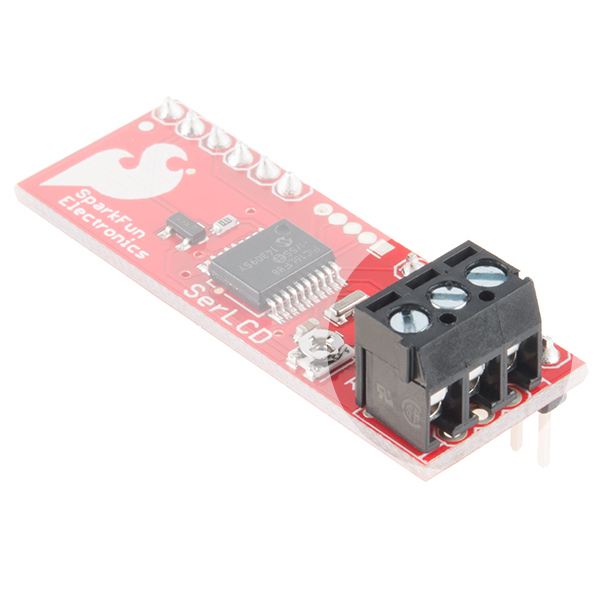 |
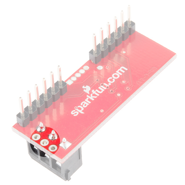 |
| Screw Terminals | Plated Through Holes |
Instead of a screw terminal, the built-in serial enabled LCDs come pre-populated with a 3-pin polarized JST connector. The JST to breadboard jumper would be the easiest to connect to an Arduino. The cable only connects one way; press it in until it clicks. JST connectors are designed to be very snug; don't pull on the wires to disconnect it, see our tutorial on the proper way to disconnect JST cables.
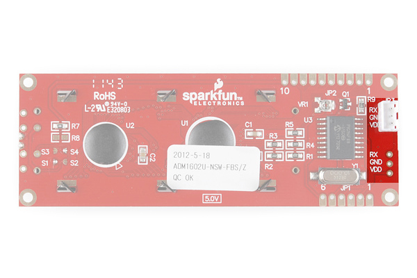 |
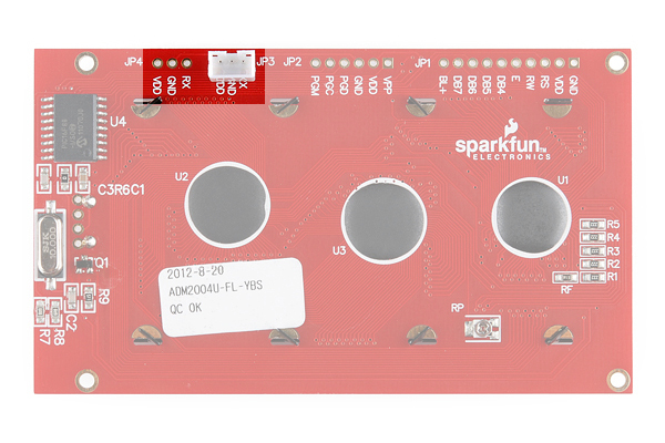 |
| Input for Serial Enabled LCD 16x2 | Input for Serial Enabled LCD 20x4 |
Hookup Table
There are only three connections you need to make to the LCD. Check your LCD's pinout before connecting to your Arduino. If you look closely at the LCD's with the JST connector, the input voltage (VDD) and Rx are in different locations on the board depending on how it was populated.
| Serial Enabled LCD Pinout | Arduino Pin | Description |
|---|---|---|
| RX | D11 | Serial UART receive input to the display. 9600 baud (default), 8 bits, 1 stop, no parity. |
| GND | GND | Ground for the power supply. |
| VDD | 3.3V or 5V | Power supply, this should be either +3.3V or +5V depending on the specs of your LCD. |

Firmware Overview
Baud Rate
Set the serial interface to: 9600 baud, 8 bits of data, 1 start bit, 1 stop bit, and no parity (9600,8,1,1,N). This can be changed or updated using the following command set. However, be aware that if you change the communication protocol, you may not be able to re-connect or control the device until your microcontroller's baud rate matches.
Data & Display Information
All settings are stored on onboard EEPROM and loaded during power up. To display data on the SerLCD and built-in serial enabled LCDs, you simply send ASCII-formatted characters using a serial interface which matches the communication protocol. This means that if you pass the ASCII character 'r' to the module, an 'r' will be displayed on the LCD at the next cursor position.
Configuration & Command Set
There are two reserved control characters used to control and configure various features on the LCD. The control characters are 0xFE and 0x7C. Sending a control character followed by a command will allow you to control the cursor, backlight, and other features on the SerialLCD. A complete table of commands are shown below in hexadecimal and decimal value in brackets. Either representation is acceptable when sending a control or command character. The HD44780 LCD controller is very common. The extended commands for this chip include but are not limited to those described in table. Please refer to the HD44780 datasheet for more information.
| Control Character | Command Character | Description |
|---|---|---|
| 0xFE [ 0d254 ] | 0x01 [ 0d1 ] | Clear Display |
| 0x14 [ 0d20 ] | Move Cursor Right 1 Space | |
| 0x10 [ 0d16 ] | Move Cursor Left 1 Space | |
| 0x1C [ 0d28 ] | Scroll Right 1 Space | |
| 0x18 [ 0d24 ] | Scroll Left 1 Space | |
| 0x0C [ 0d12 ] | Turn Display On / Hide Cursor | |
| 0x08 [ 0d8 ] | Turn Display Off | |
| 0x0E [ 0d14 ] | Underline Cursor On | |
| 0x0D [ 0d13 ] | Blinking Cursor On | |
| 0x80 + n [ 0d128 + p ] | Set Cursor Position, where n is the hexadecimal position and p is the decimal value of the position |
|
| 0x7C [ 0d124 ] | 0x03 [ 0d3 ] | 20 Characters Wide |
| 0x04 [ 0d4 ] | 16 Characters Wide | |
| 0x05 [ 0d5 ] | 4 Lines | |
| 0x06 [ 0d6 ] | 2 Lines | |
| 0x09 [ 0d9 ] | Turn Splash Screen On/Off | |
| 0x0A [ 0d10 ] | Set Splash Screen | |
| 0x0B [ 0d11 ] | Set to 2400 Baud | |
| 0x0C [ 0d12 ] | Set 4800 Baud | |
| 0x0D [ 0d13 ] | Set 9600 Baud (Default) | |
| 0x0E [ 0d14 ] | Set 14400 Baud | |
| 0x0F [ 0d15 ] | Set 19200 Baud | |
| 0x10 [ 0d16 ] | Set 38400 Baud | |
| 0x80 [ 0d128 ] | Backlight Off | |
| 0x9D [ 0d157 ] | Backlight Full On | |
| 0x12 [ 0d18 ] | Reset to Default Baud While LCD's Splash Screen is Still Active |
Clear Screen and Set Cursor Position
Clear display and set cursor position are the two commands that are used frequently. To clear the screen, send the control character 0xFE followed by 0x01. Clearing the screen resets the cursor position back to position 0 (i.e. the first character on the first line).
To set the active cursor position, send the control character 0xFE followed by 0x80 + n, where n is an offset in hexadecimal as described in the tables below. In this case, it would be easier to use the decimal value for setting the cursor position (0d128) with the viewable cursor position (p) and then send the value.
| 16 Character Displays | |
|---|---|
| Line Number | Viewable Cursor Positions (Decimal) |
| 1 | 0-15 |
| 2 | 64-79 |
| 3 | 16-31 |
| 4 | 80-95 |
| 20 Character Displays | |
|---|---|
| Line Number | Viewable Cursor Positions (Decimal) |
| 1 | 0-19 |
| 2 | 64-83 |
| 3 | 20-39 |
| 4 | 80-103 |
Example of Setting the Cursor Position
Say we want to the place a character on the third character position of the second line in a 16x2 character display. The cursor position is not what you would expect. Notice that the last character on line 2 jumps from 15 to 64 on the next line? To do this we need to:
- Add 0x80 to the viewable cursor position as stated earlier. Since we are trying to add a hexadecimal value with a decimal, you would need to convert a value to the same representation. Since we know that 0x80 is also 0d128, we will just stick with decimal. Therefore, the third character on the second line in decimal is: 128 + 66 = 194.
- Now that we know the position, send the command character 0xFE to tell the SerLCD you want to send a command followed by the number 194. If you are comfortable converting back to hexadecimal, you can also send 0xC2.
- The cursor should now be sitting in the third position of the second line. Sending any other character will display on the LCD starting at this position.
Setting Up the LCD Size
The SerLCD backpack's firmware includes settings to interface for the following types of LCDs:
- 16x2
- 16x4
- 20x2
- 20x4
If you purchased the SerLCD backpack module by itself, you will have to configure the module to the type of LCD it is going to be, or is currently attached. To set the type of LCD the SerLCD module is attached to, transmit the control character 0x7C followed with either 0x03, 0x04, 0x05, or 0x06 as explained in the SerLCD Command Set above. These commands set the LCD character width and number of lines. These settings are used to correctly wrap the cursor to keep it within the viewable screen. The type of LCD is saved to EEPROM after each change.
If you purchased the built-in serial enabled LCD, it has already been configured to work with that specific LCD. You should not have to configure anything.
Changing the Baud Rate
The backpack and built-in serial enabled LCD defaults to 9600 baud, but they can be set to a variety of baud rates.
If the serial enabled LCD gets into an unknown state or you otherwise can't communicate with it, try sending a "CTRL-R" (0x12) character at 9600 baud while the splash screen is active (during the first 500 ms of boot-up) and the unit will reset to 9600 baud.
Backlight Brightness
The SerLCD v2.5 provides you with control of the backlight to one of 30 different brightness levels. To control the backlight, send the control character 0x7C followed by a number from 0x80 to 0x9D. Sending a 0x80 sets the backlight to off and 0x9D sets the backlight to fully on.
This is handy when power consumption of the unit must be minimized. By reducing the brightness, the overall backlight current consumption is reduced.
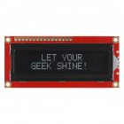
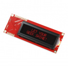
Splash Screen
The SerLCD and built-in serial enabled LCD displays a splash screen by default. This splash screen verifies that the unit is powered, working correctly, and that the connection to the LCD is correct. The splash screen is displayed for 500 ms during boot-up and may be turned off if desired.

Setting Splash Screen
A new addition to the V2.5 firmware is the ability for the user to set their own splash screen (2 lines). To do this, just set the top 2 lines as you would like them to appear, send the control character 0x7C followed by "CTRL-J" (0x09) to save it to memory. To test, just cycle power.
Turning Splash Screen On/Off
To disable the splash screen, send the control character 0x7C to the unit followed by "CTRL-J" (0x0A). Every time this command is sent to the unit, the splash screen display option will toggle. If the splash screen is currently being displayed, sending the 0x7C and 0x0A characters will disable the splash screen during the next boot, and sending the 0x7C and 0x0A characters again will enable the splash screen.
Extended Command
When testing the extended LCD command 0x0C, the command used all three of the following commands:
- Turn Visual Display On
- Underline Cursor Off
- Blinking Box Cursor Off
So if you had the cursor/blinking box on and turned the visual display off, the cursor/blinking box would not remain on after after issuing the 0xFE control and 0x0C command value to turn the screen back on.
Example Code
Note: This example assumes you are using the latest version of the Arduino IDE on your desktop. If this is your first time using Arduino, please review our tutorial on installing the Arduino IDE. If you have not previously installed an Arduino library, please check out our installation guide.
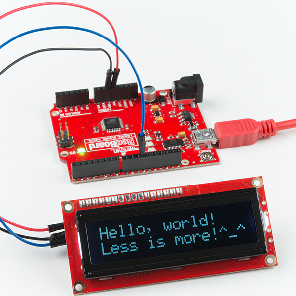
For simplicity, we will be using an Arduino microcontroller. In this example, we connected a serial enabled LCD to the RedBoard programmed with Arduino (basically an Arduino Uno with an ATmega328P).
Example 1: Hello World!
Copy and paste these sketch into your Arduino IDE.
language:c
// SparkFun Serial LCD example 1
// Clear the display and say "Hello World!"
// This sketch is for Arduino versions 1.0 and later
// If you're using an Arduino version older than 1.0, use
// the other example code available on the tutorial page.
// Use the Software Serial library to create a new "soft" serial port
// for the display. This prevents display corruption when uploading code.
#include <SoftwareSerial.h>
// Attach the serial enabld LCD's RX line to digital pin 11
SoftwareSerial LCD(10, 11); // Arduino SS_RX = pin 10 (unused), Arduino SS_TX = pin 11
void setup()
{
LCD.begin(9600); // set up serial port for 9600 baud
delay(500); // wait for display to boot up
}
void loop()
{
// move cursor to beginning of first line
LCD.write(254);
LCD.write(128);
// clear display by sending spaces
LCD.write(" ");
LCD.write(" ");
// move cursor to beginning of first line
LCD.write(254);
LCD.write(128);
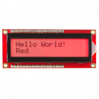
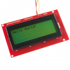
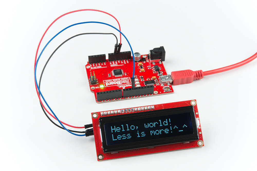
LCD.write("Hello, world!");
// move cursor to beginning of second line
LCD.write(254);
LCD.write(192);
LCD.write("Less is more!^_^");
while(1); // wait forever
}
When you power up the board, you'll briefly see a SparkFun splash screen, and then the display will go blank. To send text to the board, wait 1/2 second (500ms) after power up for the splash screen to clear, then send text to the display through your serial port. The display understands all of the standard ASCII characters (upper and lowercase text, numbers, and punctuation), plus a number of graphic symbols and Japanese characters. See the HD44780 datasheet for the full list of supported characters.
If you send data that goes past the end of the first line, it will skip to the start of the second line. If you go past the end of the second line, the display will jump back up to the beginning of the first line.
Here's what you should see after uploading the code to your Arduino. Try changing the text with a different message!
Example 2: Move the Cursor
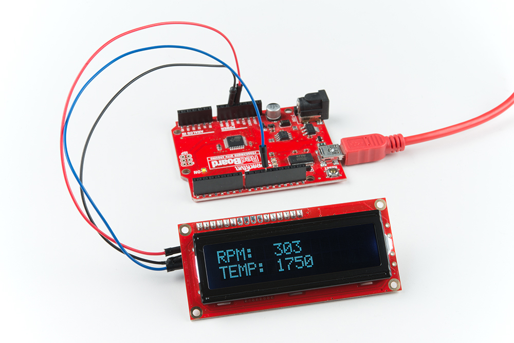
A common LCD technique is to repeatedly display changing numbers such as RPM or temperature in the same place on the display. You can easily do this by moving the cursor before sending your data.
To move the cursor, send the special character (0xFE), followed by the cursor position you'd like to set. Each cursor position is represented by a number, see the table below to determine the number in decimal to send for a serial enabled LCD set to 16x2:
| Position | 1 | 2 | 3 | 4 | 5 | 6 | 7 | 8 | 9 | 10 | 11 | 12 | 13 | 14 | 15 | 16 |
|---|---|---|---|---|---|---|---|---|---|---|---|---|---|---|---|---|
| Line 1 | 128 | 129 | 130 | 131 | 132 | 133 | 134 | 135 | 136 | 137 | 138 | 139 | 140 | 141 | 142 | 143 |
| Line 2 | 192 | 193 | 194 | 195 | 196 | 197 | 198 | 199 | 200 | 201 | 202 | 203 | 204 | 205 | 206 | 207 |
For example, if you want to move to the beginning of the second line, send the control character 0xFE and command character 0d192.
Here's a slightly more complex example showing how to display data at fixed points on the display, plus the use of sprintf() to convert numbers to strings (this right-justifies the numbers with leading spaces, which keeps them from "jumping around" if the number of digits changes):
language:c
// SparkFun Serial LCD example 2
// Format and display fake RPM and temperature data

// This sketch is for Arduino versions 1.0 and later
// If you're using an Arduino version older than 1.0, use
// the other example code available on the tutorial page.

// Use the Software Serial library to create a new "soft" serial port
// for the display. This prevents display corruption when uploading code.
#include <SoftwareSerial.h>

// Attach the serial enabld LCD's RX line to digital pin 11
SoftwareSerial LCD(10, 11); // Arduino SS_RX = pin 10 (unused), Arduino SS_TX = pin 11

void setup()
{
  LCD.begin(9600); // set up serial port for 9600 baud
  delay(500); // wait for display to boot up

  // cursor to beginning of first line
  LCD.write(254);
  LCD.write(128);

  // clear display + legends
  LCD.write("RPM:            ");
  LCD.write("TEMP:           ");
}

int temp, rpm;
char tempstring[10], rpmstring[10]; // create string arrays

void loop()
{
  temp = random(1000); // make some fake data
  rpm = random(10000);

  sprintf(tempstring,"%4d",rpm); // create strings from the numbers
  sprintf(rpmstring,"%4d",temp); // right-justify to 4 spaces

  LCD.write(254); // cursor to 7th position on first line
  LCD.write(134);

  LCD.write(rpmstring); // write out the RPM value

  LCD.write(254); // cursor to 7th position on second line
  LCD.write(198);

  LCD.write(tempstring); // write out the TEMP value

  delay(1000); // short delay
}
You should see something similar to the image below. Try reading a sensor and displaying the values on the screen!
SerLCD Demo
This is an extensive example sketch that shows you how to create a scrolling marquee, create a timer, display sensor data, and control the backlight. Copy and paste the following example to the Arduino IDE. Upload the example to your Arduino to test!
language:c
/***********************************************************************
  SerLCD Demo Example Code
  Written by: Joel Bartlett @ SparkFun Electronics
  Date: December 20, 2012
  Modified by: Ho Yun "Bobby" Chan @ SparkFun Electronics
  Date: May 3, 2018

  This code uses the information presented in the SerLCD Datasheet
  to create an Arduino example using the SerLCD from SparkFun Electonics.
  Each of the SerLCD's capabilities is broken up into seperate functions
  within the sketch. Simply call each function with the correct parameters
  to get the desired result form the LCD screen.

  This code was developed for the Arduino IDE v102

  To use, connect the following pins
      VDD -> 5V
      GND -> GND
      LCD RX -> Arduino TX (pin 11)

    ***Don't forget to disconnect the LCD's RX pin from the TX pin of
the Arduino's UART line while programming!***

  You can also check out the SerLCD library from Arduino
http://playground.arduino.cc/Code/SerLCD

  If you need to reprogram often, or need the UART for another device,
  you can use the Software Serial libary to create a
  seperate UART for the LCD.
  Arduino IDE -> Sketch -> Import Library ->Software Serial

  To declare a new UART using SoftwareSerial, insert this line:
  SoftwareSerial NAME(x,y); // RX, TX
  where Name is the name of the new UART, x is the RX pin, and y is the TX     pin.

  "THE BEER-WARE LICENSE"
  As long as you retain this notice you can do whatever you want with this stuff.
  If we meet some day, and you think this stuff is worth it, you can buy me a beer.
************************************************************************/
#include <SoftwareSerial.h>

SoftwareSerial LCD(10, 11); // Arduino SS_RX = pin 10 (unused), Arduino SS_TX = pin 11

//-------------------------------------------------------------------------------------------
void setup()
{
LCD.begin(9600);// all SerLCDs come at 9600 Baud by default
}
//-------------------------------------------------------------------------------------------
void loop()
{
  scrollingMarquee();
  tempAndHumidity();
  counter();
  backlight();
  cursors();
}
//-------------------------------------------------------------------------------------------
void clearScreen()
{
  //clears the screen, you will use this a lot!
  LCD.write(0xFE);
  LCD.write(0x01);
}
//-------------------------------------------------------------------------------------------
void selectLineOne()
{
  //puts the cursor at line 0 char 0.
  LCD.write(0xFE); //command flag
  LCD.write(128); //position
}
//-------------------------------------------------------------------------------------------
void selectLineTwo()
{
  //puts the cursor at line 0 char 0.
  LCD.write(0xFE); //command flag
  LCD.write(192); //position
}
//-------------------------------------------------------------------------------------------
void moveCursorRightOne()
{
  //moves the cursor right one space
  LCD.write(0xFE); //command flag
  LCD.write(20); // 0x14
}
//-------------------------------------------------------------------------------------------
void moveCursorLeftOne()
{
  //moves the cursor left one space
  LCD.write(0xFE); //command flag
  LCD.write(16); // 0x10
}
//-------------------------------------------------------------------------------------------
void scrollRight()
{
  //same as moveCursorRightOne
  LCD.write(0xFE); //command flag
  LCD.write(20); // 0x14
}
//-------------------------------------------------------------------------------------------
void scrollLeft()
{
  //same as moveCursorLeftOne
  LCD.write(0xFE); //command flag
  LCD.write(24); // 0x18
}
//-------------------------------------------------------------------------------------------
void turnDisplayOff()
{
  //this tunrs the display off, but leaves the backlight on.
  LCD.write(0xFE); //command flag
  LCD.write(8); // 0x08
}
//-------------------------------------------------------------------------------------------
void turnDisplayOn()
{
  //this turns the dispaly back ON
  LCD.write(0xFE); //command flag
  LCD.write(12); // 0x0C
}
//-------------------------------------------------------------------------------------------
void underlineCursorOn()
{
  //turns the underline cursor on
  LCD.write(0xFE); //command flag
  LCD.write(14); // 0x0E
}
//-------------------------------------------------------------------------------------------
void underlineCursorOff()
{
  //turns the underline cursor off
  LCD.write(0xFE); //command flag
  LCD.write(12); // 0x0C
}
//-------------------------------------------------------------------------------------------
void boxCursorOn()
{
  //this turns the box cursor on
  LCD.write(0xFE); //command flag
  LCD.write(13); // 0x0D
}
//-------------------------------------------------------------------------------------------
void boxCursorOff()
{
  //this turns the box cursor off
  LCD.write(0xFE); //command flag
  LCD.write(12); // 0x0C
}
//-------------------------------------------------------------------------------------------
void toggleSplash()
{
  //this toggles the splash screen
  //if off send this to turn on
  //if on send this to turn off
  LCD.write(0x7C); //command flag = 124 dec
  LCD.write(9); // 0x09
}
//-------------------------------------------------------------------------------------------
int backlight(int brightness)// 128 = OFF, 157 = Fully ON, everything in between = varied
{
  //this function takes an int between 128-157 and turns the backlight on accordingly
  LCD.write(0x7C); //NOTE THE DIFFERENT COMMAND FLAG = 124 dec
  LCD.write(brightness); // any value between 128 and 157 or 0x80 and 0x9D
}
//-------------------------------------------------------------------------------------------
void scrollingMarquee()
{
//This function scroll text across the screen on both lines
  clearScreen(); // it's always good to clear the screen before moving onto a new print
  for(int j = 0; j < 17; j++)
  {
    selectLineOne();
    for(int i = 0; i < j;i++)
      moveCursorRightOne();
    LCD.print("SPARK");
    selectLineTwo();
    for(int i = 0; i < j;i++)
      moveCursorRightOne();
    LCD.print(" FUN");
    delay(500); // you must have a delay, otherwise the screen will print and clear before you can see the text
    clearScreen();
  }
}
//-------------------------------------------------------------------------------------------
void counter()
{
  //this function prints a simple counter that counts to 10
  clearScreen();
  for(int i = 0; i <= 10; i++)
  {
    LCD.print("Counter = ");
    LCD.print(i, DEC);
    delay(500);
        clearScreen();
  }
}
//-------------------------------------------------------------------------------------------
void tempAndHumidity()
{
  //this function shows how you could read the data from a temperature and humidity
  //sensor and then print that data to the SerLCD.

  //these could be varaibles instead of static numbers
  float tempF = 77.0;
  float tempC = 25.0;
  float humidity = 67.0;

  clearScreen();
  selectLineOne();
  LCD.print(" Temp = ");
  LCD.print((long)tempF, DEC);
  LCD.print("F ");
  LCD.print((long)tempC, DEC);
  LCD.print("C");
  selectLineTwo();
  LCD.print(" Humidity = ");
  LCD.print((long)humidity, DEC);
  LCD.print("%");
  delay(2500);
}
//-------------------------------------------------------------------------------------------
void backlight()
{
  //this function shows the different brightnesses to the backlight can be set
      clearScreen();
  for(int i = 128; i < 158; i+=2)// 128-157 are the levels from off to full brightness
  {
    backlight(i);
    delay(100);
    LCD.print("Backlight = ");
    LCD.print(i, DEC);
    delay(500);
    clearScreen();
  }
}
//-------------------------------------------------------------------------------------------
void cursors()
{
  //this function shows the different cursors avaiable on the SerLCD
  clearScreen();

  boxCursorOn();
  LCD.print("Box On");
  delay(1500);
  clearScreen();

  boxCursorOff();
  LCD.print("Box Off");
  delay(1000);
  clearScreen();

  underlineCursorOn();
  LCD.print("Underline On");
  delay(1500);
  clearScreen();

  underlineCursorOff();
  LCD.print("Underline Off");
  delay(1000);
  clearScreen();
}
Alternative Libraries
Alternatively, you can use the SerLCD library found on the Arduino.cc website.
If you are using Linux, you may want to try this library instead.
Troubleshooting
Random Character
If the display is powered up without the RX line connected to anything, the display may fill with strange characters. This is because the display is receiving random noise on the disconnected line. If you connect the RX line to a true TX port, this will not happen.
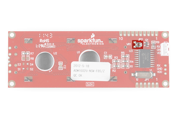
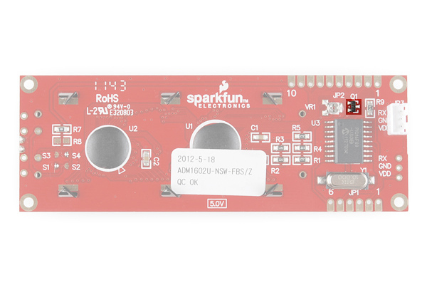
Faded Characters on Display
If the display is unreadable or washed out, the contrast may need to be adjusted. Send some text to the display (see the first example sketch above), then use a miniature Phillips screwdriver to gently turn the contrast trimpot labeled VR1 on the back of the display until the text is as clear as possible (please be gentle with the trimpot). This display also has a backlight that can be adjusted for best readability, see the LCD datasheet for information.
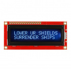
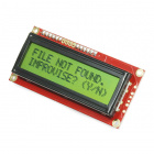
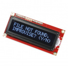
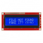
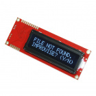
Bricked LCD
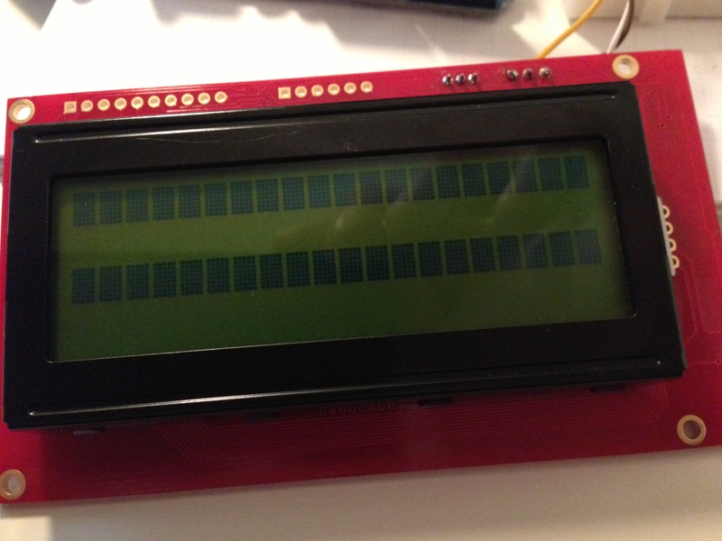
If you are seeing two rows of ASCII blocks (i.e. █ ) or random characters, it's possible that you might have bricked the serial enabled LCD by putting it into an unknown state. This is a common problem if you are uploading code to the Arduino while another device is connected to the same hardware UART line (i.e. pin 0 and 1). Some systems like Arduino send bootloader information out the serial port when the system starts up. This will cause the LCD to output random characters usually on the screen or not even show anything on the screen. If this is a problem, make sure to use a software defined serial pin to create a TX pin that doesn't get used during startup.
 |
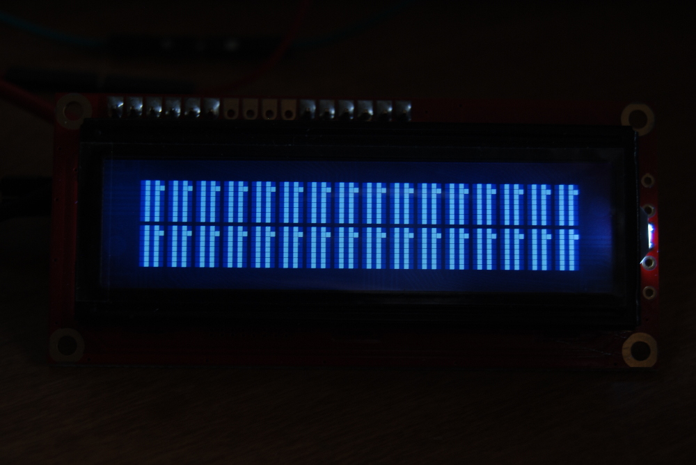 |
| Bricked Serial Enabled LCD 20x4 | Bricked Serial Enabled LCD 16x2 |
Recovering from Unknown State: Software Reset
If the Serial LCD gets into an unknown state and you are not able to communicate with it anymore, just write 0x12 in the loop so that it is constantly sending the hex value to the screen when the LCD's splash screen is active (or when the LCD is powered) to reset the unit back to 9600 baud as explained earlier. The screen will temporarily revert to 9600 baud until power is cycled. This is to allow you to regain control of the display if you set it to an unknown baud rate. Make sure to also change the baud rate in the EEPROM.
The old datasheet in section 3.4 indicates that you need to send a command character 0x7C in hexadecimal. If you look at the ASCII table for the non-printing control characters (CTRL-K through CTRL-P), there are hex values for the different baud rates that you would need to send to the LCD.
| Non-Printing Control Characters | Command Character | Description |
|---|---|---|
| <control>K | 0x0B [ 0d11 ] | Set to 2400 Baud |
| <control>L | 0x0C [ 0d12 ] | Set 4800 Baud |
| <control>M | 0x0D [ 0d13 ] | Set 9600 Baud (Default) |
| <control>N | 0x0E [ 0d14 ] | Set 14400 Baud |
| <control>O | 0x0F [ 0d15 ] | Set 19200 Baud |
| <control>P | 0x10 [ 0d16 ] | Set 38400 Baud |
| <control>R | 0x12 [ 0d18 ] | Reset to Default Baud While LCD's Splash Screen is Still Active |
All you have to do is create a new void function similar to the one below and call it when you are running the Arduino sketch file like this:
language:c
void changeBaud(){
  LCD.write(0x7C);// special command byte
  LCD.write(0x0D); //change current baud to 9600 baud
}
Here's some code with Arduino to try and unbrick the PIC16F88 on the serial enabled LCDs. This sometimes works and there is a higher probability of recovering your LCD if you still are able to see the splash screen.
Recovering from Unknown State: PICkit Programmer
The last resort is to use the PICkit 3 programmer and reupload the firmware on the LCD using MPLAB. If you are trying to recover a bricked serLCD backpack, you will need a few of the following materials listed below to connect to the programming header. The built-in serial enabled LCD will have standard 0.1" spaced headers so the IC hooks will not be necessary as long as there is contact with the pins during programming.

MPLAB PICkit 3
PGM-09973Using MPLAB X IDE v2.30
For this example, we will be using MPLAB X IDE V2.30 for Windows. Head over to MicroChip's archived downloads to download and install.
Also, make sure to download the hex file specific for your LCD to recover. We will be using the .hex file linked for the serial enabled LCD backpack below. If you are using the ones with the built-in serial, you will need to unzip the folder before using the file.
|
 |
 |
| Download serlcd-v2_6_2line_10MHz (HEX) |
Download serlcd-v2_7_2line_10MHz (ZIP) |
Download serlcd-v2_7_4line_10MHz (ZIP) |
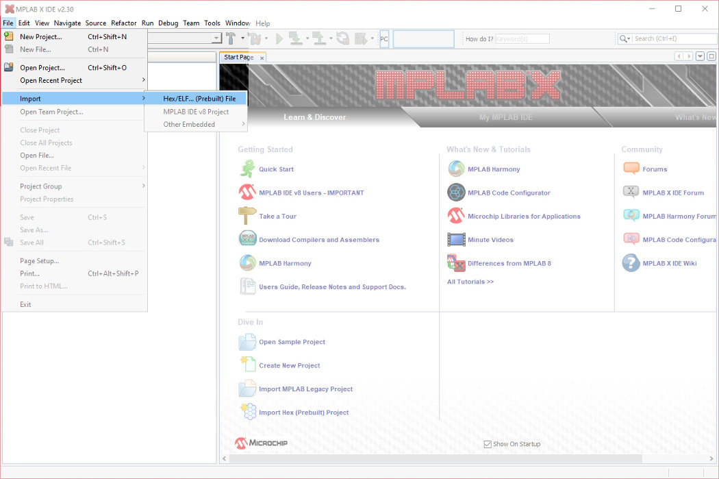
Once installed, select File > Import > Hex/ELF... (Prebuilt) File.
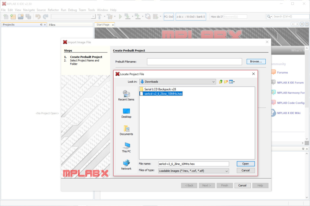
Click on the Browse... button and head to the location where the .hex file is stored on your computer. This will probably be in your recent downloads. Select the file and click on the Open button. This will automatically provide the path for the Prebuilt Filename which is .../serlcd-v2_6_2line_10MHz.hex.
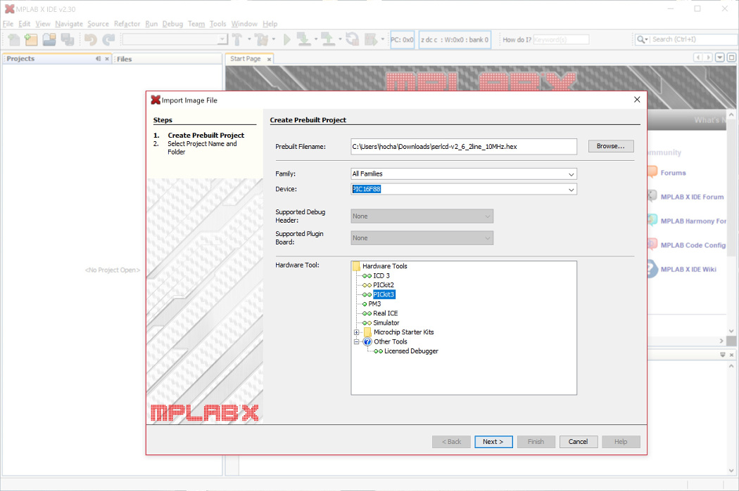
Then type in the Device field: PIC16F88. If you have a PIC16LF88 that is populated on the SerLCD backpack, this is the same device that you would select. The programmer will not notice a difference between the two PICs. Once selected, click on the Next > button.
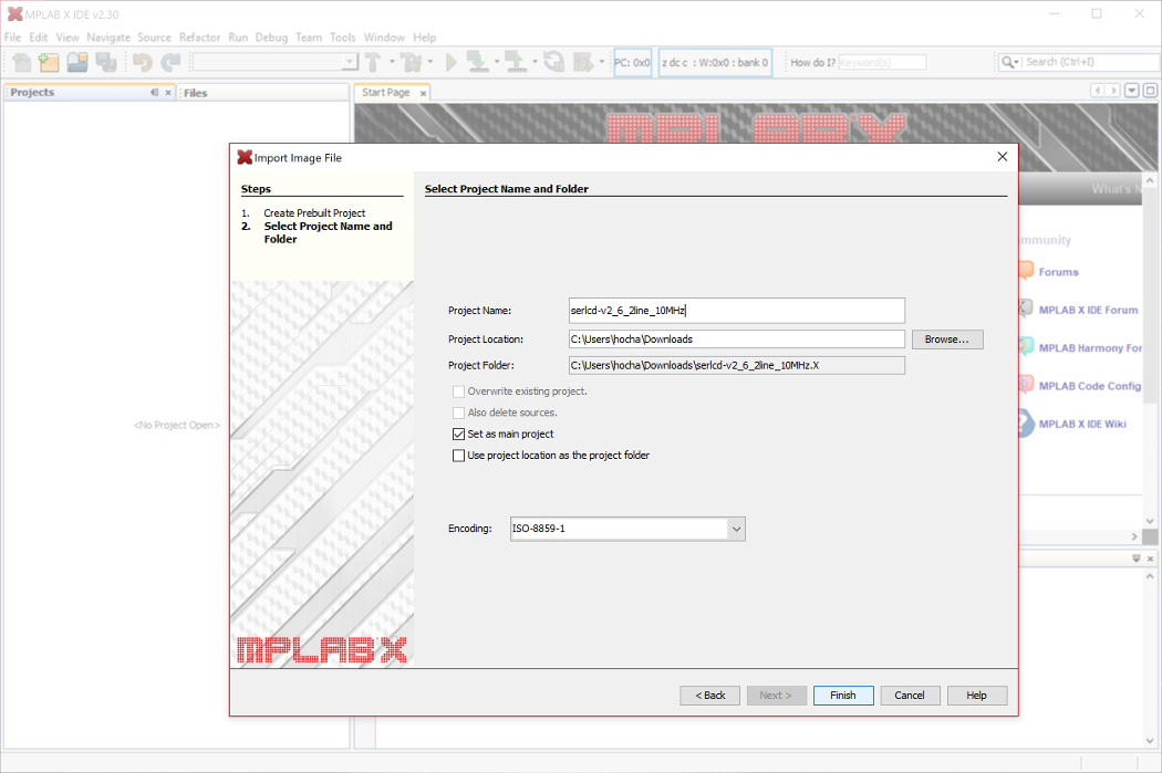
Click Finish to save as a project.
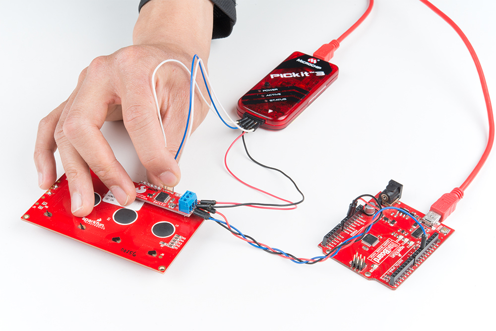
Connect the PICkit 3 to your computer using the USB cable. At this point, make the connection from the PICkit 3 to the programming pins of the LCD. Power the target (your PIC16LF88) from a separate power supply like an Arduino using wires. The PICkit 3 may not have enough power to power the target.
If you are using a 3.3V LCD, make sure to read the note highlighted in red below.
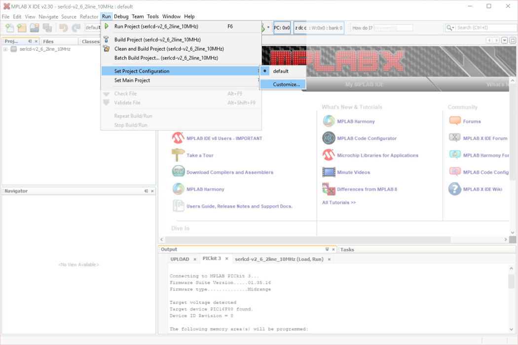
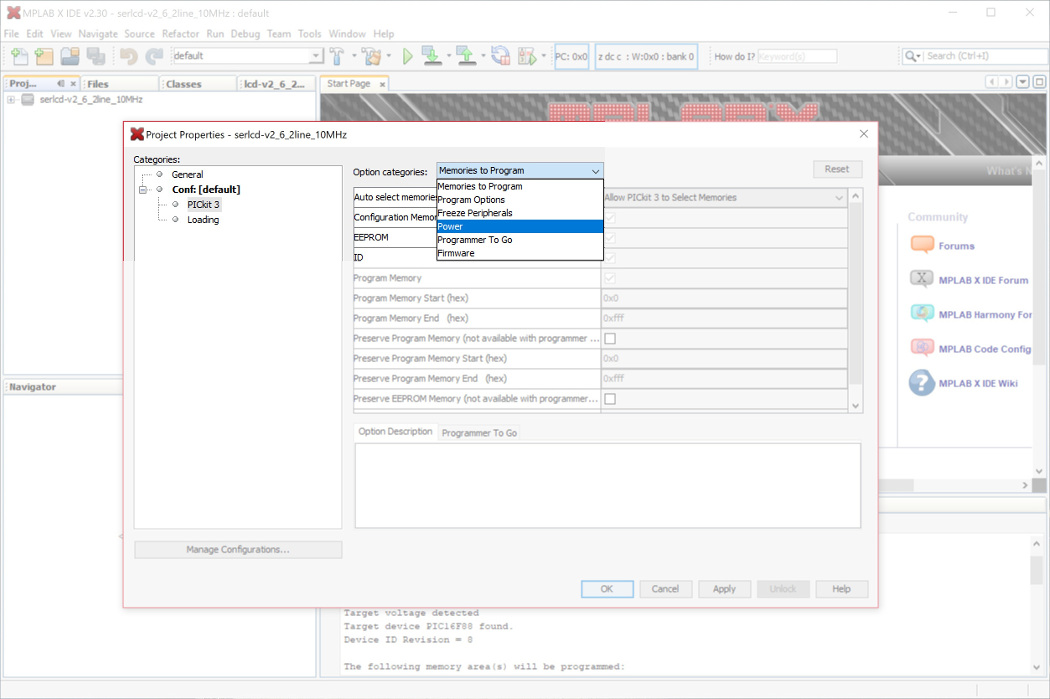
From the Categories: tree, select the PICkit 3 programmer. Under the Option categories: drop down menu, select Power.
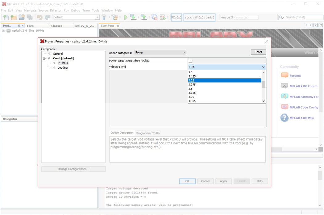
Under Voltage Level, select 3.25. This should be a sufficient enough for flashing the PIC. Click OK button to save.
The PICkit 3 programmer's pinout is listed on page 15 of PICkit 3 user manual. To connect, start by connecting the LCD's programming header indicated by the polarity marker and move toward the other side.
| PICkit 3 Programmer Connector Pinout | Notes |
|---|---|
| VPP | Indicated by an Arrow, connect to pin "1" or a straight bar " ¯ " |
| VDD Target | 3.3V or 5V depending on your LCD |
| VSS (GND) | Ground |
| PGD | Data |
| PGC | Clock |
| LVP | Not Connected on SerLCD backpack |
If you are using a 5V LCD, you can connect to the backpack with jumper wires (specifically wires with small pins) like the images shown below. When reflashing, the target voltage and GND pins were connected to the screw terminal. The PIC16LF88 can be reflashed as long as the pins are held in place during programming. Make sure the pins are not touching the LCD underneath.
 |
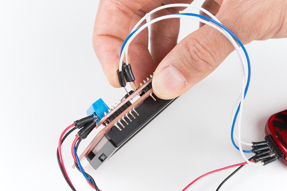 |
| Jumper Wires Between PICkit3 and SerLCD Backpack | Make Sure the Pins are Not Touching the LCD Underneath |
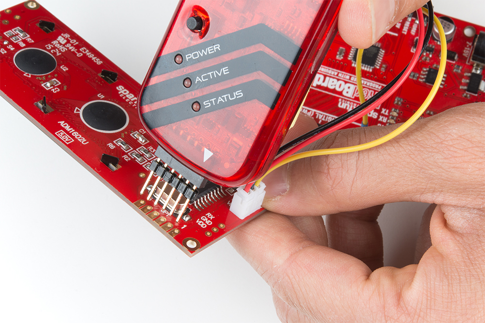
For those with the built-in serial enabled LCD programming pins, you could just connect using header pins by aligning the arrow to the pin "1".
Then click on the icon's drop down menu that looks like the software is downloading to a PIC chip (i.e. the button next to the Run Project button) and select Make and Program Device Programmer to Go PICkit3 (Project serlcd-v2_6_2line_10MHz).
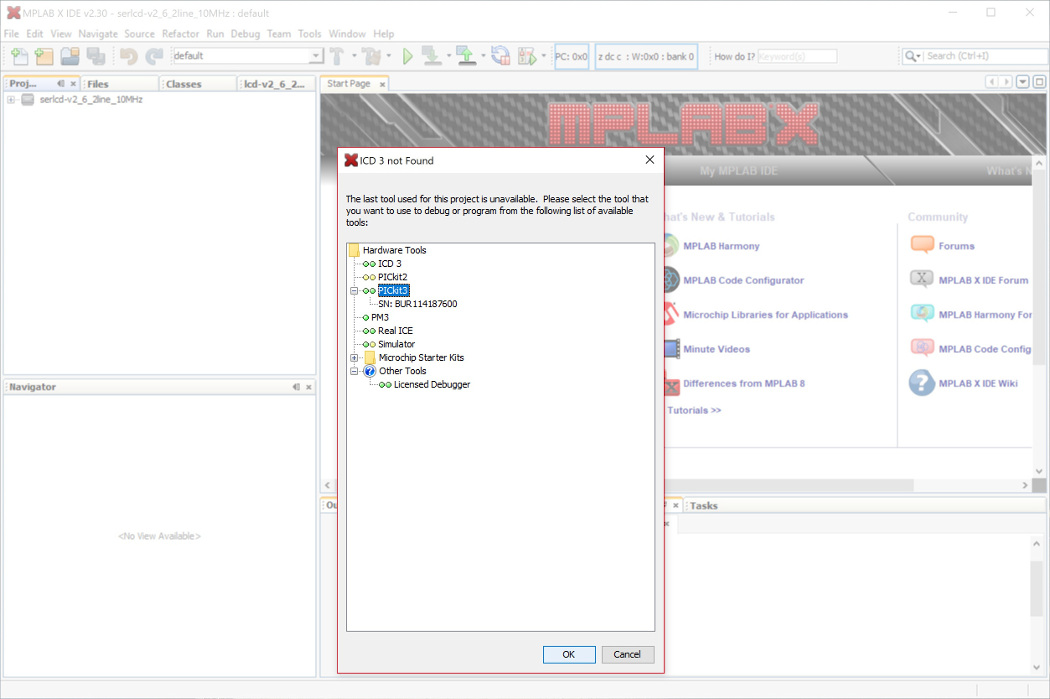
A message will pop up if you did not select the correct programmer.
Select PICkit 3 in the tree and click the OK button.
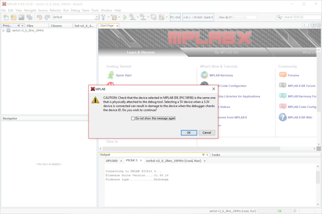
The software will pop up with this message:
If you followed the steps earlier to configure the PICkit 3 for a 3.3V LCD or are using a 5V LCD, click OK.
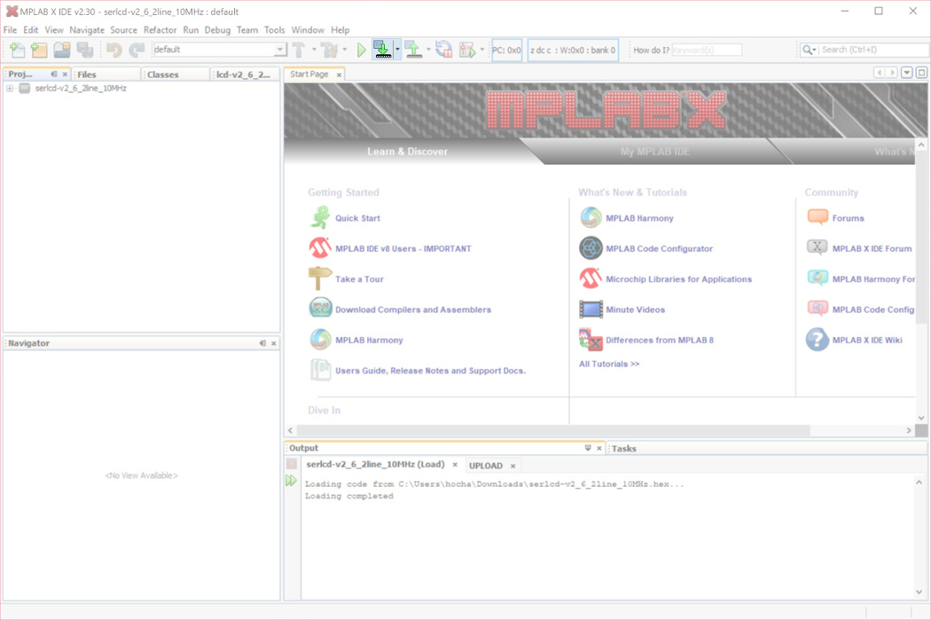
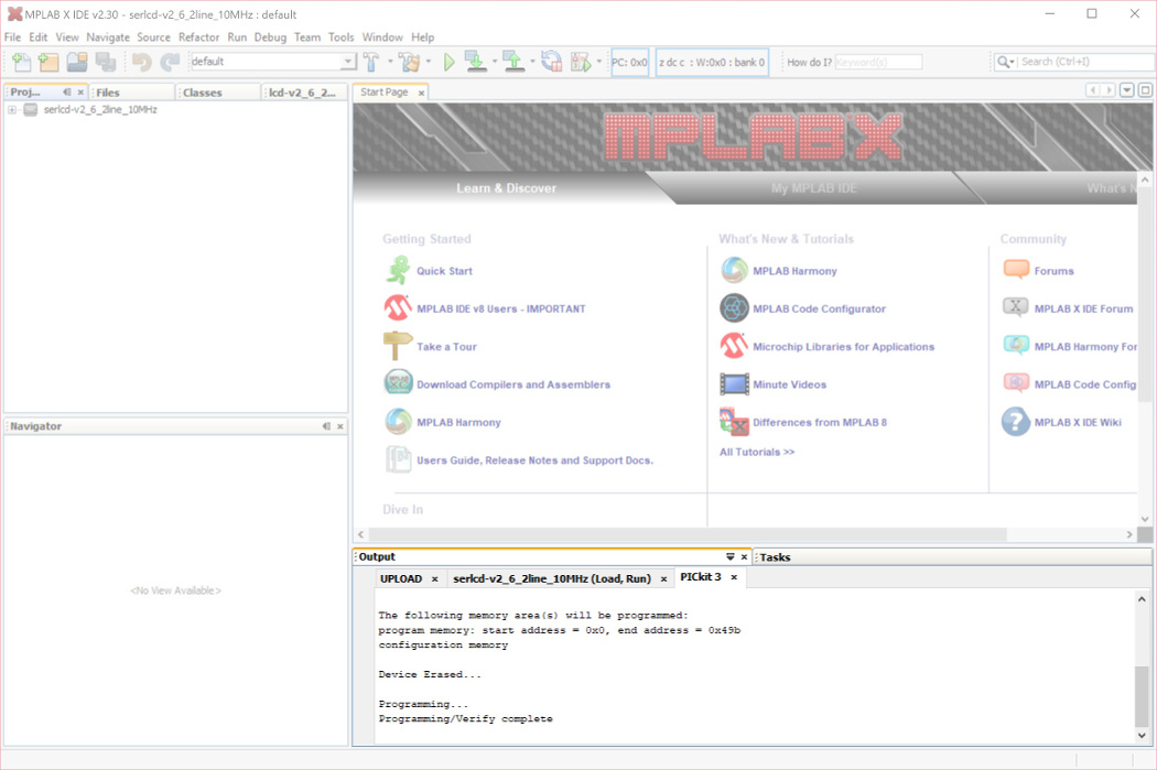
From there, the hex file should begin flashing on the chip and the program will run immediately after displaying this output:
language:c
*****************************************************

Connecting to MPLAB PICkit 3...
Firmware Suite Version.....01.28.90 *
Firmware type..............Midrange

Target voltage detected
Target device PIC16F88 found.
Device ID Revision = 8

The following memory area(s) will be programmed:
program memory: start address = 0x0, end address = 0x4ab
configuration memory

Device Erased...

Programming...
Programming/Verify complete
You should see this output at the bottom of the MPLAB X IDE.
Power cycle the screen. Congrats! We have recovered the LCD! Or, at least for a 16x2 character LCD... The firmware we flashed was set for the 16 characters and 2 lines. The next step is to configure the PIC for a 20x4 character LCD. To do this, we just need to send the control and command flags to adjust the width and lines. Place this your Arduino's setup() function after setting your Arduino's software serial port.
language:c
void set_20x4(){//set character LCD as 20x4
  LCD.write(0x7C); //command flag
  LCD.write(0x03);     //20 char wide
  LCD.write(0x7C); //command flag
  LCD.write(0x05);     //4 lines
  /*NOTE: Make sure to power cycle the serial enabled LCD
  after re-configuring the # char and lines.*/
}
Power cycle the screen and run the demo example to see if everything is working as expected. Ok, now we have recovered your 20x4 serial enabled LCD!
More Examples of Setting Cursor Position
As stated earlier, to set the LCD's cursor position, you would send the command character/flag. Then send additional number related to the cursor's position on the LCD screen. This example goes over how to set the cursor position for a 20x4 serial enabled LCD. Just add 128 to the cursor's position as stated on page 3 of the datasheet to place the cursor at the correct coordinates.
For example, if you are trying to place the cursor at (line 3, position 0), you would send the command character 0xFE and the associated coordinates. Looking at the datasheet, for the 20x4 serial enabled LCD screen, it looks like 128+20 = 148 . Therefore:
language:c
selectLineThree(){
    LCD.write(0xFE); //command flag
    LCD.write(148); //line 3 , position 0
}
As another example, if you are trying to place the cursor at (line 4, position 0), you would send the command character 0xFE and the associated coordinates. Looking at the datasheet, for the 20x4 serial enabled LCD screen, it looks like 128+84= 212. Therefore:
language:c
selectLineFour(){
    LCD.write(0xFE); //command flag
    LCD.write(212); //line 4 , position 0
}
Using the Serial Enabled LCD on an Atmega32U4's Hardware UART
If you are using the serial enabled LCD with an Atmega32U4-based Arduino (like a Pro Micro, Arduino Leonardo, Arduino LilyPad USB etc), you might need to add a small delay in the setup before you can get it working with the hardware UART (pins 0 and 1). Here's an example:
language:c
///test example using ATmega32U4's hardware UART and delay
void setup() {
  delay(2000);//add delay so the ATmega32U4 can have a second before sending serial data to the LCD
  Serial1.begin(9600);//set up the hardware UART baud
}

void loop() {
  Serial1.print("print something");//send something to the serial enabled LCD
  delay(50);
}
Software Serial for Arduino Due
Unfortunately, you are not able to use the serial enabled LCDs with an Arduino Due due the differences in how change interrupts are used for the ARM processor. The software serial library is not included in the Arduino Due's tree:
Try using the other hardware serial UARTs that are not connected to the Arduino Due's programming pins for uploading. Make sure to adjust the code for the hardware serial UARt.
Changing Width and Character Lines
To adjust the default width and character lines, there is some code listed in this example based on the datasheet to configure the serial enabled LCD.
Resources and Going Further
Now that you've successfully got your serial enabled LCD up and running, it's time to incorporate it into your own project!
For more information, check out the resources below:
- Application Note
- Built-In Serial Enabled LCD 16x2
- HD44780
- Datasheet
- LCD User-Defined Graphics - If you would like to create a custom character, you would need to send a command byte before controlling the individual pixels in the character square.
- SparkFun Forums: Custom Characters on the Serial Enabled LCD Backpack
- Arduino Forums: Changing SparkFun Splash
- GitHub Repo - Serial enabled backpack design files, default firmware, and example code.
Need some inspiration for your next project? Check out some of these related tutorials: