AVR-Based Serial Enabled LCDs Hookup Guide
 QCPete
I2C: Hardware Hookup & Example Code - Basic
Qwiic connection
If you are using Qwiic, then you simply need to plug in a qwiic cable from your controller to your SerLCD. It helps to bend/curl your Qwiic cable a bit before inserting it into the right-angle connector on the SerLCD.
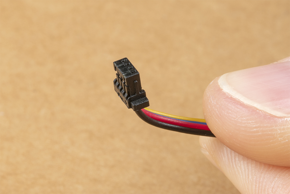
With the bend in place, you can better align it before inserting it all the way.

To avoid stressing the cable wires, it is best to push the Qwiic connector using your fingernails on the sides of the connector plastic. Tweezers can also do the trick.

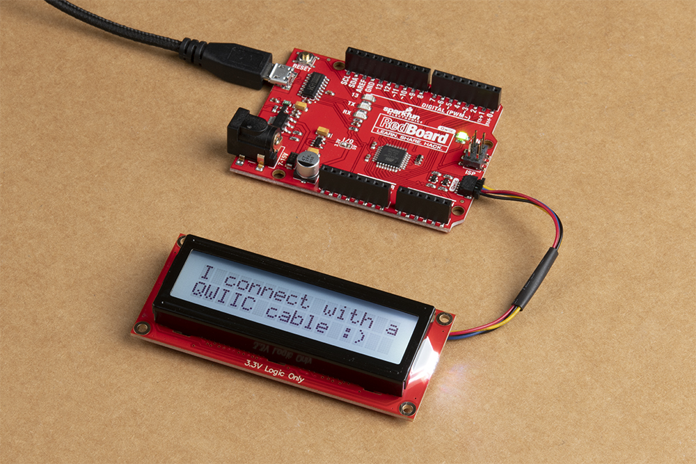
Connect the other end of your Qwiic cable to you controller of choice, and you will be ready to go! Here we are showing the Redboard Qwiic:
Non-Qwiic I2C connection
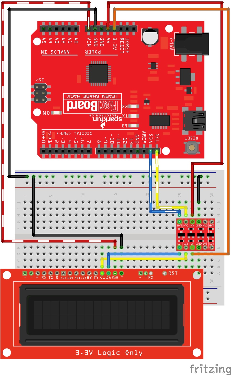
For I2C, there are only 2 communication lines you need to connect: SDA and CLK. But remember, these must be 3.3V logic. So if you are using a 5V Redboard like we are, then you'll need to convert SDA and SCL from 5V to 3.3V. See the following Fritzing diagram for how you can wire this up:
Example Code
After you've got your I2C lines wired up properly (via Qwiic or through logic level converter), you can get the latest example code from the GitHub repo or you can copy and paste the following code into your Arduino IDE:
language:cpp
/*
 OpenLCD is an LCD with Serial/I2C/SPI interfaces.
 By: Nathan Seidle
 SparkFun Electronics
 Date: April 19th, 2015
 License: This code is public domain but you buy me a beer if you use this and we meet someday (Beerware license).
 This is example code that shows how to send data over I2C to the display.
 Note: This code expects the display to be listening at the default I2C address. If your display is not at 0x72, you can
 do a hardware reset. Tie the RX pin to ground and power up OpenLCD. You should see the splash screen
 then "System reset Power cycle me" and the backlight will begin to blink. Now power down OpenLCD and remove
 the RX/GND jumper. OpenLCD is now reset.
 To get this code to work, attached an OpenLCD to an Arduino Uno using the following pins:
 SCL (OpenLCD) to A5 (Arduino)
 SDA to A4
 VIN to 5V
 GND to GND
 Command cheat sheet:
 ASCII / DEC / HEX
 '|'    / 124 / 0x7C - Put into setting mode
 Ctrl+c / 3 / 0x03 - Change width to 20
 Ctrl+d / 4 / 0x04 - Change width to 16
 Ctrl+e / 5 / 0x05 - Change lines to 4
 Ctrl+f / 6 / 0x06 - Change lines to 2
 Ctrl+g / 7 / 0x07 - Change lines to 1
 Ctrl+h / 8 / 0x08 - Software reset of the system
 Ctrl+i / 9 / 0x09 - Enable/disable splash screen
 Ctrl+j / 10 / 0x0A - Save currently displayed text as splash
 Ctrl+k / 11 / 0x0B - Change baud to 2400bps
 Ctrl+l / 12 / 0x0C - Change baud to 4800bps
 Ctrl+m / 13 / 0x0D - Change baud to 9600bps
 Ctrl+n / 14 / 0x0E - Change baud to 14400bps
 Ctrl+o / 15 / 0x0F - Change baud to 19200bps
 Ctrl+p / 16 / 0x10 - Change baud to 38400bps
 Ctrl+q / 17 / 0x11 - Change baud to 57600bps
 Ctrl+r / 18 / 0x12 - Change baud to 115200bps
 Ctrl+s / 19 / 0x13 - Change baud to 230400bps
 Ctrl+t / 20 / 0x14 - Change baud to 460800bps
 Ctrl+u / 21 / 0x15 - Change baud to 921600bps
 Ctrl+v / 22 / 0x16 - Change baud to 1000000bps
 Ctrl+w / 23 / 0x17 - Change baud to 1200bps
 Ctrl+x / 24 / 0x18 - Change the contrast. Follow Ctrl+x with number 0 to 255. 120 is default.
 Ctrl+y / 25 / 0x19 - Change the TWI address. Follow Ctrl+x with number 0 to 255. 114 (0x72) is default.
 Ctrl+z / 26 / 0x1A - Enable/disable ignore RX pin on startup (ignore emergency reset)
 '-'    / 45 / 0x2D - Clear display. Move cursor to home position.
        / 128-157 / 0x80-0x9D - Set the primary backlight brightness. 128 = Off, 157 = 100%.
        / 158-187 / 0x9E-0xBB - Set the green backlight brightness. 158 = Off, 187 = 100%.
        / 188-217 / 0xBC-0xD9 - Set the blue backlight brightness. 188 = Off, 217 = 100%.
 For example, to change the baud rate to 115200 send 124 followed by 18.
*/

#include <Wire.h>

#define DISPLAY_ADDRESS1 0x72 //This is the default address of the OpenLCD

int cycles = 0;

void setup()
{
  Wire.begin(); //Join the bus as master

  //By default .begin() will set I2C SCL to Standard Speed mode of 100kHz
  //Wire.setClock(400000); //Optional - set I2C SCL to High Speed Mode of 400kHz

  Serial.begin(9600); //Start serial communication at 9600 for debug statements
  Serial.println("OpenLCD Example Code");

  //Send the reset command to the display - this forces the cursor to return to the beginning of the display
  Wire.beginTransmission(DISPLAY_ADDRESS1);
  Wire.write('|'); //Put LCD into setting mode
  Wire.write('-'); //Send clear display command
  Wire.endTransmission();
}

void loop()
{
  cycles++; //Counting cycles! Yay!
  //  Serial.print("Cycle: "); //These serial.print statements take multiple miliseconds
  //  Serial.println(cycles);

  i2cSendValue(cycles); //Send the four characters to the display

  delay(50); //The maximum update rate of OpenLCD is about 100Hz (10ms). A smaller delay will cause flicker
}

//Given a number, i2cSendValue chops up an integer into four values and sends them out over I2C
void i2cSendValue(int value)
{
  Wire.beginTransmission(DISPLAY_ADDRESS1); // transmit to device #1

  Wire.write('|'); //Put LCD into setting mode
  Wire.write('-'); //Send clear display command

  Wire.print("Cycles: ");
  Wire.print(value);

  Wire.endTransmission(); //Stop I2C transmission
}
You may notice that this is very similar to the example above, Serial Basic. Well, that's because it is doing the exact same thing but instead of Serial UART communication, it is sending the commands over I2C. If you've got it wired up correctly and the example code running, then you should see the "Hello World Counter:XX" displaying in your LCD screen.