XBee3 Thing Plus Hookup Guide
 Alex the Giant, Ell C
 Introduction
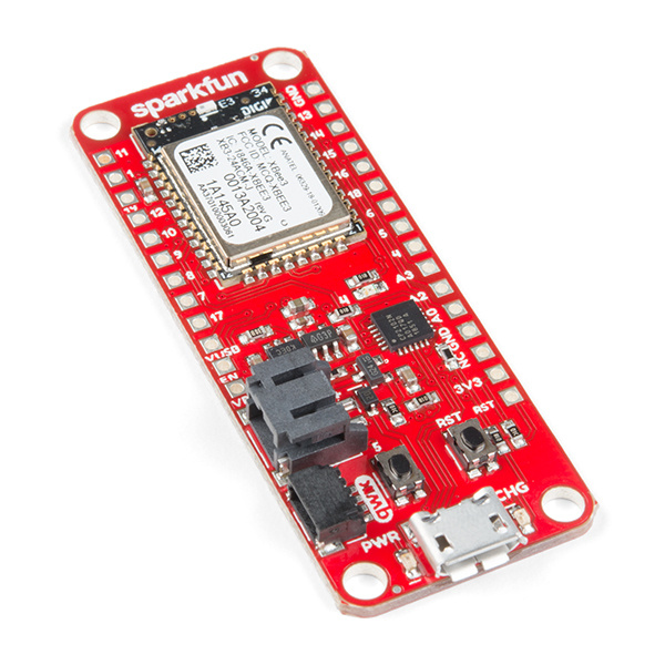
Who doesn't love a Bee? With these 2 versions of SparkFun's XBee3 Thing Plus - the XBee3 Thing Plus (u.FL) and the XBee3 Thing Plus (PCB Antenna), we've taken DIGI's XBEE3 802.15.4 and plopped it into the Thing Plus footprint and the result has us all abuzz. For all intents and purposes, the 2 variants are the same board - the difference being in the antenna.

Required Materials
To follow along with this tutorial, you will need the following materials. You may not need everything, depending on what you have. Add it to your cart with your choice of the XBee3, read through the guide, and adjust the cart as necessary.
Suggested Reading
If you aren’t familiar with the following concepts, we recommend checking out these tutorials before continuing.
How to Solder: Through-Hole Soldering
Serial Terminal Basics
Exploring XBees and XCTU
MicroPython Programming Tutorial: Getting Started with the ESP32 Thing
Three Quick Tips About Using U.FL
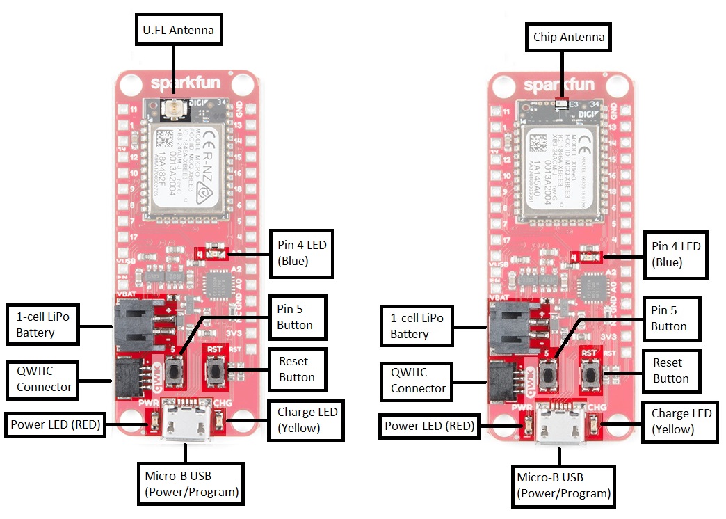
Hardware Overview
Whether you're using the u.fl version or trace antenna version , the XBee3 Thing Plus is chock full of functionality. The XBee3 module itself measures 13 mm x 19 mm and supports multiple protocols, including ZigBee, 802.154, DigiMesh, and BLE. Add into that the capabilities of SparkFun's Thing Plus and we're looking at an amazing amount of functionality.
XBee3 Features
- Voltage Range: 2.1-3.6V
- 2μA Power-down current
- 1MB of flash, 128kB of RAM
- +8dBm transmitting power (Up to 135mA)
- -103dBm receiving sensitivity (17mA)
- Supported protocols: 802.15.4, Bluetooth v4.0, Zigbee
- RF Data Rate: 250Kbps
- UART Data Rate: Up to 1Mbps
- Indoor range: Up to 200ft (60m)
- Outdoor (Line-Of-Sight): Up to 4000ft (1200m)
Peripherals and I/O
The XBee3 Thing Plus features your standard fare of hardware peripherals including:
- 20 general purpose input/output pins
- Up to four 10-bit analog to digital converter (ADC) channels (see note 1)
- Up to two 10-bit pulse width modulation (PWM) channels (see note 2)
- UART
- I2C
- SPI (see note 3)
1. There are three dedicated ADC channels, with the fourth connected to IO pin 1/SCL if I2C is not being used.
2. There is a dedicated PWM channel connected to IO pin 10, with the second connected to IO pin 11/SDA if I2C is not being used.
3. SPI is currently still under development from Digi and is not yet supported in MicroPython.
Powering the XBee3 Thing Plus
The two main power inputs to the XBee3 Thing Plus are USB and a single-cell lithium-polymer (LiPo battery. If both USB and the LiPo are plugged into the board, the onboard charge controller will charge the LiPo battery at a rate up to 500mA.
The 3.3V regulator on the XBee3 Thing Plus can reliably supply up to 600mA, which should be more than enough overhead for most projects. The XBee3 can pull as much as 135mA during RF transmissions. The output of the regulator is also broken out to the side of the board -- the pin labeled "3V3". This pin can be used to supply external components.
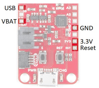
In addition to USB and battery connectors, the VBAT, and VUSB pins are all broken out to the sides of the board. These pins can be used as an alternative supply input to the Thing Plus. The maximum, allowable voltage input to VUSB is 5.8V, and VBAT should not be connected to anything other than a LiPo battery. Alternatively, if you have a regulated voltage source between 2.1V and 3.6V, the "3V3" line can be used to directly supply the XBee3 and its peripherals.
Software Setup
The XBee3 Thing Plus was designed to work with MicroPython and XCTU.
Setting Up XCTU
XCTU is free software, provided by Digi (the manufacturer of XBee), which we use to configure and manage XBees as well as test XBee networks. If you haven't worked with XCTU before, head on over to our Exploring XBees and XCTU tutorial to get set up.
Exploring XBees and XCTU
Firmware/Bootloader Update
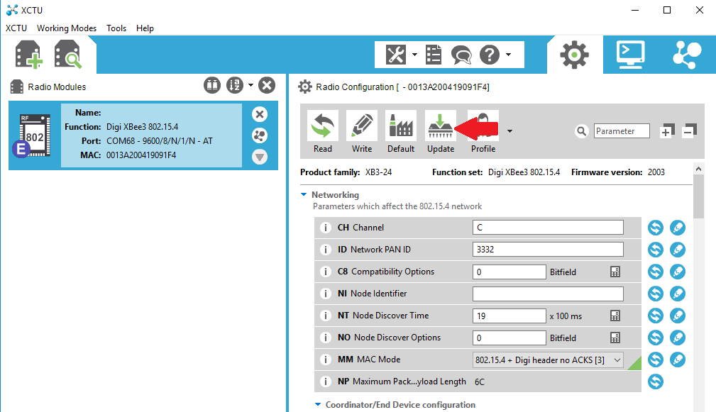
Once you have XCTU installed, presumably you'll have the XBee plugged in and visible in XCTU. If not, head on back to the Exploring XBees and XCTU tutorial to get yourself set up. Now you'll need to update the firmware, and likely the bootloader.
In XCTU, click on the Update button:
Make sure you have the latest selected and go ahead:
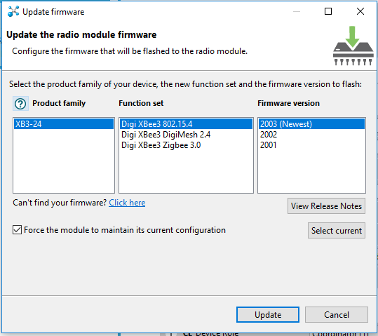
You'll be guided through a number of dialogs. If you are asked to update the bootloader, go ahead and do so.
Settings
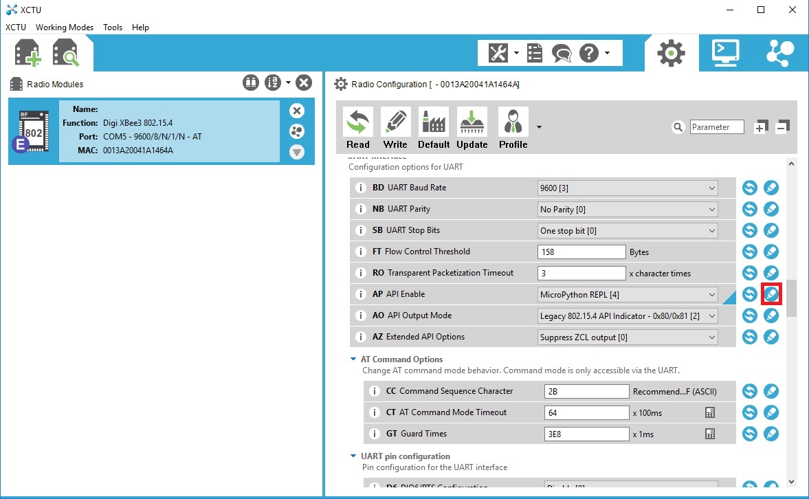
Most of the settings in the XCTU can be left alone. However, if you plan to upload or edit the code on your XBee, you'll need to enable the API and set it to MicroPython REPL.

Make sure to click the "Write" button to save your changes!
REPL (Hello, World!)
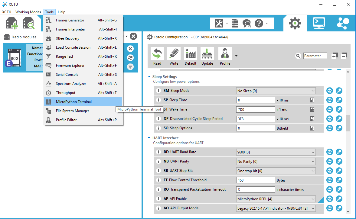
One of the easiest ways to interact with MicroPython running on the XBee3 Thing Plus is to enter commands via the REPL over a serial connection. This can be extremely helpful if you want to test out various parts of code before writing them down in a (slightly more permanent) text document that is then uploaded to the XBee3 Thing Plus. Fortunately, XCTU offers a MicroPython Terminal in its Tools menu!
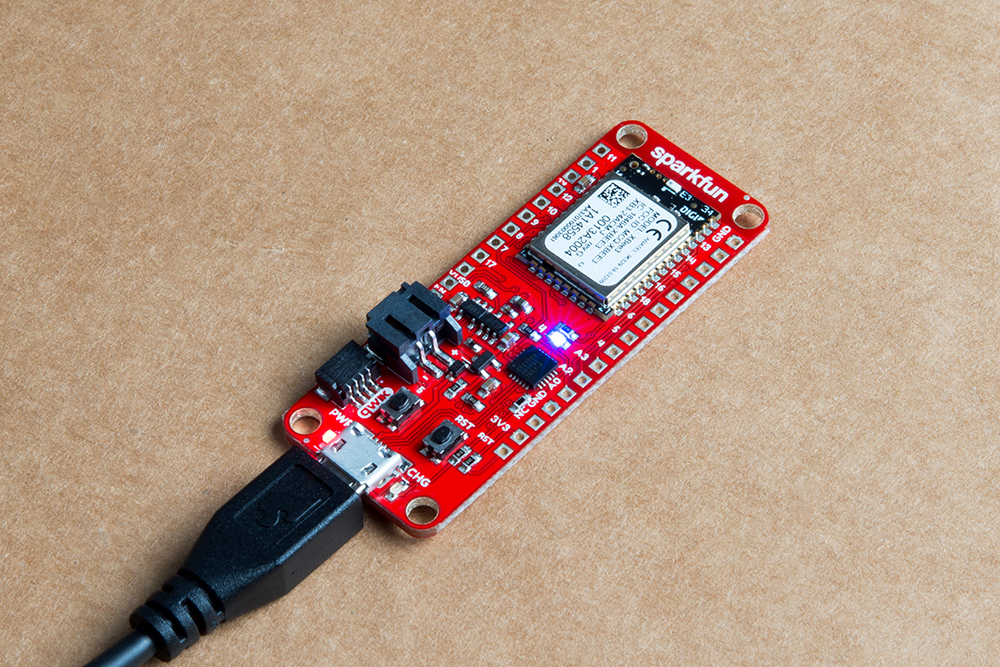
To start, connect the XBee3 Thing Plus to your computer using a USB micro-B cable. If you are on Windows, open the Device Manager and find out which COM port your XBee3 Thing Plus is associated with (for example, COM5). On macOS, it will likely be /dev/cu.usbserial-
Open up XCTU and load up your XBee3 Thing Plus as outlined in the Software Setup section. Make sure you have MicroPython REPL [4] selected under AP API Enable and make sure you've clicked the pencil button to write your changes to the XBee.
Accessing the MicroPython Terminal
The XCTU provides a MicroPython Terminal under the Tools Menu:
Once you have the terminal window available, click on Configure and make sure you select the correct COM port. Most of this should be pre-populated, but double-checking never hurts.
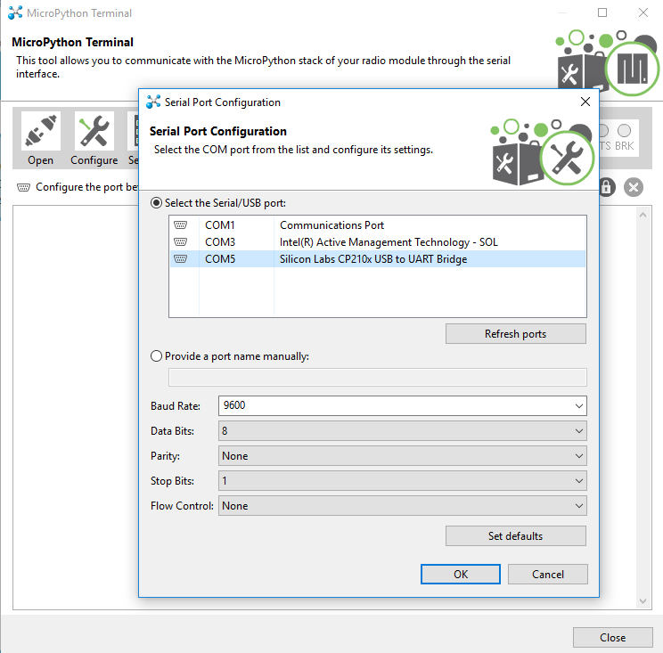
Once you're satisfied that everything is correct, click OK in the configuration window and the hit the Open button.
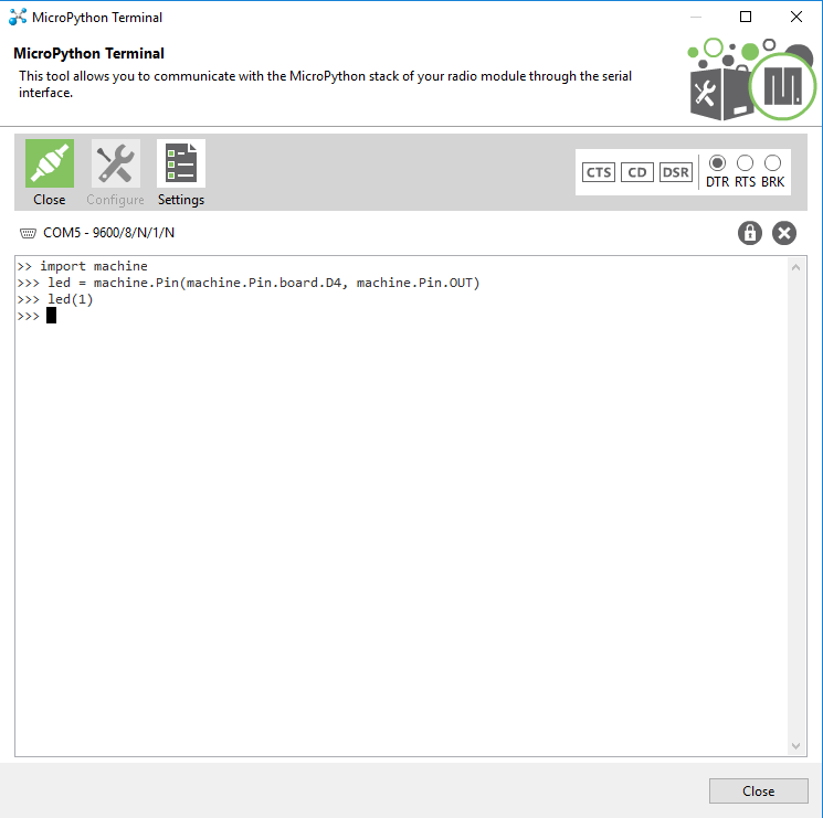
Once you have a connection, press enter once to get a REPL command prompt (>>>).
When you see that command prompt, enter the following commands one at a time:
language:Python
import machine
led = machine.Pin(machine.Pin.board.D4, machine.Pin.OUT)
led(1)
This should turn on the LED found on the XBee3 Thing Plus (the blue LED located at pin 4).
Type the following command to turn it off:
language:Python
led(0)
Code to Note:
The first thing we typed was import machine. machine is the MicroPython module that gives us control of the various general purpose input/output (GPIO) pins and special functions, such as I2C and interrupts. We use the keyword import to make all of the functions in the machine module available for us to use.
We then create a machine.Pin object and store it in the label led. When defining a machine.Pin object, we supply a number of arguments, including which pin number we want to use (the pin numbers can be found in white numbers on the side of the XBee3 Thing Plus) and how we want to use that pin (e.g. as an input or output).
Because we set the pin as an output (as given by machine.Pin.OUT), we can drive the pin to logic low (0 V) or logic high (3.3 V) by setting its value to 0 (logic low) or 1 (logic high). To drive the pin high, we write led(1). This has the effect of turning on the LED.
Similarly, we can turn the LED off with led(0), which sets the pin to 0 V.
Experiment 1: AutoRunning MicroPython
As we saw above, it is easy to control an LED by individually calling commands in the REPL. Here we are going to write our code to a file, upload that file to the XBee3 Thing Plus, and then set up the XBee3 Thing Plus to auto-run the MicroPython code.
There's a caveat to writing code that automatically runs on the XBee3 Thing Plus. If your code contains a forever loop, the MicroPython interpreter will continue to run your code (forever!) which means we will never get a REPL prompt, should we want/need one. We're going to upload code that runs a forever loop, but checks for a Button 5 press. When it detects that button press, it will drop to REPL.
Code Part 1: Push Button, Get REPL
In your text editor of choice, enter the following code:
language:python
import machine
import sys
import utime

# Pin definitions
repl_button = machine.Pin(machine.Pin.board.D5, machine.Pin.IN, machine.Pin.PULL_UP)

# Wait for button 5 to be pressed, and then exit
while True:

    # If button 5 is pressed, drop to REPL
    if repl_button.value() == 0:
        print("Dropping to REPL")
        sys.exit()

    # Do nothing
    utime.sleep_ms(1)
Save the code with the name main.py.
Run It
In most configurations of MicroPython, there are two files stored on the microcontroller: boot.py and main.py. As soon as the microcontroller receives power (or directly after a reset), the code in boot.py will be run. Then, main.py will run. Note that once main.py finished executing, it will be run again (over and over again forever).
Within the File System Manager, we do not see boot.py or main.py; instead we will be uploading our own main.py file to the XBee.
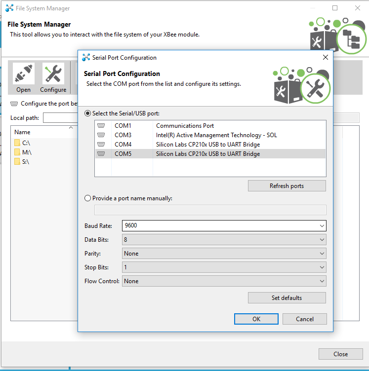
In XCTU, under Tools, select the File System Manager. Go ahead and click on the Configure button, make sure you have the correct port and baud rate selected, and then click OK.
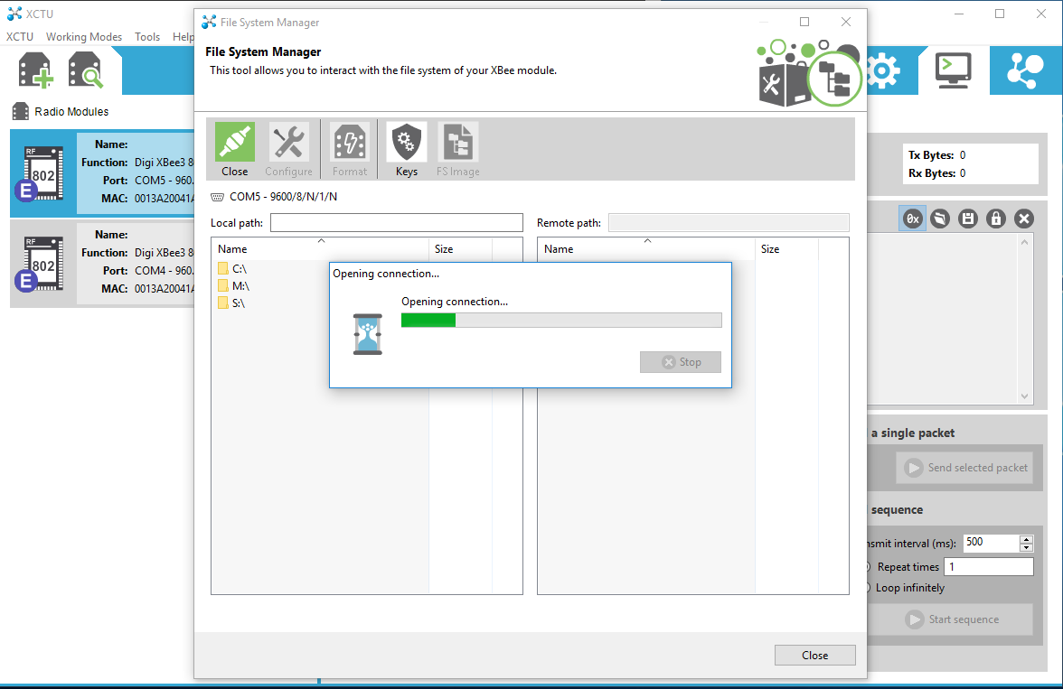
Next, click on the Open button, and once the connection is established, you should see your own file system on the left, and the XBee's file system on the right.
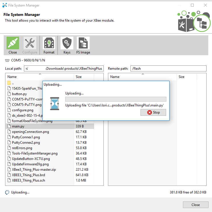
In the left side, navigate to your main.py file, and then drag that to the XBee's window on the right. The file will upload to the XBee!
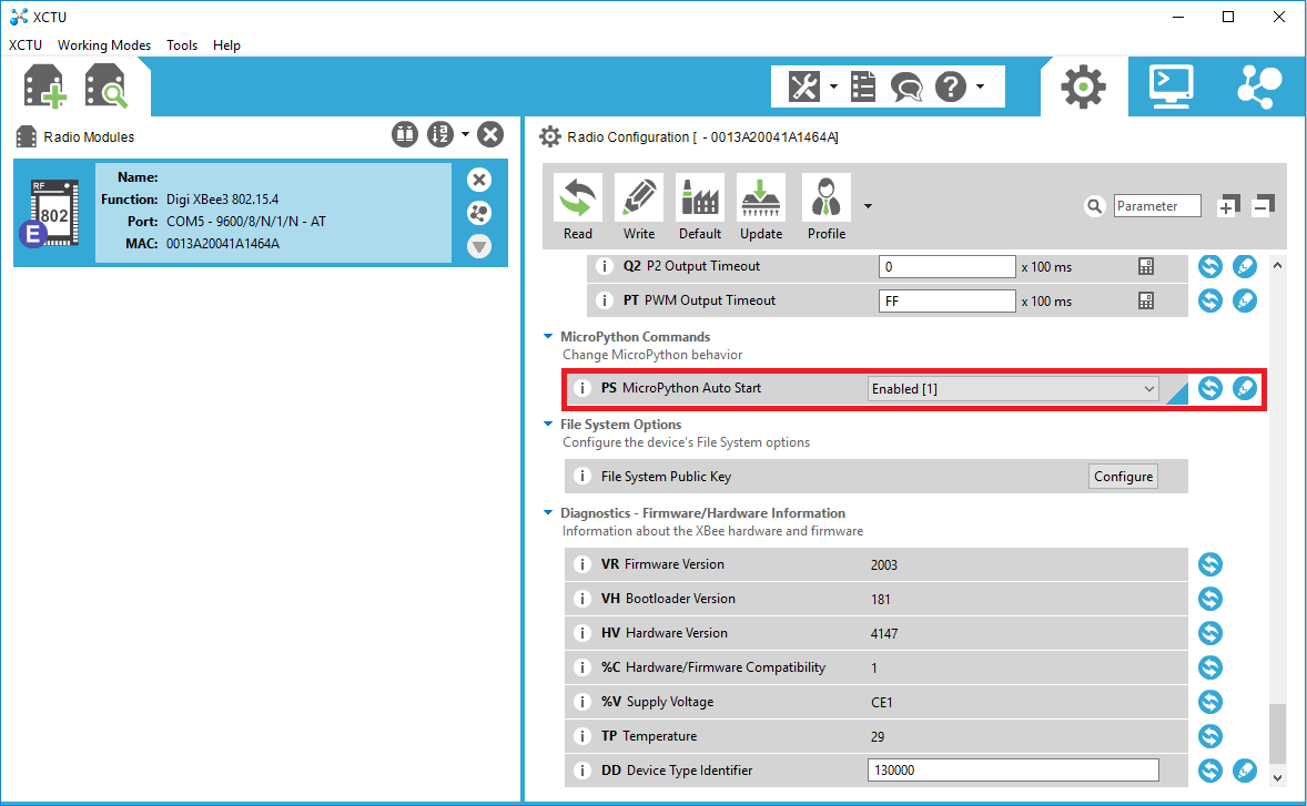
Enable AutoRun
If you wish to have your main.py file automatically run on your XBee, you'll need to go back to XCTU and enable the MicroPython Auto Start. Make sure you click on the pencil button to write your changes to the XBee!
After uploading your code and enabling autostart, go ahead and hit the RST button on your XBee. Your code should now automatically start running. However, because our code simply exits on a button push, there is nothing to see here. Go ahead and hit the Close button on the top left to close the connection, and then exit out of this dialog.
Back in XCTU, select Tools->MicroPython Terminal. Again, verify that you have the correct COM port and baud rate selected, and then open the connection to your XBee. You should see a blank terminal window, and even if you try typing some characters, nothing should appear.
Press the 5 button on your XBee3 Thing Plus board.

As soon as you hit that button, you should see a message appear in your serial terminal saying "Dropping to REPL" followed by the MicroPython version number and a command prompt (>>>).

Code to Note
Our program is relatively simple. We first import the machine, sys, and utime modules. The machine module allows us to control connected hardware, like pins. The sys module gives us access to underlying interpreter values and the ability to exit out of our forever loop in main.py. Finally, the utime module allows us to get the local machine time (assuming we have a connected real-time clock) or tell our program to wait for a specified amount of time.
Much like in our REPL example, we create a machine.Pin object for pin 5, but we make it an input this time. We supply a third argument: machine.Pin.PULL_UP. This says that we want to enable the XBee's internal pull-up resistor for pin 5. This allows the voltage on pin 5 to stay at 3.3 V until we push the onboard button, which subsequently pulls the voltage on the pin down to 0 V. We can use this technique to determine if the button has been pressed.
Everything indented under while True: runs forever. Each line is executed sequentially before returning to the top of the while loop.
Within the loop, we check to see if the button has been pressed:
language:python
if repl_button.value() == 0:
    print("Dropping to REPL")
    sys.exit()
If it has, we print a message out to the serial terminal and then call sys.exit(), which raises a SystemExit exception. This will force the program to exit (and the MicroPython interpreter will perform any garbage collection or cleanup as necessary).
If no button push is detected, we tell the XBee to do nothing (sleep) for 1 ms:
language:python
utime.sleep_ms(1)
This process is repeated again within the while loop.
Code Part 2: Blinky
In a text editor, enter the following code:
language:python
import machine
import sys
import utime

# Pin definitions
repl_button = machine.Pin(machine.Pin.board.D5, machine.Pin.IN, machine.Pin.PULL_UP)
led = machine.Pin(machine.Pin.board.D4, machine.Pin.OUT)

# Blink forever
while True:

    # If button 5 is pressed, drop to REPL
    if repl_button.value() == 0:
        print("Dropping to REPL")
        sys.exit()

    # Turn LED on and then off
    led.value(1)
    utime.sleep_ms(500)
    led.value(0)
    utime.sleep_ms(500)
Save the code to your main.py file on your local file system (overwrite it).
Run It
Make sure you've closed out of the previous connection, and then upload your code via the File System Manager - exactly the same way you did in Code Part 1. You will want to overwrite or first delete the main.py file that exists on your XBee3 Thing Plus file system.
The onboard blue LED should begin blinking on and off every second. If it does not do so right away, push the RST button on the board.
Open up a MicroPython Terminal and connect to your XBee3 Thing Plus. Press and hold button 5 until the blinking LED stops. You should also see a REPL prompt appear.
Code to Note
This time, we combined parts from our first REPL example and our button example. We added the following part in the while loop:
language:python
led.value(1)
utime.sleep_ms(500)
led.value(0)
utime.sleep_ms(500)
Much like we saw in the REPL example, we turn the LED on with led.value(1) and turn it off with led.value(0). We sleep 500 ms between each action so that we can see the LED blinking.
At the top of our while loop, we added our "drop to REPL" button press code to make debugging or interacting with the XBee3 Thing Plus easier. Note that you need to hold down button 5 this time, as it can take over 1 second for one iteration of the while loop to complete. Execution needs to return to the beginning of the loop before checking for a button 5 press again.
Experiment 2: Pulse Width Modulation (PWM)
Pulse width modulation is the technique of switching a digital signal on and off very quickly to control a variety of electrical components. By varying the amount of time a signal is on vs off, you can vary the amount of electrical power provided to a component. We can use this, for example, to dim an LED or control the speed of a motor. To learn more about PWM, see this tutorial.
In this example, we are going to create a simple LED animation that occurs as long as a button is held down.
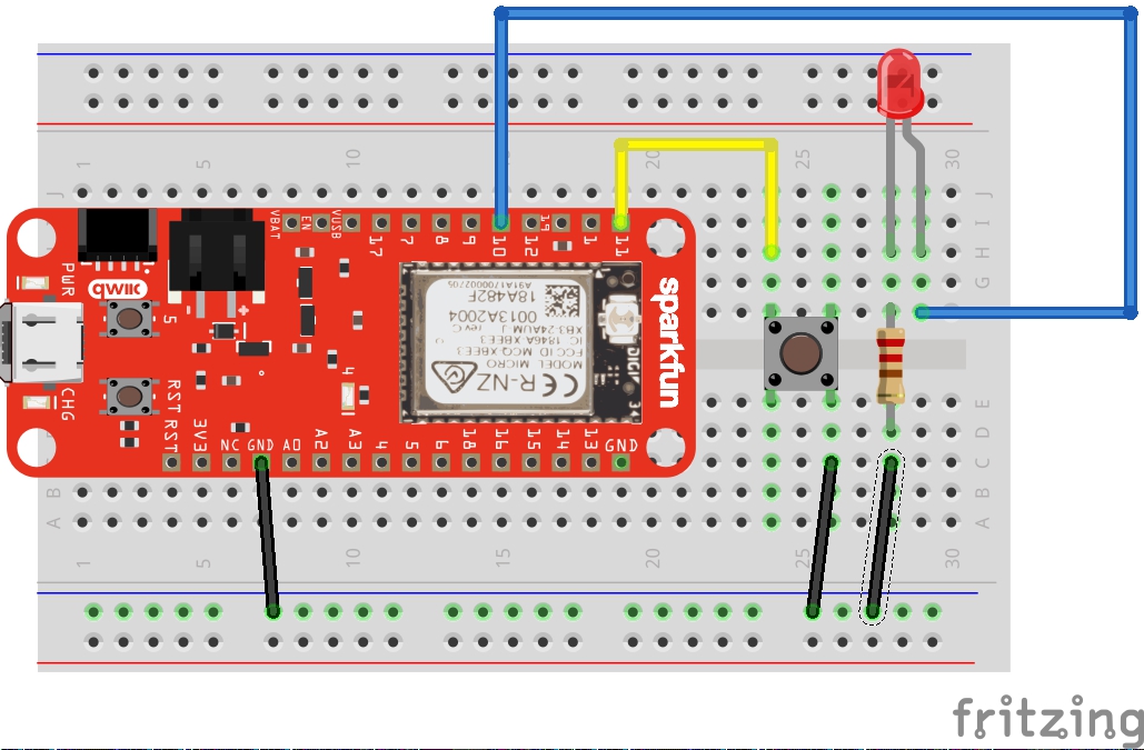
Hardware Connections
Connect an LED and a button to the XBee3 Thing Plus as per the following diagram:
Code: LED Animation
Open a new file in your favorite text editor, enter the following code:
language:python
import machine
import sys
import utime

# Pin definitions
repl_button = machine.Pin(machine.Pin.board.D5, machine.Pin.IN, machine.Pin.PULL_UP)
repl_led = machine.Pin(machine.Pin.board.D4, machine.Pin.OUT)
button = machine.Pin(machine.Pin.board.D11, machine.Pin.IN, machine.Pin.PULL_UP)
pwm_pin = machine.Pin(machine.Pin.board.D10, machine.Pin.OUT)

# Create a PWM object out of our pin object
pwm = machine.PWM(pwm_pin)

# Slowly fade LED brightness
while True:
    # If button 5 is pressed, turn on LED and drop to REPL
    if repl_button.value() == 0:
        print("Dropping to REPL")
        repl_led.value(1)
        sys.exit()

    # Increase brightness of LED if button is held
    for i in range(1024):
        if button.value() == 0:
            pwm.duty(i)
            utime.sleep_ms(2)
        else:
            pwm.duty(0)
Save your file as main.py on your local file system, overwriting your previous main.py file. Upload the code to your XBee3 Thing Plus as outlined in Experiment 1. Press RST to auto-run the new main.py file.
After the code has been uploaded and the board reset, hold down the button (the one on the breadboard that is connected to pin 11. You should see the LED slowly brighten, turn off, and then begin the brightening animation over again as long as the button is held down.
Code to Note
Much of the code should look familiar from the previous experiment, as we are creating a machine.Pin object for our LED and another one for our button. Note that we are keeping the "drop to REPL" snippet in, as we always want a way to exit out of our code's main loop.
The main difference is that we are creating machine.PWM object out of our machine.Pin object (the pin object that we've created with the pwm_pin variable. With the machine.PWM object, we can call the pwm.duty() method, which allows us to control the amount of on vs. off time on pin 11. A duty cycle of 0 means that the pin is always 0 V. A duty cycle of 511 (about half of 1023) means that pin 11 should rapidly switch between 0 V and 3.3 V equally (50%). Finally, a duty cycle of 1023 means that pin 11 should be always on (always at 3.3 V). Again, refer to the Pulse Width Modulation tutorial for more information on pwm and duty cycles.
By placing pwm.duty() inside a for loop, we can increase the brightness one stage at a time with a 2 ms delay between each stage. This ultimately gives the effect of a slowly increasing LED brightness.
Notice that we check for button 5 at the beginning of the for loop. That means that you need to hold down button 5 until the for loop (LED animation) has completed one iteration before the program realizes you've pressed the button (and should therefore exit to REPL). To help you know when you have successfully exited the program into REPL, we added repl_led.value(1) to turn on the onboard blue LED.
Troubleshooting
If your product is not working as you expected or you need technical assistance or information, head on over to the SparkFun Technical Assistance page for some initial troubleshooting.
If you don't find what you need there, the SparkFun Forums are a great place to find and ask for help. If this is your first visit, you'll need to create a Forum Account to search product forums and post questions.
Resources and Going Further
Now that you've successfully got your XBee3 Thing Plus up and running, it's time to incorporate it into your own project! For more information, check out the resources below:
SparkFun XBee Resources
Digi XBee Resources
- XBee 3 Hardware Reference Manual
- XCTU User Guide
- Digi Micropython Programming Guide
- XBee Python Library
- Digi XBee Support Documentation Page
MicroPython Resources
Need some inspiration? Check out some of these other XBee related tutorials: