Working with Wire
 Paul Smith,
  bboyho
How to Crimp an Electrical Connector
An electrical connector is a device for joining electrical circuits together using a mechanical assembly. The connection may be temporary or serve as a permanent electrical joint between two wires. There are hundreds of types of electrical connectors. Connectors may join two lengths of wire together or connect a wire to an electrical terminal.
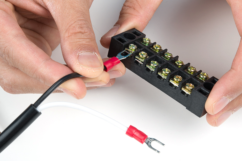
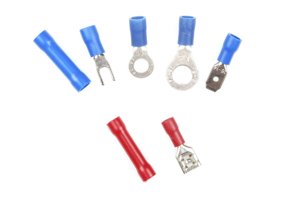
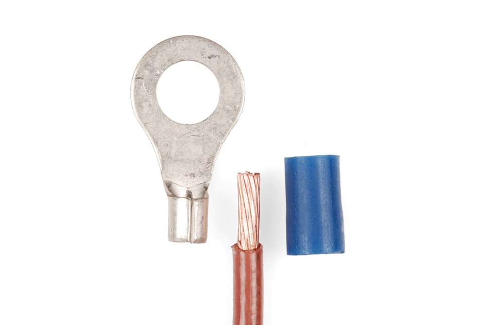
Below area few connector types. On the far, upper left, we have an insulated splice connector to connect two wire ends together. To the right, the forked connector (a.k.a. spade, or split ring) is useful for connecting wire to screw terminals by sliding the fork into a screw terminal's socket. Screws can be partially screwed in before installing the terminal. The ring terminals in the middle are also useful for connecting wire to screw terminals. While the ring terminal provides a more reliable connection, you would need to completely remove the screw before installing the terminal. On the far, upper right we have a male spade connector (a.k.a. blade). These can slide into the female spade connector (a.k.a. double crimp) that is shown on the bottom right. Depending on the design and application, these connectors can come in different flavors like flanged fork or locking ring terminal.
These connectors can also come in different sizes and ratings. The image shown below shows a 1/4" and 2.8mm female spade connector.

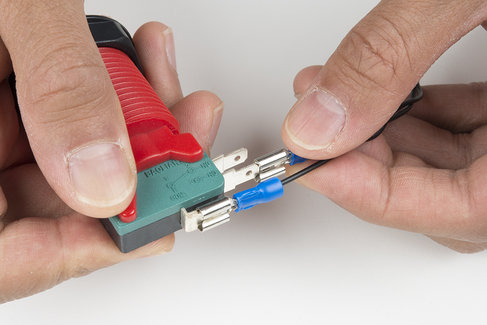
You will want to match the size of the connectors for a secure connection. The image below shows 1/4" female spade connectors connecting to a microswitch's male spade terminals.
What is a Crimp?
The word crimping in this context means to join two pieces of metal together by deforming one or both of them to hold the other. The deformity is called the crimp.
The Tool
In order to crimp connectors onto a wire, a special tool is require for the crimp pin. There are several different styles of crimpers available depending on the crimp pin.
Ratchet Crimp Tool
The best crimper has a built-in ratchet. As the handles are squeezed together, it will ratchet and prevent the jaws from opening back up. When enough pressure has been applied, the ratchet will disengage and release the crimped part. This ensures enough pressure has been applied. This style of crimper also has a wide jaw to cover more surface area on the connector.
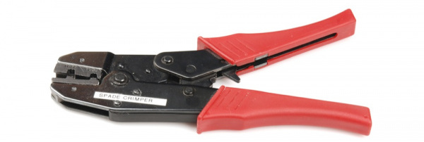
Depending on the size of the connector, the type of the "die" (i.e. the crimp tool's head) will be sized differently. The crimp tool below uses a different die to crimp smaller crimp pins that slide into a pin connector housing.
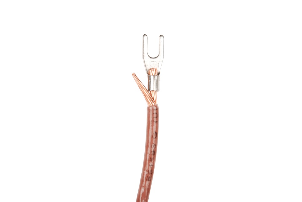
The images below show different gauges of wire crimped to forked connector and crimp pin for a polarized connector.
 |
 |
| Fork Connectors Crimped for a Wall Adapter | Crimp Pin Crimped Before Being Inserted to a Plastic Housing |
Manual Crimp Tool
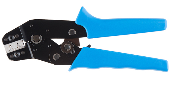
Manual crimping tools can achieve nearly the same results, although it requires the user be much more vigilant. This style of crimper is generally less sturdy. Attention must be given while crimping to ensure the jaws are lined up properly on the connector. Misalignment will cause a less than desirable crimp connection. Over time, wear and tear from normal usage can also cause the jaws to become separated and not close fully. Generally, squeezing it as hard as possible will be sufficient. The fancy wire stripper shown below can be used with quick disconnects. The tool can also be used to cut wire and strip wires/cables.
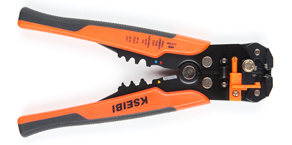
While the self-adjusting wire stripper is a bit harder to work with than a ratchet, it has the ability to strip, cut, and crimp a quick disconnect.
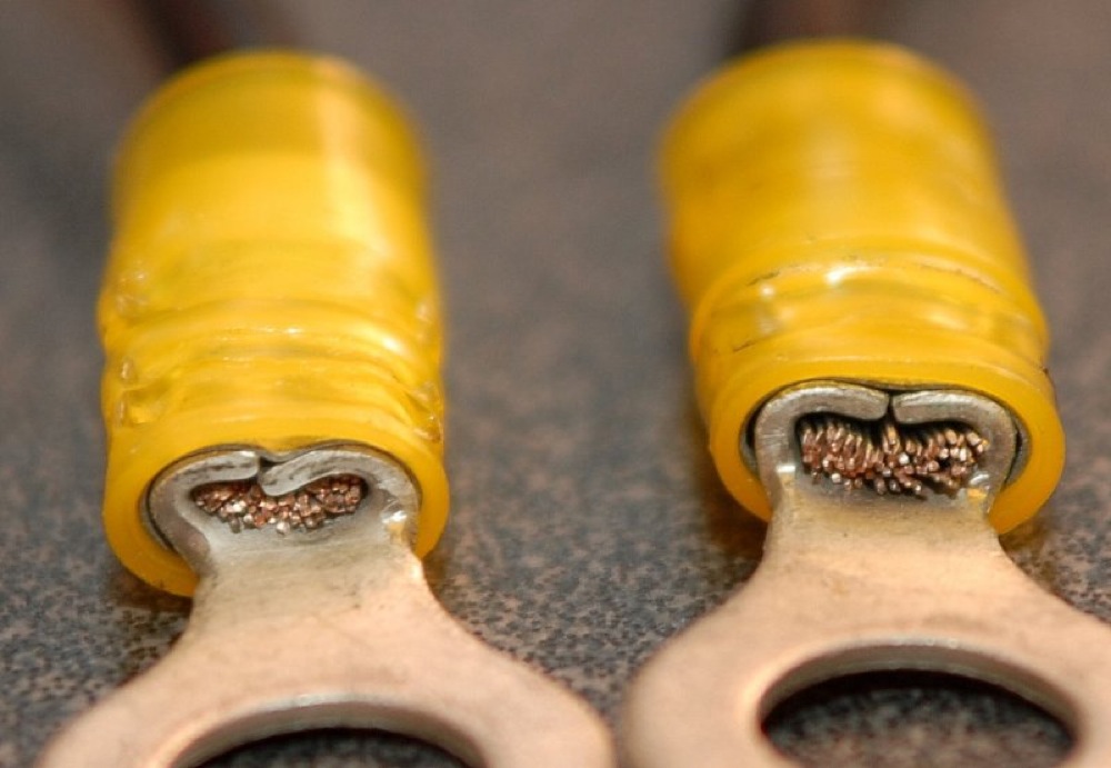
Why is this level of perfection required? A poor crimp leaves air pockets between the wire and connector. Air pockets allow moisture to collect, moisture causes corrosion, corrosion causes resistance, resistance causes heat, and may ultimately lead to breakage.
Crimping a Quick Disconnect Connector
There are several arguments for and against using solid core wire with crimp connections. Many believe crimping to solid core wire creates a weak point in the wire, which can lead to breakage. There is also a greater chance for a crimp connection to come loose with solid core wire because the wire will not conform to the terminal as well. If you must use solid core wire, it is a good idea to solder the wire in place after you crimp it.
First, the correct size wire must be chosen for the terminal size, or vice versa. We'll assume that you are using stranded wire so that th wire conforms to the crimped connection. Next, strip the wire. The amount of exposed wire should be equal to the length of the metal barrel on the connector, usually around ¼” or so. If the stripped wire fits up into the metal portion of the barrel with little or no free space, the connector is the right size.
The wire should then be inserted until the insulation on the wire touches the end of the barrel.
The wire and terminal are then inserted into the crimper. The color of the terminal’s insulation needs to be matched with the same color on the crimping tool. So if the terminal’s insulation is red, use the spot marked by the red dot on the crimpers. Alternatively, if the crimper does not have color markings, use the gauge markings on the side.
The terminal should be sitting horizontal with the barrel side up. The tool is then held perpendicular to the terminal and placed over the barrel, nearest to the ring (or other connection type). To finish the crimp, the tool is squeezed with a considerable force. In general, it is almost impossible to ‘over crimp’ a connection.
For a detailed examples of good and bad crimped pin, check out the following from JST!
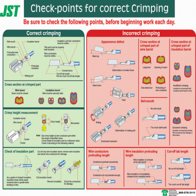
Click on image for closer view.
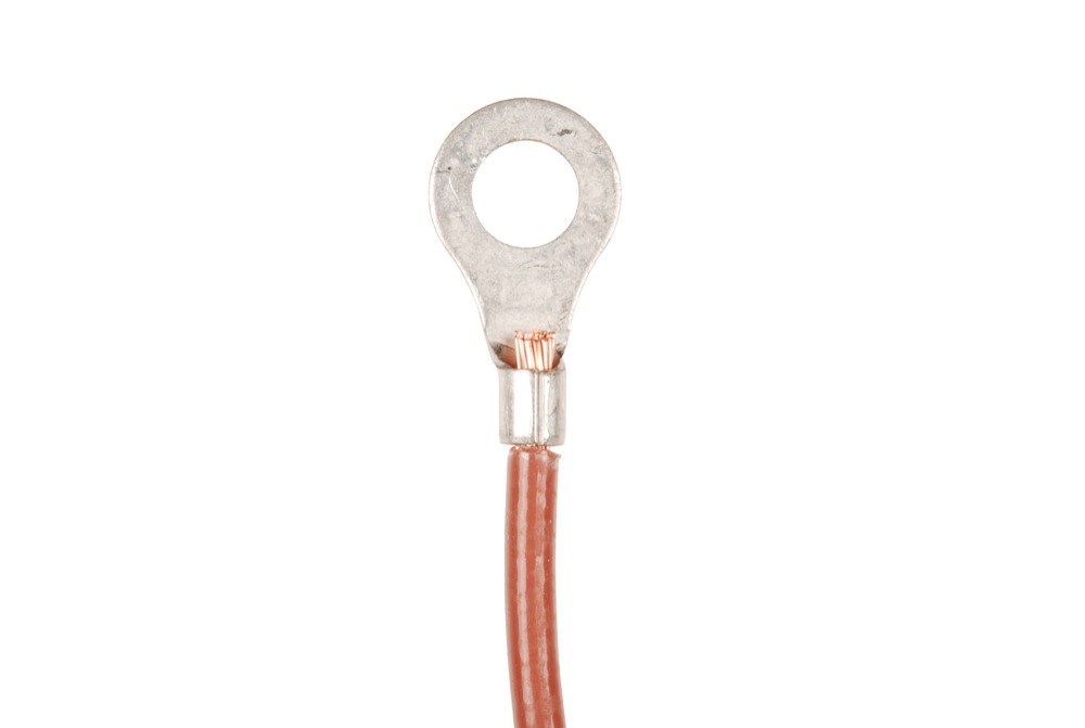
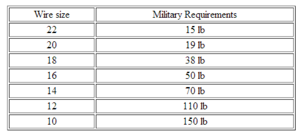
After the crimp is completed, the wire and connector should still hold together after trying to pull them apart with great force. If the connection can be pulled apart, the crimp was not done correctly. It is better to have the crimp fail now, versus after it has been installed in its application. Below is a military spec chart for crimped connections.

Keep in mind, that adding solder will add stress to the joint due to mechanical vibrations and thermal cycling causing joint failure. Soldering can also increase resistance at the joint. For low power applications, users should not notice a significant difference.
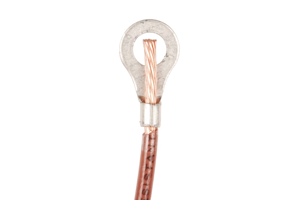
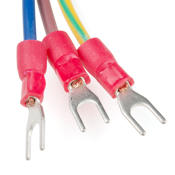
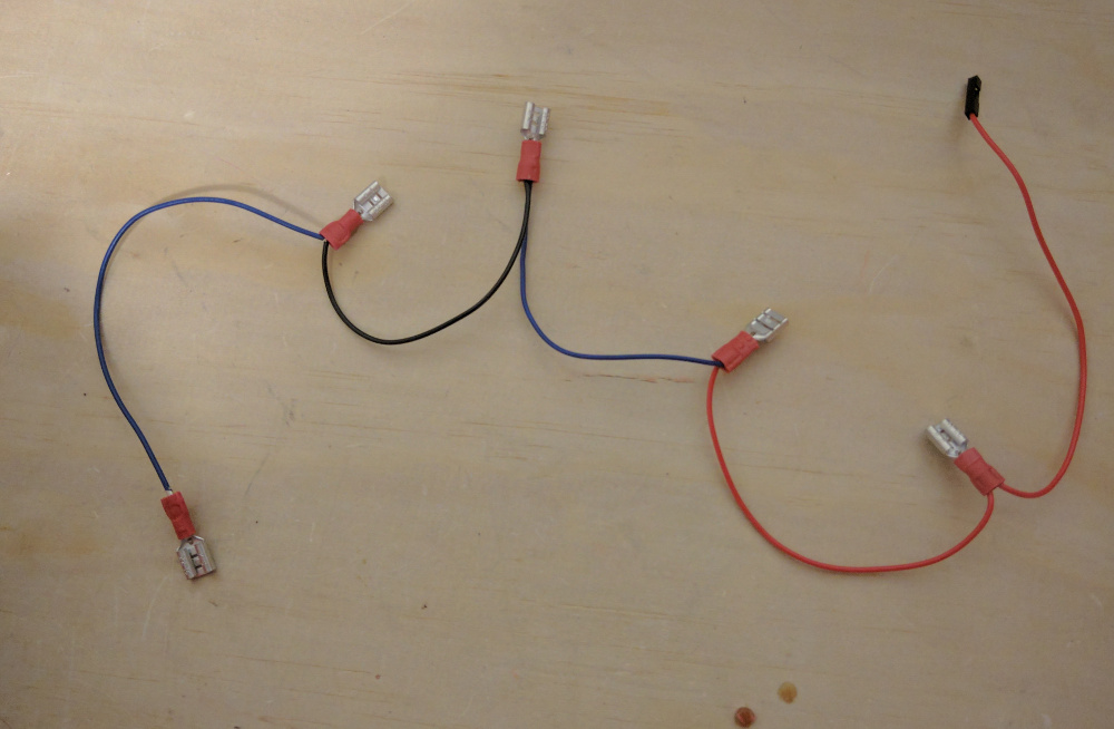
The image below demonstrates two wires crimped with female spade headers for the middle connections. In this case, the crimped wires were used to connect multiple devices to ground.
Crimping a Crimp Pin
Remember, there are hundreds of types of electrical connectors out in the world. Depending on the design, the connector can be designed in a way to fit into a plastic housing. Instead of a barrel crimping down on a wire, the connector may include two crimp tabs (i.e. wings) to crimp over wire and its insulation. The additional crimp tabs for insulation provide strain relief. The crimp pin may also have a locking tab and terminal stop when the pin is inserted in a plastic housing.
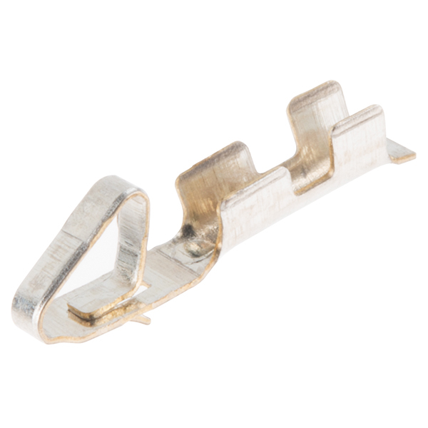 |
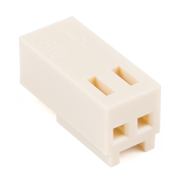 |
| Crimp Pin Cut from Reel for Polarized Connector | Plastic Housing for Polarized Connector |
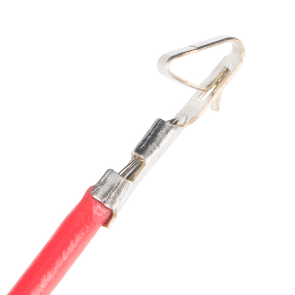
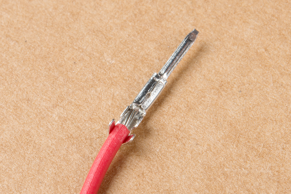
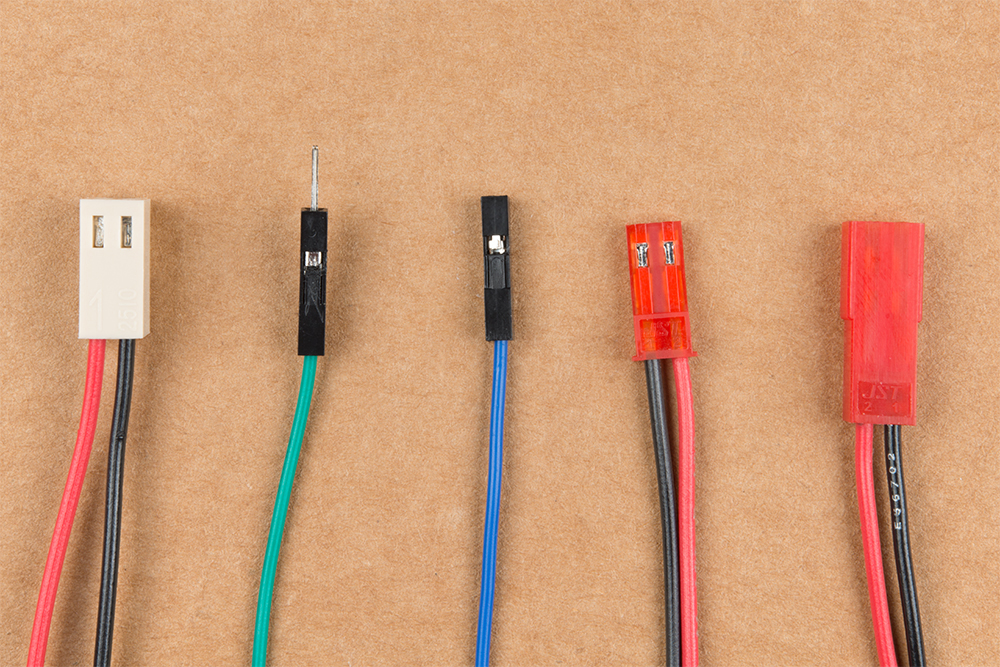
One example can be found in the pre-terminated, premium jumper wires. They are used for connecting to PCBs designed with 0.1" PTH pads. Below is an image of a few crimped pins before being inserted in their plastic housing. On the left is a crimp pin to fit inside a polarized housing. On the center is a female pin used to mate with the male pin on the right.

The process is a bit more tedious since you are working with smaller pins. Depending on your level of experience, this can be time consuming. However, users can create custom wire lengths and cables for a project.
First, cut and strip a piece of wire. Make sure to match the wire gauge with the crimp pin's specifications. In this case, we will use 22 AWG stranded hook-up wire to connect to the JST RCY connector as recommended by the crimp pin's datasheet. After removing the crimp pin from it's metal strip, align the wire strands to the conducting tab and the insulator to the insulator tab to check if the wire meets the crimp pin's specifications.
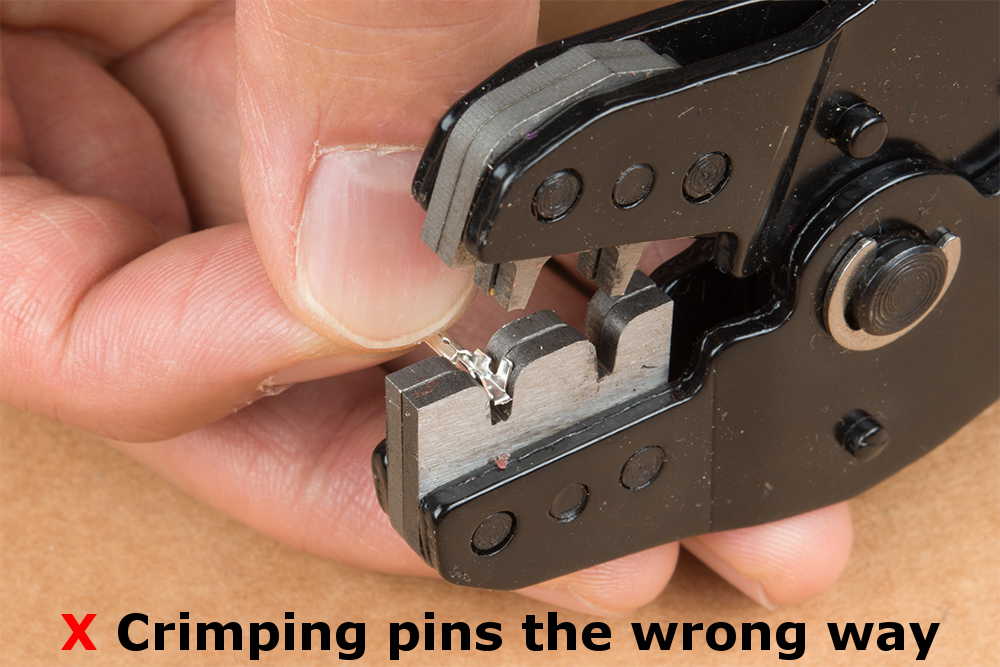
If the wire and stripped sufficiently, insert the crimp pin into one of the crimp tool's jaw. You may need to bend the insulator's tabs inward to fit. We'll use the bigger jaw.
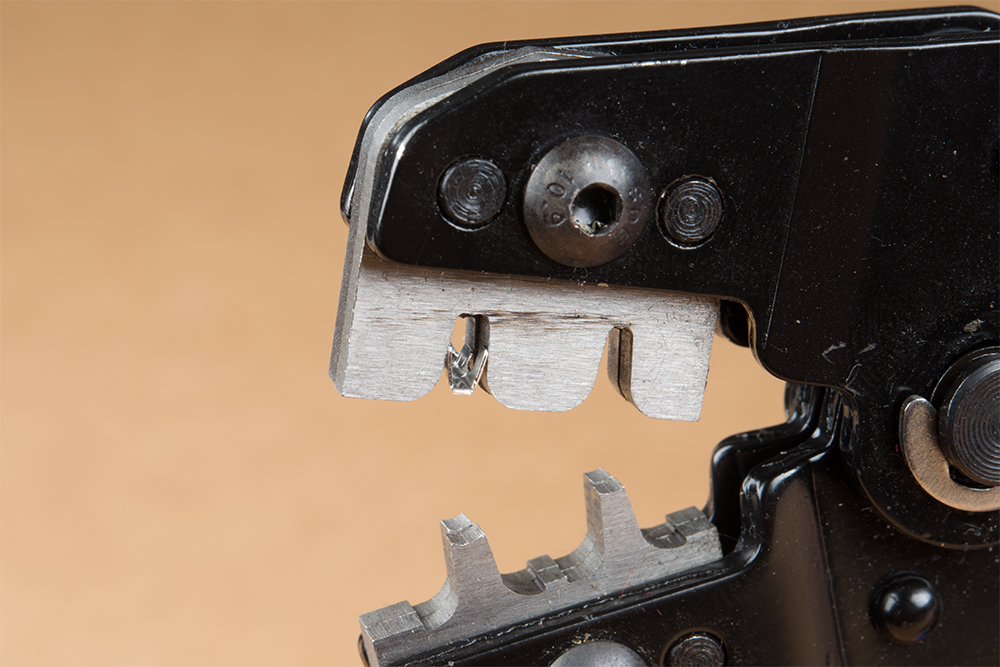
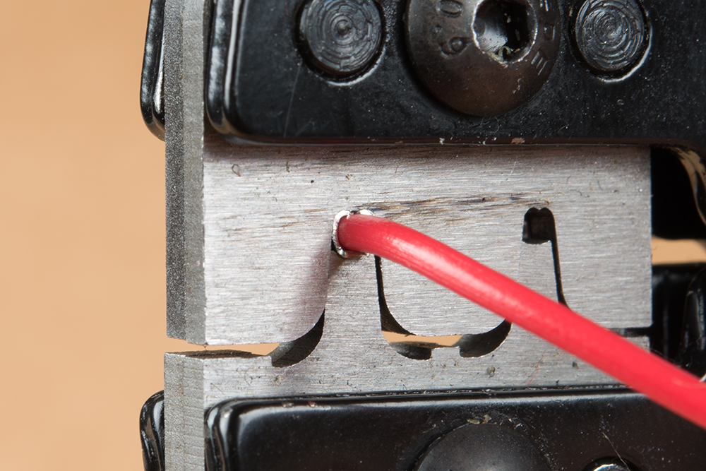
Make sure to take note grooves of the crimp tool when inserting the crimp pin into the die. If you observe closely, there are two semicylindrical grooves cut on one side of the jaw while the other has one groove. The side that has two grooves will be used to crimp the tabs. Additionally, half of the die is recessed for the insulator tab.
 |
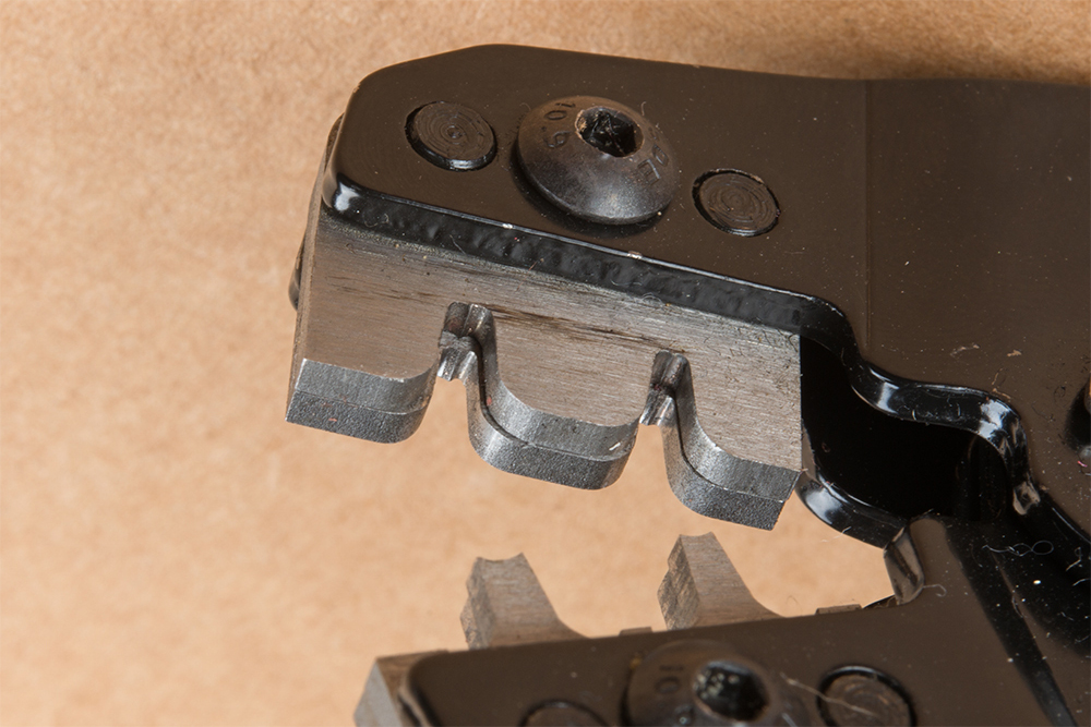 |
| Side View of the Ratcheted Crimp Tool | Close-Up of Crimp Tool with Two Grooves and Die Recessed for Insulator Tab |
Slowly close the ratcheted crimp tool to hold the crimp pin in place and insert the stripped wire. You may need to adjust the crimp pin so that its insulator tab is flush with the die.
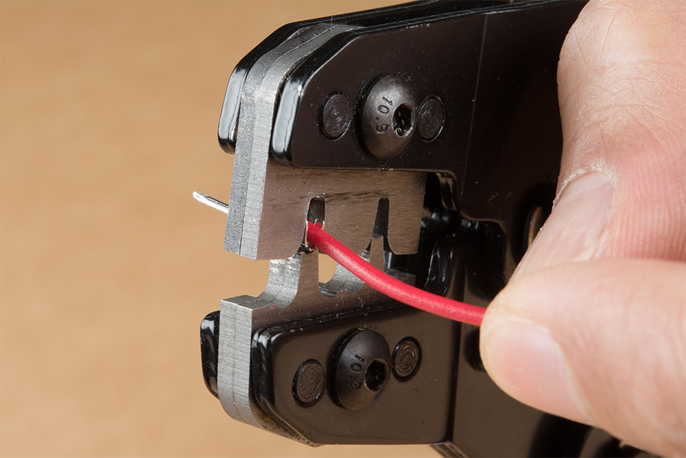
When ready, slowly squeeze the handles more to continue crimping the tabs. If something is not right and you are using a ratcheted crimp tool, flip the safety release pin just above the handle. Continue squeezing the handle until the ratchet releases automatically to finish the crimp.
Carefully, remove the crimped pin out of the crimp tool. Observe the crimped tabs. You should see something similar to crimped pins below. If necessary, you may need to re-insert the pin back into the jaws to sufficiently crimp the the tabs. The crimp pin on the far left was partially crimped and needed to be placed in the smaller jaw for a proper crimp.
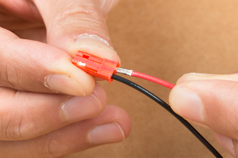
When ready, insert the crimped pin into its respective housing. In this case, the crimped female pin was inserted into its respective JST RCY connector housing. Make sure to match the locking tab with hole in the plastic housing.
When finished, the wire should snap into its respective housing. Below are a few crimped pins in their respective housing. On the far left, we have crimped pins used for the polarized 1x2 "Molex" connector. The two on the right with black housing is an example of crimped pins used with the standard 0.1" headers. Finally, the crimped pins in the red housing are used for the JST RCY connector.
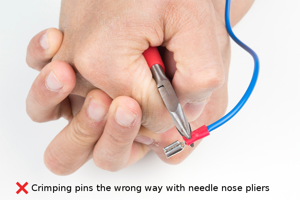
Common Mishaps
Below are a list of common mistakes when crimping quick disconnects and crimp pins. We'll use a quick disconnect for demonstration.
Wrong size connector for the wire or wrong size wire for the connector.
Be cautious not to strip too much insulation off.
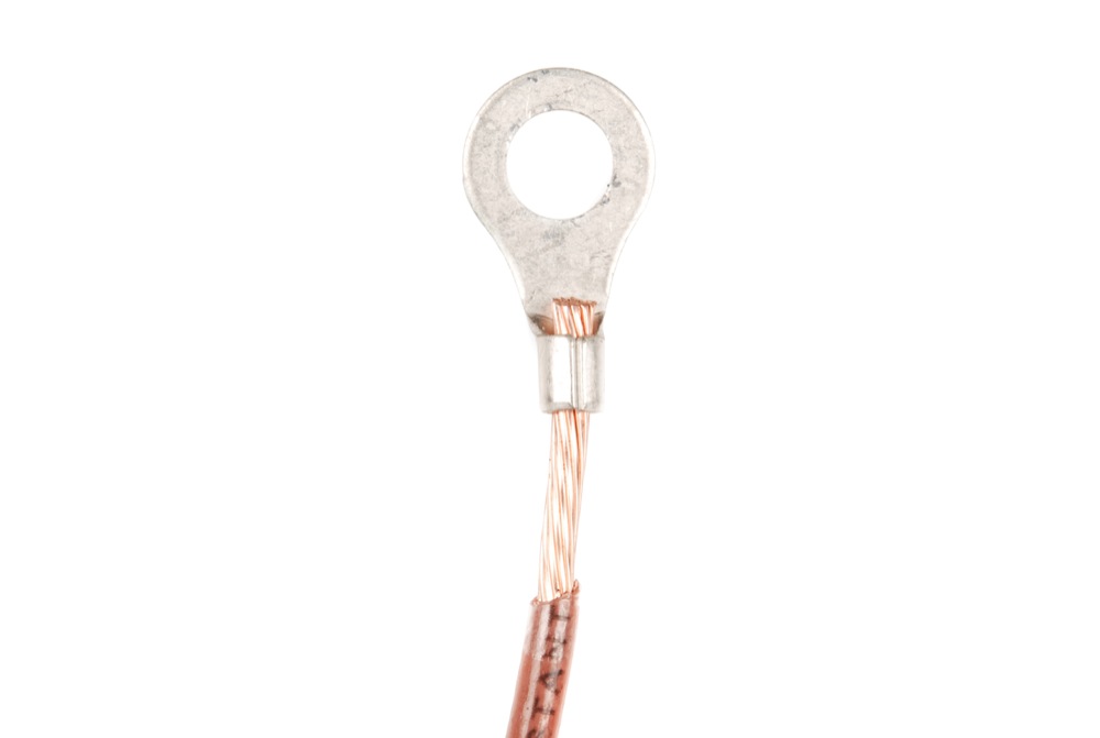
It is also worth mentioning that, while not necessarily harmful, The wire should not be protruding too far past the barrel. If this happens, trimming the wire is recommended.