Wireless Timing Project
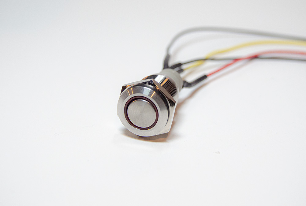
Metal Indicator Pushbutton
We saved this step for last because you will need to size your hookup wire to fit within your casing. For this step, we used some hookup wire, lead-free solder, a soldering iron, heat shrink, and a heat gun. For those looking to get their hands on this equipment, check out the list below.
To get started, we recommend soldering your hookup wire to the headers on the pushbuttons. Our very talented BBOYHO has created this incredible table to show us the solder points on the momentary pushbutton.
| Component | Component Pin | ESP32 I/O Pin |
|---|---|---|
| Red Momentary Metal Pushbutton | + : LED Anode Side | 13 |
| NC1: Normally Closed Pin | ||
| NO1: Normally Open Pin | RESET | |
| C1: Common Pin | GND | |
| -: LED Cathode Side | GND |
It’s best to do all soldering in one sitting to mitigate going back and forth between setups. Please be sure that your wire is long enough to reach the button within your casing. Our setup had roughly 5 inch cuts for each wire. Once you have soldered the button leads, place some heat shrink on the leads and secure them using your heat gun.
Now, we are ready to place the buttons inside our casing.