Wireless Controlled Wearable EL Wire Dance Suit
Introduction
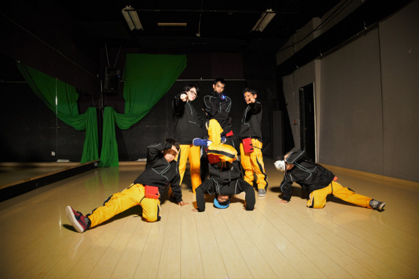
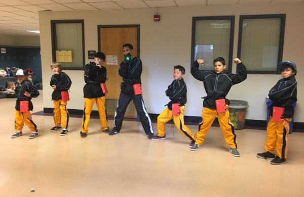
In this tutorial, we will build an EL wire dance suit that can be controlled by a wireless glove controller!
Suggested Reading
If you aren’t familiar with the following concept, we recommend checking out these before continuing.
How to Solder: Through-Hole Soldering
Exploring XBees and XCTU
Getting Started with Electroluminescent (EL) Wire
EL Sequencer/Escudo Dos Hookup Guide
Additionally, this project builds upon the following tutorials.
Wireless Glove Controller
EL Wire Hoodie
EL Wire Pants
How to Make a Custom EL Wire Extension Cable
Modifying Your EL Wire Inverter
Understanding Your Circuit
Glove Controller
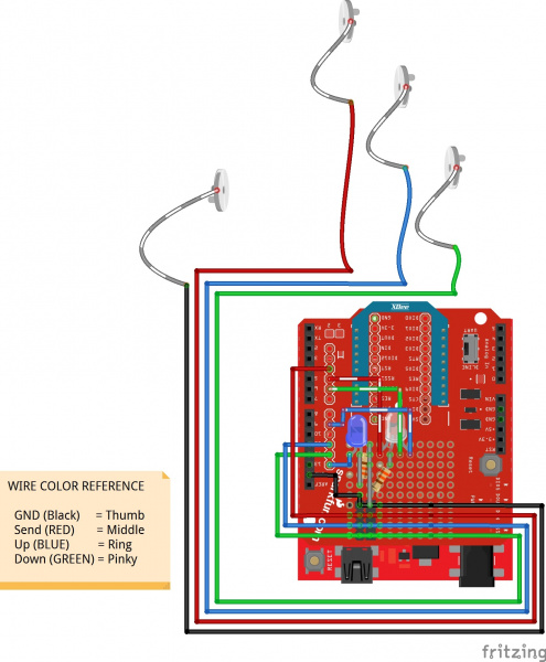
If you have not already, make sure to check out this tutorial on making a wireless glove controller.
Wireless Glove Controller
The XBee configuration and circuit used in the tutorial is the same as the one used to control each of the EL Sequencers.
Remote EL Sequencers
Each dancer has a remote EL Sequencer attached to their suit. If you have not already, make sure to check out the following tutorials to controlling each channel of the EL Sequencer, modify your inverter, and to make your own simple EL Wire suit.
EL Sequencer/Escudo Dos Hookup Guide
EL Wire Hoodie
EL Wire Pants
How to Make a Custom EL Wire Extension Cable
Modifying Your EL Wire Inverter
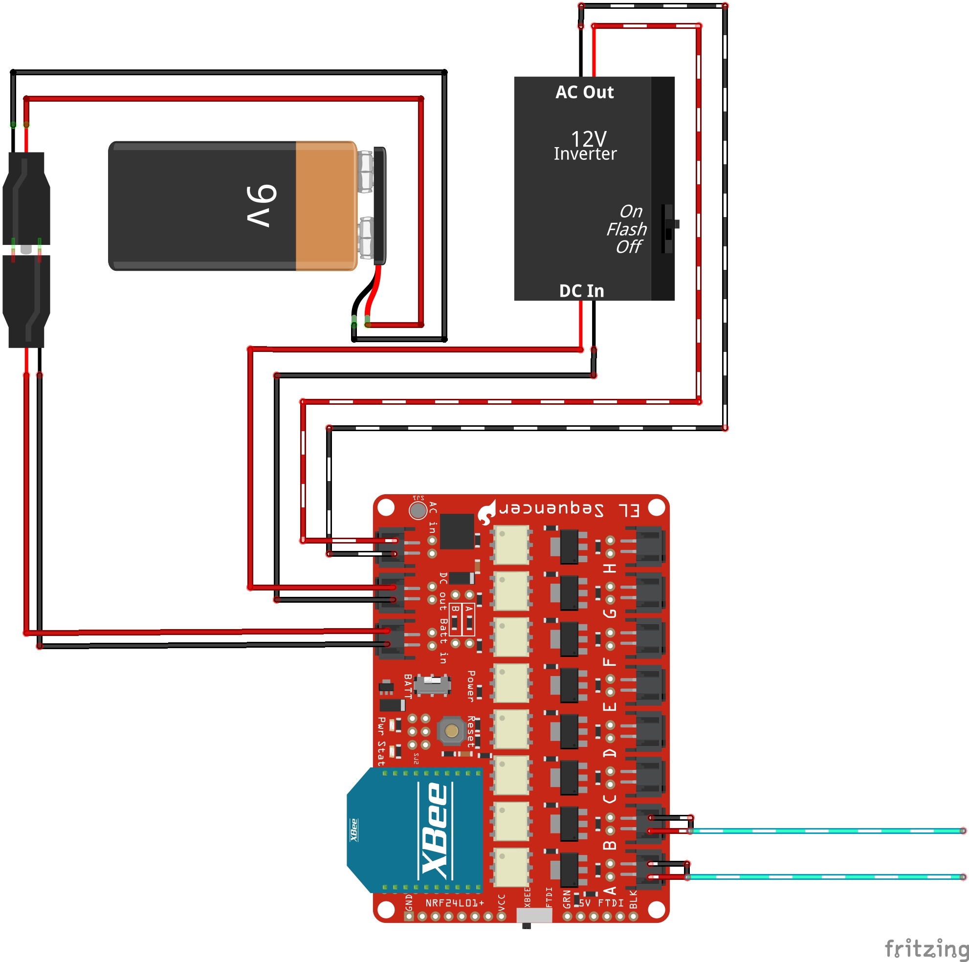
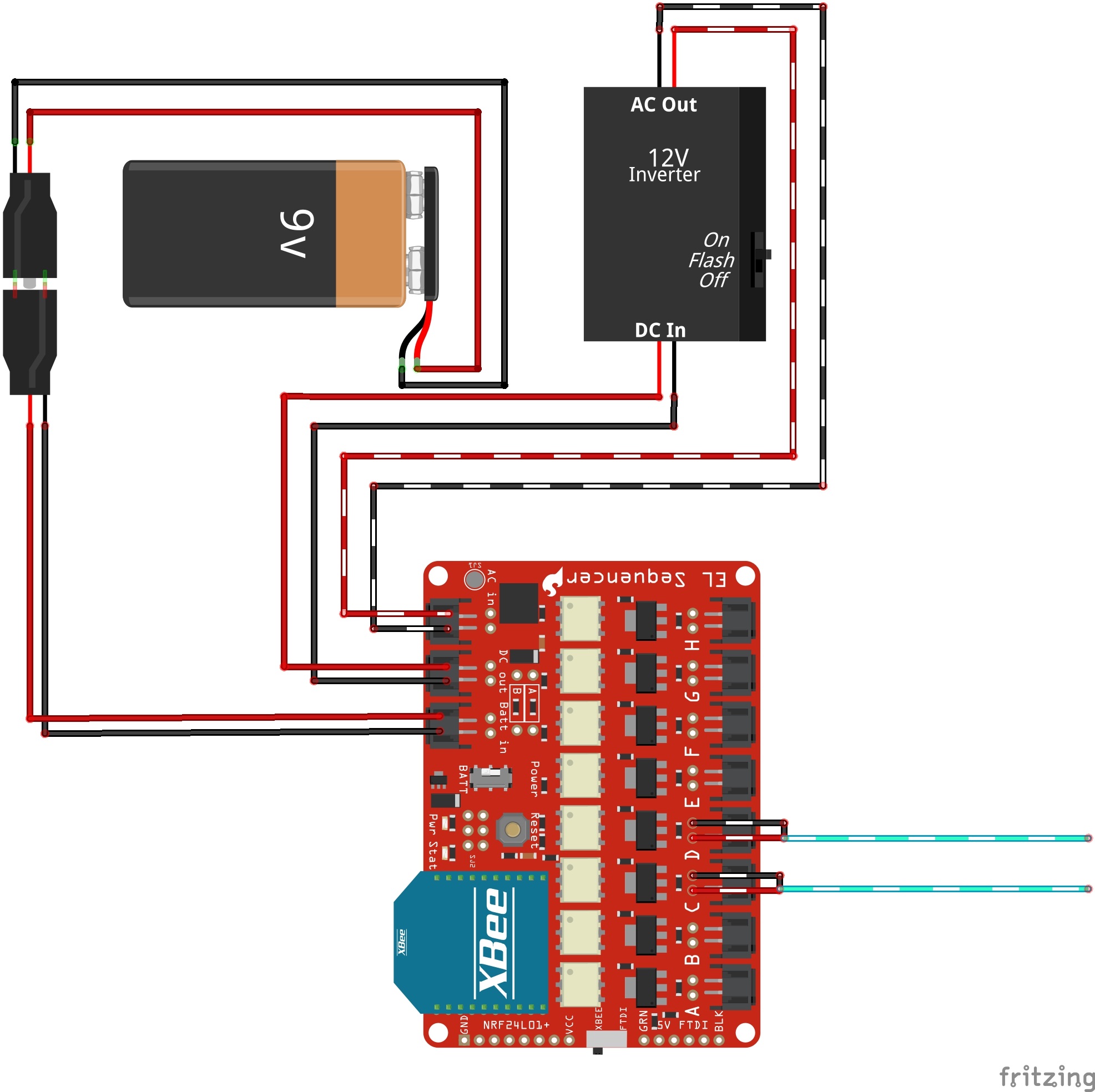
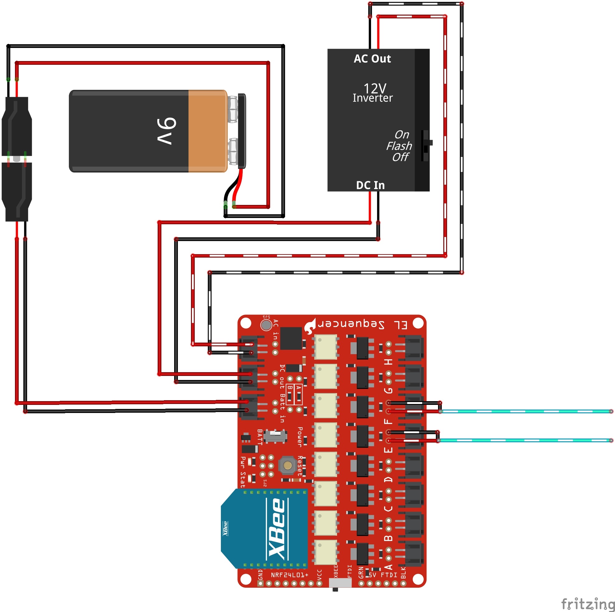
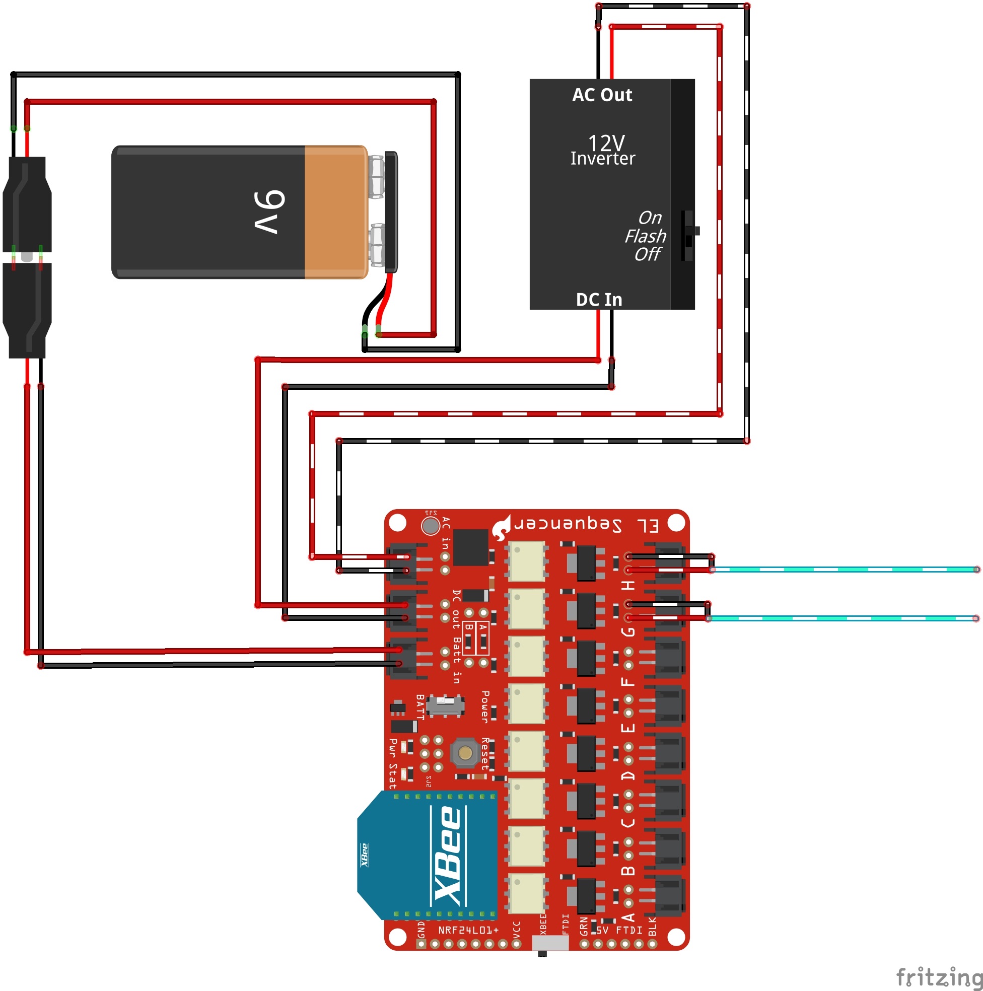
Since the EL Sequencer was using the 12V inverter, a solder jumper was added to SJ1. A 9V battery was as sufficient to power the "12V" inverter, XBee, and EL Sequencer. For simplicity, each dancer had one 3M EL Wire attached to the hoodie and and another 3M for the pants. The only difference was the connection in the EL Wire channel. Each student was paired together to have the same two channels.
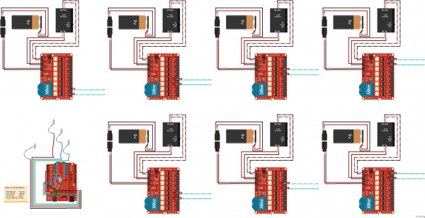
Full
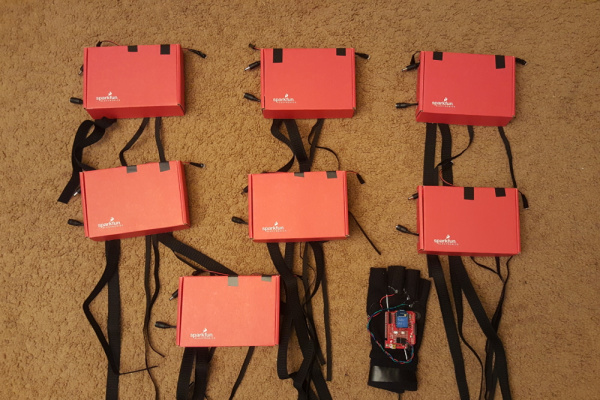
Here's a quick top view of the wireless controller and each remote EL Sequencer.
Securing the Electronics
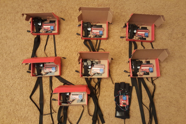
For simplicity, a SparkFun cardboard box was chosen. While it was bulky and not the most comfortable, it was sufficient for the project to hold, protect, and secure the electronics. Using a cardboard box also made it easy to quickly prototype the enclosure.
Two rectangular square holes were cut on the side facing the dancer to easily connect/disconnect the power with the 9V battery. Along the length of a box, holes were cut for easy access to the inverter's switch and all channels of the EL Sequencer. Additional slots on the underside of the enclosure (facing the dancer) were cut to attach strips of elastic to easily remove the enclosure. A screw driver was used to poke holes for each of the EL Sequencer's mounting holes and standoffs. Electrical tape was used to hold down the inverter, 9V battery, and extension cables against the box. Each enclosure was then labeled for each XBee node and dancer.
Configuring XBees
The XBee Series 3 (configured to Series 1) has not been fully tested with the EL Sequencers. Make sure to test it with a pair of XBee 3's on the EL Sequencer before building the suits and using more than one EL Sequencer. You may need to modify the EL Sequencer to get the board working wirelessly with the new XBee 3 modules.
To wirelessly control the suits, I decided to use the XBee Series 1 modules. If you have not already, check out the Starting with XCTU section under Exploring XBees and XCTU to configure your XBees.
Exploring XBees and XCTU
The CH, ID, and DH were set to the same values for all the XBee modules. For the broadcasting XBee (i.e. your controller), the DL was set to FFFF. The receiving XBees on each of the dancers point are set to the MY address of the broadcasting XBee. Each of the XBees had a unique MY address.
| Setting | Acronym | Tx XBee Node 1 (Glove Controller) | Rx XBee Node 2 (Dancer 1) | Rx XBee Node 3 (Dancer 2) | Rx XBee Node 4 (Dancer 3) | Rx XBee Node 5 (Dancer 4) | Rx XBee Node 6 (Dancer 5) | Rx XBee Node 7 (Dancer 6) | Rx XBee Node 8 (Dancer 7) |
|---|---|---|---|---|---|---|---|---|---|
| Channel | CH | C | C | C | C | C | C | C | C |
| PAN ID | ID | 3333 | 3333 | 3333 | 3333 | 3333 | 3333 | 3333 | 3333 |
| Destination Address High | DH | 0 | 0 | 0 | 0 | 0 | 0 | 0 | 0 |
| Destination Address Low | DL | FFFF | 1 | 1 | 1 | 1 | 1 | 1 | 1 |
| 16-bit Source Address | MY | 1 | 2 | 3 | 4 | 5 | 6 | 7 | 8 |
Hardware Hookup
After following the circuit diagrams and enclosure for each dancer, you would simply need to attach the enclosure to the dancer's left hip and leg. If you were following along, the EL wire's connectors from the hoodie and pants should be on the left side of the dancer so that it would be as close to the enclosure as possible. Each dancer's body was different so custom extension cables were used to easily connect.
How to Make a Custom EL Wire Extension Cable
Basic Example Code
For a sanity check when I started writing the code, I had the code turn off two channels to ensure that the code was receiving a character. To follow along, check out the GitHub repository for the project here:
Transmitting Glove Controller
You'll need to upload code to send characters out to the EL Sequencers. With the XBee Series 1 configured to broadcast, you would simply send a character out using a UART. In this case, the glove that was built used software serial pins. If the send button is pressed, a character will be broadcasted out. You'll notice that there is additional code to prevent the controller from sending out a character when the button is constantly being pressed down and for debouncing. This code is the simplest in terms of controlling all the channels.
If you have not already, unzip the GitHub repo and open the example code called XBee_ControllerV1.ino. The path of the example code will probably look similar to: ...\Wireless_Controlled_EL_Dance_Suit\Arduino\XBee_Controller\XBee_ControllerV1. You can also copy the code below and paste it into the Arduino IDE. Select the board (in this case the Arduino/Genuino Uno) and COM port that the board enumerated to. Make sure the switch is flipped to the DLINE before hitting the upload button.
language:c
/*******************************************************************
XBee_ELSequencer_ControllerV1.ino
Modified by Ho Yun Bobby Chan @  SparkFun Electronics May 10th, 2017

Taken from SparkFun XBee EL Sequencer Controller Example
Ho Yun Bobby Chan @ SparkFun Electronics June 20, 2014
Updated by Toni Klopfenstein @ SparkFun Electronics April, 2015
https://github.com/sparkfun/EL_Sequencer

Description:
This is a basic test of the wireless controller to control an EL Sequencer.
The wireless controller consists of an RedBoard Programmed with Arduino, XBee Shield,
XBee Series 1 transceiver, and LED Push Button. The EL Sequencer
uses an EL wire, 12V EL inverter, a 9V wall wart, 9V adapter, XBee female sockets soldered,
battery, and a XBee Series 1 transceiver. An XBee Series 2
can be used but the throughput of the Series 1 is much higher. To
reduce latency, I recommend using the XBee Series 1. The basic
configuration of the XBee module with point-to-point configuratin is
based on Digi's Example tutorial
=> http://examples.digi.com/get-started/basic-xbee-802-15-4-chat/ .
Page 5 of the tutorial shows you how to broadcast with
point-to-multipoint configuration so that multiple EL Sequencers
can be controlled.

Connect the XBee Shield to the Arduino with the switch flipped to the
software serial side labelled "DLINE".

By pushing the button, a character is sent from a remote microcontroller.
The corresponding EL Sequencer will receive the character and control
the EL component on a channel that is associated with that character.
A LED push button was used but not necessary for this to operate. A
normal momentary push button can be used.

Connect momentary LED tactile push buttons to Arduino:
     C = pin 13, the cathode (+) of the LED
     A = GND, the anode (-) of the LED
     B1 = GND
     B2 = pin 8

Using a RedBoard Programmed with Arduino, the XBee transceiver is connected to the
Software Serial pins. By pushing the button, the Arduino will
send one character through the XBee. Logic is used to control
how many characters are sent with the push button. The Arduino
will not send another character until the button is pressed again.

Note: This section of the code can be optimized. As the user is not
pressing down on the button, logic can be added so that the XBee is
not continuously sending serial characters to the receiving
EL Sequencer when idle.

Development environment specifics:
Arduino 1.6.5

This code is beerware; if you see me (or any other SparkFun employee) at the local,
and you've found our code helpful, please buy us a round!
Distributed as-is; no warranty is given.
**************************************************************************/

#include <SoftwareSerial.h>

SoftwareSerial xbee(2, 3); //Rx = 2, Tx = 3

//Declare variables and pin definitions

//Send
const int button1Pin = 8; //push button
const int ledPin1 = 13;  //LED on the push button
//variables to check for button1 state
boolean prev_button1State = false;
boolean current_button1State = false;

/*******************Setup Loop***************************/
void setup() {

  //Declare pin modes
  pinMode(button1Pin, INPUT_PULLUP); //use internal pullup resistor with LED
  pinMode (ledPin1, OUTPUT);//LED to indicate when character has been sent

  //Declare serial connections for debugging
  Serial.begin(9600);
  Serial.println("Arduino started sending bytes via XBee");

  xbee.begin(9600);
  Serial.println("EL Sequencer Controller's XBee Ready to Communicate");
}

/*******************Main Loop***************************/
void loop() {
  //initialize variables to read buttons
  int button1State;

  button1State = digitalRead(button1Pin);
  /***button1state
   - LOW or 0 means pressed
   - HIGH or 1 means not pressed
   ****/

  //if button is pressed, it will be pulled low
  if (button1State == LOW) {
    digitalWrite(ledPin1, HIGH); //turn push button LED ON
    current_button1State = true; // button has been pressed once

    if (prev_button1State != current_button1State) //check to see if button is still being pressed
    {
      Serial.println("Button is pressed.");
      xbee.write("A");//Tell Sequencer to change to mode by sending a character
    }
    else {
      //do nothing because finger is still on button
    }
    prev_button1State = current_button1State;
  }

  //button has not been pressed, it will be high again
  else {
    current_button1State = false;
    digitalWrite(ledPin1, LOW); // turn push button LED OFF

    prev_button1State = current_button1State;
  }

}
Receiving EL Sequencer Blink Code
You'll also need to uploade code to receive the characters for each EL Sequencer. You will need another UART to connect to the XBee Series 1 configured to receive characters from the broadcasting XBee. In this case, the EL Sequencer was designed to connect the ATmega328P's hardware UART to the XBee Series 1's UART. Therefore, the Serial was used instead of SoftwareSerial.
Open the example code called XBee_ELSequencerV1.ino. The path of the example code will probably look similar to: ...\Wireless_Controlled_EL_Dance_Suit\Arduino\XBee_ELSequencer\XBee_ELSequencerV1. You can also copy the code below and paste it into the Arduino IDE. Select the board (in this case the Arduino Pro or Pro Mini, ATmega328P (3.3V, 8MHz) but it can also be LilyPad Arduino) and COM port that the USB-to-Serial Converter enumerated to. Hit the upload button.
language:c
    /**********************************************************************
XBee_ELSequencerV1.ino
Created by Ho Yun Bobby Chan @  SparkFun Electronics May 10th, 2017

 * Taken from SparkFun XBee EL Sequencer Demo Sketch
 * Ho Yun Bobby Chan @ SparkFun Electronics June 20, 2014
 * Updated by Toni Klopfenstein @ SparkFun Electronics April, 2015
 * https://github.com/sparkfun/EL_Sequencer
 *
 * Description:
 * This is a basic test of the EL Sequencer to control an EL Sequencer
 * The wireless controller consists of an RedBoard Programmed with Arduino, XBee Shield,
 * XBee Series 1 transceiver, and LED Push Button. The EL Sequencer
 * uses an EL wire, 12V EL inverter, a 9V wall wart, 9V adapter, XBee female sockets soldered,
 * battery, and a XBee Series 1 transceiver. An XBee Series 2
 * can be used but the throughput of the Series 1 is much higher. To
 * reduce latency, I recommend using the XBee Series 1. The basic
 * configuration of the XBee module with point-to-point configuratin is
 * based on Digi's Example tutorial
 * => http://examples.digi.com/get-started/basic-xbee-802-15-4-chat/ .
 * Page 5 of the tutorial shows you how to broadcast with
 * point-to-multipoint configuration so that multiple EL Sequencers
 * can be controlled.
 *
 * By pushing the button, a character is sent from a remote microcontroller.
 * The corresponding EL Sequencer will receive the character and control
 * the EL component on a channel that is associated with that character.
 *
 * EL Sequencer uses the hardware UART of the Atmega328 for communication:
 * pin 0 = Rx
 * pin 1 = Tx
 *
 * Note: Make sure to remove the XBee Series 1 on the EL Sequencer when
 * uploading a new sketch file otherwise it will brick the XBee. You can
 * always use the next generation XCTU software to unbrick and recover
 * the transceiver.
 *
 * Development environment specifics:
 * Arduino 1.6.3
 *
 * This code is beerware; if you see me (or any other SparkFun employee) at the local,
 * and you've found our code helpful, please buy us a round!
 * Distributed as-is; no warranty is given.
 *
 ***********************************************************************/

//Declare character 'val'
char val;

//LED to check if the LED is initialized.
const int status_LED = 13;

/*******************Setup Loop***************************/
void setup() {
  Serial.begin(9600); //Begin Serial communication for debugging
  Serial.println("EL Sequencer's XBee is Ready to Receive Characters");

  val = 'A';// button pressed, therefore sending  letter A

  //Initialize pins
  pinMode(status_LED, OUTPUT); //Set pin mode as output for status LED
  pinMode(2, OUTPUT); //Set pin mode as output for Channel A
  pinMode(3, OUTPUT); //Set pin mode as output for Channel B
  pinMode(4, OUTPUT); //Set pin mode as output for Channel C
  pinMode(5, OUTPUT); //Set pin mode as output for Channel D
  pinMode(6, OUTPUT); //Set pin mode as output for Channel E
  pinMode(7, OUTPUT); //Set pin mode as output for Channel F
  pinMode(8, OUTPUT); //Set pin mode as output for Channel G
  pinMode(9, OUTPUT); //Set pin mode as output for Channel H

  //Status LED to see if the EL Sequencer is initializing
  for (int i = 0; i < 3; i++) {
    digitalWrite(status_LED, HIGH);//set Status LED on
    delay(50);
    digitalWrite(status_LED, LOW); //set Status LED off
    delay(50);
  }

  digitalWrite(2, HIGH); //Channel A
  digitalWrite(3, HIGH); //Channel B

  digitalWrite(4, LOW); //Channel C
  digitalWrite(5, LOW); //Channel D

  digitalWrite(6, LOW); //Channel E
  digitalWrite(7, LOW); //Channel F

  digitalWrite(8, LOW); //Channel G
  digitalWrite(9, LOW); //Channel H

  delay(1000); //Wait 1 second
}

/*******************Main Loop***************************/
void loop() {

  //Check if XBee is receiving data from other XBee
  if (Serial.available()) {
    val = Serial.read();

    //Check to see if character sent is letter A
    if (val == 'A') {
      digitalWrite(status_LED, LOW); //turn ON Status LED
      digitalWrite(2, LOW); //Channel A
      digitalWrite(3, LOW); //Channel B
      delay(1000);
      Serial.println("Character Received");
    }

    else {
      //rewrote controller code to stop constantly sending Z
      //toggled pins outside of this nested condition statement
    }
  }

  digitalWrite(status_LED, HIGH); //turn OFF Status LED

  digitalWrite(2, HIGH); //Channel A
  delay(50);
  digitalWrite(3, HIGH); //Channel B
}
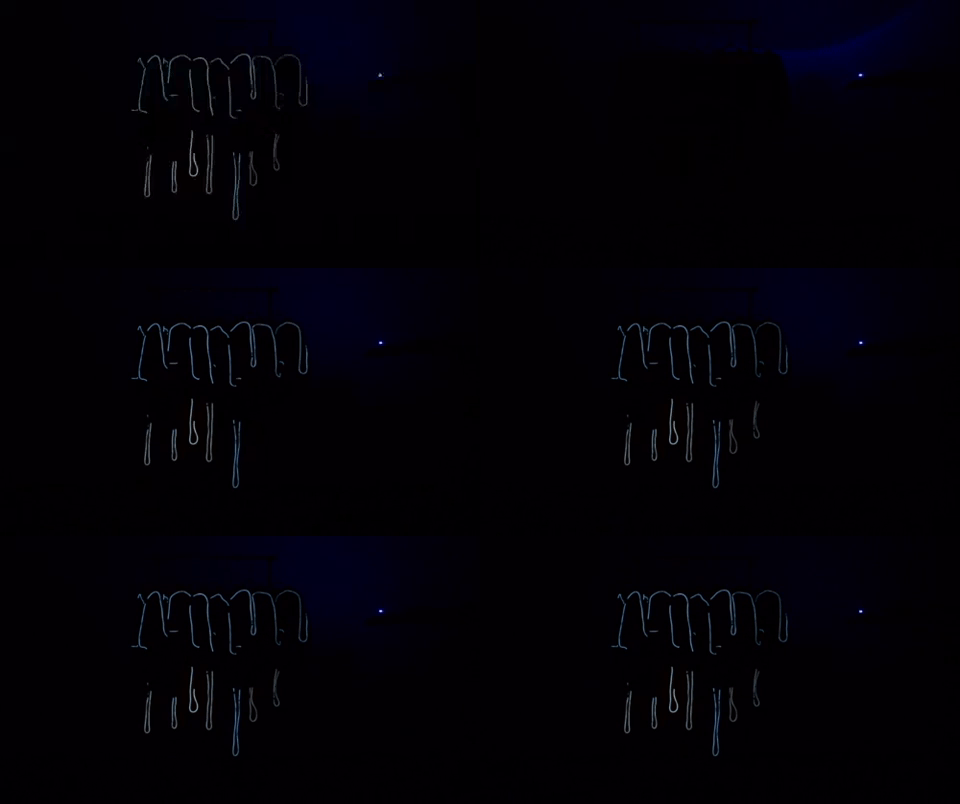
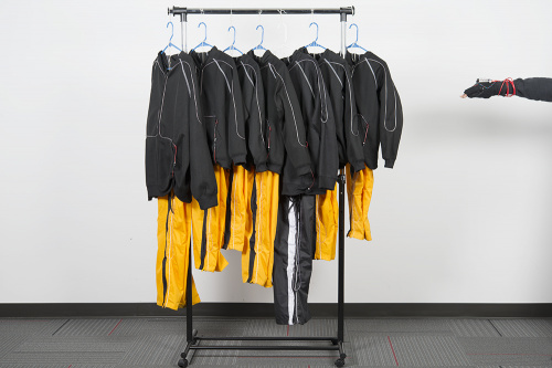
When finished, you should see the EL Sequencer blink two EL wires connected to the channels when pressing the send button. You probably won't see the EL too well in a well lit room. Below is an image of all the EL Wire hoodies angled with the side of each pair of ppants when the room lights are turned on.
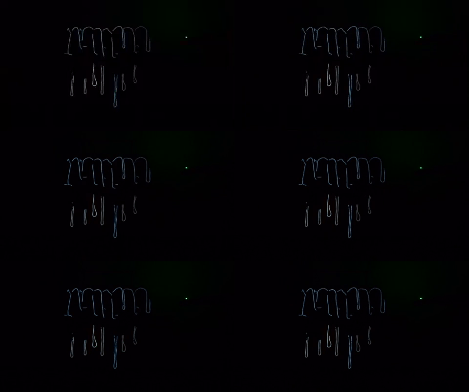
Turning off the lights, you should see the channels blink clearly.
Custom Example Code
Listening and Adjusting w/ Audacity
To sync the animation with the music, I had to listen to the music several times just as if I was choreographing moves for a piece. You can also use Audacity or a DJ application visualize the length of the beats. For simplicity, I decided to have three sections over the course of a few counts where the EL Wire suits would animate with the music. With some experimenting and fine tuning the delays, I was able to sync the animation with the music.
Based on the way that I wrote the code with the XBees, I noticed that there were two limitations when syncing the animation with the music. The first limitation that I had to press the send button while also in the correct mode as I was moving. This was quite tricky. The second limitation was that once the sequence began, there was really no way to change the animation until the sequence was finished. Longer sequences and delays made it harder to control which was why I decided to have a three sections over a few counts. I would have had to tediously write more code and test to sync the animations with the music.
Glove Controller Example Code
If you have not already, unzip the GitHub repo and open the example code called XBee_ControllerV3.ino. V2 was a work in progress in case I accidentally broke the code. V3 was the final code that was used for the performance. The path of the example code will probably look similar to: ...\Wireless_Controlled_EL_Dance_Suit\Arduino\XBee_Controller\XBee_ControllerV3. You can also copy the code below and paste it into the Arduino IDE. Select the board (in this case the Arduino/Genuino Uno) and COM port that the board enumerated to. Make sure the switch is flipped to the DLINE before hitting the upload button.
language:c
/*******************************************************************
XBee_ELSequencer_ControllerV3.ino
Created by Ho Yun Bobby Chan @  SparkFun Electronics May 12th, 2017

Taken from SparkFun XBee EL Sequencer Controller
Ho Yun Bobby Chan @ SparkFun Electronics June 20, 2014
Updated by Toni Klopfenstein @ SparkFun Electronics April, 2015
https://github.com/sparkfun/EL_Sequencer

Description:
This is a sketch for the wireless controller used to control 7x EL dance suits.
The wireless controller consists of a RedBoard Programmed with Arduino,
XBee Shield, XBee Series 1 transceiver, diffused RGB Common Cathode LED,
Blue Clear LED, 330Ohm current limiting resistors, a button, 9V battery,
and a 9V adapter.

Each of the 7x EL dance suits contain an EL Sequencer, 2x EL Wires, a
12V EL inverter, XBee female sockets soldered, a 9V battery, 9V adapter,
and a XBee Series 1 transceiver.  An XBee Series 2 can be used but the throughput
of the Series 1 is much higher. To reduce latency, I recommend using the XBee
Series 1. The basic configuration of the XBee module with point-to-point configuratin is
based on Digi's Example tutorial => https://www.digi.com/blog/xbee/basic-xbee-802-15-4-chat/.
page 5 of the tutorial shows you how to broadcast with
point-to-multipoint configuration so that multiple EL Sequencers
can be controlled.

Connect the XBee Shield to the Arduino with the switch flipped to the
software serial side labeled "DLINE".

By pushing the button, a character is sent from a remote microcontroller.
The corresponding EL Sequencer will receive the character and control
the EL component on a channel that is associated with that character.

Using a RedBoard programmed with Arduino, the XBee transceiver is connected to the
Software Serial pins. By pushing the button, the Arduino will
send one character through the XBee. Logic is used to control
how many characters are sent with the push button. The Arduino
will not send another character until the button is pressed again.

Note: This section of the code can be optimized. As the user is not
pressing down on the button, logic can be added so that the XBee is
not continuously sending serial characters to the receiving
EL Sequencer when idle.

Development environment specifics:
Arduino 1.6.5

This code is beerware; if you see me (or any other SparkFun employee) at the local,
and you've found our code helpful, please buy us a round!
Distributed as-is; no warranty is given.
**************************************************************************/

#include <SoftwareSerial.h>

SoftwareSerial xbee(2, 3); //Rx = 2, Tx = 3

//Declare variables and pin definitions

char send_CHAR = 'A'; //default send character

int pattern = 0; //pattern that we are going to send

//SEND Button
const int button1Pin = 4; //push button
const int ledPin1 = 13;  //LED to indicate when a character has been sent
//variables to check for button1 state
boolean prev_button1State = false;
boolean current_button1State = false;

//LED Status Indicator
int ledR = 5; //hardware PWM
int ledG = 6; //hardware PWM
int ledB = 9; //hardware PWM

//UP Button
const int button2Pin = 11; //push button to move ahead to next sequence
//variables to check for button2 state
boolean prev_button2State = false;
boolean current_button2State = false;

//DOWN Button
const int button3Pin = 12;//push button to move back a sequence
//variables to check for button3 state
boolean prev_button3State = false;
boolean current_button3State = false;

/*******************Setup Loop***************************/
void setup() {
  //Declare buttons and status LEDs

  pinMode (ledPin1, OUTPUT); //send LED
  pinMode(button1Pin, INPUT_PULLUP); //SEND button, use internal pullup resistor

  // initialize the digital pins as an output for status LED
  pinMode(ledR, OUTPUT);
  pinMode(ledG, OUTPUT);
  pinMode(ledB, OUTPUT);
  pinMode(button2Pin, INPUT_PULLUP); //UP button, use internal pullup resistor
  pinMode(button3Pin, INPUT_PULLUP); //DOWN button, use internal pullup resistor

  //Declare serial connections for debugging
  Serial.begin(9600);
  Serial.println("Arduino started sending bytes via XBee");

  //Declare software serial conenction with XBee
  xbee.begin(9600);
  Serial.println("EL Sequencer Controller's XBee Ready to Communicate");

  sequenceTest();//visually initialization to see that we have finished initializing
}

/*******************Main Loop***************************/
void loop() {
  //initialize variables to read buttons
  int button1State;
  int button2State;
  int button3State;

  button1State = digitalRead(button1Pin);
  button2State = digitalRead(button2Pin);
  button3State = digitalRead(button3Pin);
  /*buttonXstate
   - LOW or 0 means pressed
   - HIGH or 1 means not pressed
   */

  //-----------Check If SENT Button Has Been Pressed----------
  //if SENT button is pressed, it will be pulled low
  if (button1State == LOW) {
    digitalWrite(ledPin1, HIGH); //turn LED indicating if a character has been sent ON
    current_button1State = true; // button has been pressed once

    if (prev_button1State != current_button1State) //check to see if button is still being pressed
    {
      Serial.println("Button is pressed.");
      xbee.write(send_CHAR);//Tell Sequencer to change mode
    }
    else {
      //do nothing because finger is still on button
    }
    prev_button1State = current_button1State;
  }

  //sent button has not been pressed, it will be high again
  else {
    current_button1State = false;
    digitalWrite(ledPin1, LOW); // turn push button LED OFF

    prev_button1State = current_button1State;
  }//-----------End Check for SENT Button----------

  //-----------Check If UP Button Has Been Pressed----------
  if (button2State == LOW) {
    current_button2State = true; //UP button has been pressed once

    if (prev_button2State != current_button2State) { //check to see if button is still being pressed
      pattern = pattern + 1; //change LED pattern after button has been pressed
      if (pattern < 0 || pattern > 5) {
        //reset pattern
        pattern = 0;
      }

    }
    else { //do nothing because finger is still on button
    }
    prev_button2State = current_button2State;
  }
  //UP button has not been pressed, it will be high
  else {
    current_button2State = false;
    prev_button2State = current_button2State;
  }//-----------End Check for Up Button----------

  //-----------Check If DOWN Button Has Been Pressed----------
  if (button3State == LOW) {
    current_button3State = true; //button has been pressed once

    if (prev_button3State != current_button3State) { //check to see if button is still being pressed
      pattern = pattern - 1; //change LED pattern after button has been pressed
      if (pattern < 0 || pattern > 5) {
        //reset pattern
        pattern = 5;
      }
    }
    else { //do nothing because finger is still on button
    }
    prev_button3State = current_button3State;
  }
  //button has not been pressed, it will be high
  else {
    current_button3State = false;
    prev_button3State = current_button3State;
  }//-----------End Check for DOWN Button----------

  delay(50);

  //save send character into variable depending on button press and change status LED
  switch (pattern) {
    case 1:
      greenON();
      send_CHAR = 'B';
      break;
    case 2:
      blueON();
      send_CHAR = 'C';
      break;
    case 3:
      allOFF();//blink status LED
      delay(50);
      blueON();
      delay(50);
      send_CHAR = 'D';
      break;
    case 4:
      blueON();
      send_CHAR = 'E';
      break;
    default:
      redON();
      send_CHAR = 'A';
      break;
  }

}//end loop


/*Below are the modular functions for changing the color of a RGB LED.
 This will be used to help identify what mode we are currently in:
 ROYGBIV
 Note: A 9V battery is not able to fully power all three LEDs simultaneously...
 MODE
 1.) red              = red[HIGH]
 .) tangerine orange = red[HIGH]+ green[50]
 2.) yellow           = red[HIGH]+ green[HIGH]
 3.) green            =          + green[HIGH]
 4.) clear blue       =          + green[HIGH] + blue[HIGH]
 5.) blue             =                        + blue[HIGH]
 6.) magenta          = red[HIGH]+             + blue[HIGH]
 .) white            = red[HIGH]+ green[HIGH] + blue[HIGH]
 */

void allOFF() {
  analogWrite(ledR, 0);
  analogWrite(ledG, 0);
  analogWrite(ledB, 0);
}

void redON() { //Seq 1
  analogWrite(ledR, 255);
  analogWrite(ledG, 0);
  analogWrite(ledB, 0);
}

void greenON() { //Seq 2
  analogWrite(ledR, 0);
  analogWrite(ledG, 255);
  analogWrite(ledB, 0);
}

void blueON() { //Seq 3
  analogWrite(ledR, 0);
  analogWrite(ledG, 0);
  analogWrite(ledB, 255);
}

void yellowON() {
  analogWrite(ledR, 255);
  analogWrite(ledG, 255);
  analogWrite(ledB, 0);
}

void clearblueON() {
  analogWrite(ledR, 0);
  analogWrite(ledG, 255);
  analogWrite(ledB, 255);
}

void magentaON() {
  analogWrite(ledR, 255);
  analogWrite(ledG, 0);
  analogWrite(ledB, 255);
}

void sequenceTest() {
  redON();
  delay(50);
  allOFF();
  delay(50);

  yellowON();
  delay(50);
  allOFF();
  delay(50);

  greenON();
  delay(50);
  allOFF();
  delay(50);

  clearblueON();
  delay(50);
  allOFF();
  delay(50);

  blueON();
  delay(50);
  allOFF();
  delay(50);

  magentaON();
  delay(50);
  allOFF();
  delay(50);

  //whiteON();//white drains too much power from a 9V, commenting out.
  //delay(50);
  //allOFF();
  //delay(50);

}
EL Sequencers Example Code
Open the example code called XBee_ELSequencerV3.ino. The path of the example code will probably look similar to: ...\Wireless_Controlled_EL_Dance_Suit\Arduino\XBee_ELSequencer\XBee_ELSequencerV3. You can also copy the code below and paste it into the Arduino IDE. Select the board (in this case the Arduino Pro or Pro Mini, ATmega328P (3.3V, 8MHz) but it can also be LilyPad Arduino) and COM port that the USB-to-Serial Converter enumerated to. Hit the upload button.
language:c
/**********************************************************************
  XBee_ELSequencerV3.ino
  Modified by Ho Yun Bobby Chan @  SparkFun Electronics May 12th, 2017

   Taken from the SparkFun XBee EL Sequencer Demo Sketch
   Ho Yun Bobby Chan @ SparkFun Electronics June 20, 2014
   Updated by Toni Klopfenstein @ SparkFun Electronics April, 2015
   https://github.com/sparkfun/EL_Sequencer

   Description:
   This is a modified sketch for the EL Sequencer with a wireless controller.
   The wireless controller consists of a RedBoard Programmed with Arduino,
   XBee Explorer, XBee Series 1 transceiver, diffused RGB Common Cathode LED,
   Blue Clear LED, 330Ohm current limiting resistors, 3x buttons,
   a 9V battery, and a 9V adapter.

   Each of the 7x EL dance suits contain an EL Sequencer, 2x EL Wires, a
   12V EL inverter, XBee female sockets soldered, a 9V battery, 9V adapter,
   and a XBee Series 1 transceiver.  An XBee Series 2 can be used but the throughput
   of the Series 1 is much higher. To reduce latency, I recommend using the XBee
   Series 1. The basic configuration of the XBee module with point-to-point configuratin is
   based on Digi's Example tutorial => https://www.digi.com/blog/xbee/basic-xbee-802-15-4-chat/.
   Page 5 of the tutorial shows you how to broadcast with
   point-to-multipoint configuration so that multiple EL Sequencers
   can be controlled.

   By pushing the button, a character is sent from a remote microcontroller.
   The corresponding EL Sequencer will receive the character and control
   the EL component on a channel that is associated with that character.

   EL Sequencer uses the hardware UART of the Atmega328 for communication:
   pin 0 = Rx
   pin 1 = Tx

   Note: Make sure to remove the XBee Series 1 on the EL Sequencer when
   uploading a new sketch file otherwise it will brick the XBee. You can
   always use the next generation XCTU software to unbrick and recover
   the transceiver.

   Development environment specifics:
   Arduino 1.6.5

   This code is beerware; if you see me (or any other SparkFun employee) at the local,
   and you've found our code helpful, please buy us a round!
   Distributed as-is; no warranty is given.

 ***********************************************************************/

char val; //Declare character 'val' when Peripheral XBee receives a character
char temp_delete; //used to delete buffer and prevent false triggers when Controller XBee sends character more than once

//LED to check if the LED is initialized.
const int status_LED = 13;

int counter = 0; //adding counter to prevent false triggers for a small period of time
boolean XBee_sent = false; //flag to see if we have received any characters after a certain period of time

/*******************Setup Loop***************************/
void setup() {
  Serial.begin(9600); //Begin Serial communication and debugging
  Serial.println("EL Sequencer's XBee is Ready to Receive Characters");

  val = 'A'; //save as default character

  //Initialize pins
  pinMode(status_LED, OUTPUT); //Set pin mode as output for status LED
  pinMode(2, OUTPUT); //Set pin mode as output for Channel A
  pinMode(3, OUTPUT); //Set pin mode as output for Channel B
  pinMode(4, OUTPUT); //Set pin mode as output for Channel C
  pinMode(5, OUTPUT); //Set pin mode as output for Channel D
  pinMode(6, OUTPUT); //Set pin mode as output for Channel E
  pinMode(7, OUTPUT); //Set pin mode as output for Channel F
  pinMode(8, OUTPUT); //Set pin mode as output for Channel G
  pinMode(9, OUTPUT); //Set pin mode as output for Channel H

  //Status LED to see if the EL Sequencer is initializing
  for (int i = 0; i < 3; ++i) {
    digitalWrite(status_LED, HIGH);//set Status LED on
    delay(50);
    digitalWrite(status_LED, LOW); //set Status LED off
    delay(50);
  }

  all_ON();//turn on all EL channels

  delay(100); //Wait a little
}

/*******************Main Loop***************************/
void loop() {
  if (XBee_sent == false) {
    //we have not received a character yet after a certain period of time, we can see if the Controller XBee has sent any characters
    if (Serial.available()) {
      //check if peripheral XBee is receiving data from controller XBee
      val = Serial.read();//save whatever is in the buffer to the variable
      counter = 0;        //set counter to 0 to prevent false button presses
      XBee_sent = true;   //we have received a character

      //if debugging, we can see what character is recevied
      Serial.print("Character Received = ");
      Serial.println(val);

      //Check to see if character sent is any of the recognized characters and jump to the sequence
      if (val == 'A') {
        Seq_0();
      }
      else if (val == 'B') {
        Seq_1();
      }
      else if (val == 'C') {
        Seq_2();
      }
      else if (val == 'D') {
        Seq_3();
      }
      else if (val == 'E') {
        Seq_4();
      }

    }//end buffer check
  }//end check to see if we have not received a character after a certain period of time

  if (counter >= 10) {//this section of code will reset the flag "XBee_Sent" so we can begin listening for characters again
    if (XBee_sent == true) {
      Serial.println("Counter = 10, we are ready to receive characters again");
    }
    XBee_sent = false;
  }

  if (XBee_sent == true) {//this section of code is used as a delay to prevent false button presses
    counter = ++counter;//keep adding until we reach 10, then we can reset flag and begin receiving again

    //if connected to a computer, check to see the duration of the delay
    Serial.print("Counter = ");
    Serial.println(counter);

    temp_delete = Serial.read();//try to clear false triggers in buffer provided by Controller XBee until counter resets
  }

}//end loop()

//**********MODULAR SEQUENCED FUNCTIONS**********

void all_ON() {
  //this function is used to turn all channels ON
  //Bobby
  digitalWrite(2, HIGH); //Channel A, hoodie
  digitalWrite(3, HIGH); //Channel B, pants
  //Antuan, Kaden
  digitalWrite(4, HIGH); //Channel C, hoodie
  digitalWrite(5, HIGH); //Channel D, pants
  //Mireku, Talon
  digitalWrite(6, HIGH); //Channel E, hoodie
  digitalWrite(7, HIGH); //Channel F, pants
  //Madi, Henry
  digitalWrite(8, HIGH); //Channel G, hoodie
  digitalWrite(9, HIGH); //Channel H, pants
}


void all_OFF() {
  //this function is used to turn all channels OFF
  //Bobby
  digitalWrite(2, LOW); //Channel A, hoodie
  digitalWrite(3, LOW); //Channel B, pants
  //Antuan, Kaden
  digitalWrite(4, LOW); //Channel C, hoodie
  digitalWrite(5, LOW); //Channel D, pants
  //Mireku, Talon
  digitalWrite(6, LOW); //Channel E, hoodie
  digitalWrite(7, LOW); //Channel F, pants
  //Madi, Henry
  digitalWrite(8, LOW); //Channel G, hoodie
  digitalWrite(9, LOW); //Channel H, pants
}

void Seq_0() {
  //function used to flash Bobby's suit with the beat at 5 seconds into the edited C2C track

  digitalWrite(status_LED, LOW); //turn OFF Status LED
  digitalWrite(2, LOW); //Channel A
  digitalWrite(3, LOW); //Channel B
  delay(500);

  digitalWrite(status_LED, HIGH); //turn on Status LED

  digitalWrite(2, HIGH); //Channel A
  delay(500);
  digitalWrite(3, HIGH); //Channel B
  delay(500);
  digitalWrite(2, LOW); //Channel A
  digitalWrite(3, LOW); //Channel B
  delay(500);
  digitalWrite(2, HIGH); //Channel A
  digitalWrite(3, HIGH); //Channel B

  delay(500);
  digitalWrite(2, LOW); //Channel A
  digitalWrite(3, LOW); //Channel B
  delay(250);
  digitalWrite(2, HIGH); //Channel A
  digitalWrite(3, HIGH); //Channel B

  delay(500);

  digitalWrite(2, LOW); //Channel A
  digitalWrite(3, LOW); //Channel B
  delay(500);
  digitalWrite(2, HIGH); //Channel A
  digitalWrite(3, HIGH); //Channel B

  delay(250);
  digitalWrite(2, LOW); //Channel A
  digitalWrite(3, LOW); //Channel B
  delay(250);
  digitalWrite(2, HIGH); //Channel A
  digitalWrite(3, HIGH); //Channel B
  delay(250);
  digitalWrite(2, LOW); //Channel A
  digitalWrite(3, LOW); //Channel B
  delay(250);
  digitalWrite(2, HIGH); //Channel A
  digitalWrite(3, HIGH); //Channel B
  delay(250);
  digitalWrite(2, LOW); //Channel A
  digitalWrite(3, LOW); //Channel B
  delay(250);
  digitalWrite(2, HIGH); //Channel A
  digitalWrite(3, HIGH); //Channel B
  delay(250);
  digitalWrite(2, LOW); //Channel A
  digitalWrite(3, LOW); //Channel B
  delay(250);
  digitalWrite(2, HIGH); //Channel A
  digitalWrite(3, HIGH); //Channel B

  all_ON();//turn everything back on
}

void Seq_1() {
  //function used to toggle the channels back & forth and hit the beat at 45 seconds into the edited C2C track

  for (int i = 0; i < 8; ++i) {
    //Bobby
    digitalWrite(2, HIGH); //Channel A, hoodie
    digitalWrite(3, LOW); //Channel B, pants
    //Antuan, Kaden
    digitalWrite(4, HIGH); //Channel C, hoodie
    digitalWrite(5, LOW); //Channel D, pants
    //Mireku, Talon
    digitalWrite(6, LOW); //Channel E, hoodie
    digitalWrite(7, HIGH); //Channel F, pants
    //Madi, Henry
    digitalWrite(8, LOW); //Channel G, hoodie
    digitalWrite(9, HIGH); //Channel H, pants
    delay(250);

    //Bobby
    digitalWrite(2, LOW); //Channel A, hoodie
    digitalWrite(3, HIGH); //Channel B, pants
    //Antuan, Kaden
    digitalWrite(4, LOW); //Channel C, hoodie
    digitalWrite(5, HIGH); //Channel D, pants
    //Mireku, Talon
    digitalWrite(6, HIGH); //Channel E, hoodie
    digitalWrite(7, LOW); //Channel F, pants
    //Madi, Henry
    digitalWrite(8, HIGH); //Channel G, hoodie
    digitalWrite(9, LOW); //Channel H, pants
    delay(250);
  }

  all_ON();
  delay(750);
  all_OFF();
  delay(100);
  all_ON();

}

void Seq_2() {
  //this function turns all the channels ON just in case something happens

  all_ON();
}

void Seq_3() {
  //function used to as a ripple effect and turn on the channels to the beat scratch at 2 minutes 10 seconds into the edited C2C track

  all_OFF();
  delay(100);
  //Madi, Henry
  digitalWrite(8, HIGH); //Channel G, hoodie
  digitalWrite(9, LOW); //Channel H, pants
  delay(100);
  //Antuan, Kaden
  digitalWrite(4, HIGH); //Channel C, hoodie
  digitalWrite(5, LOW); //Channel D, pants
  delay(100);
  //Bobby
  digitalWrite(2, HIGH); //Channel A, hoodie
  digitalWrite(3, LOW); //Channel B, pants

  //Mireku, Talon
  digitalWrite(6, HIGH); //Channel E, hoodie
  digitalWrite(7, LOW); //Channel F, pants
  delay(100);

  //Madi, Henry
  digitalWrite(8, HIGH); //Channel G, hoodie
  digitalWrite(9, HIGH); //Channel H, pants
  delay(100);
  //Antuan, Kaden
  digitalWrite(4, HIGH); //Channel C, hoodie
  digitalWrite(5, HIGH); //Channel D, pants
  delay(100);
  //Bobby
  digitalWrite(2, HIGH); //Channel A, hoodie
  digitalWrite(3, HIGH); //Channel B, pants

  //Mireku, Talon
  digitalWrite(6, HIGH); //Channel E, hoodie
  digitalWrite(7, HIGH); //Channel F, pants
  delay(100);

}

void Seq_4() {
  //this function turns all the channels ON just in case something happens

  all_ON();
}
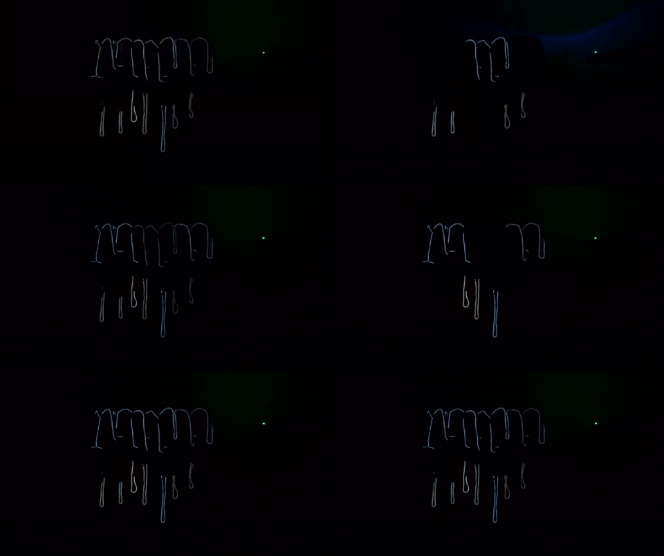
By hitting the send button, the first sequence should animate to the beat from the beginning. By toggling the next mode, the LED should change to indicate that the next mode is ready to be sent. By hitting the send button again, you should see the EL wire attached to the hoodie and pants switching on and off as shown in the GIF below. I had my students in a certain formation when the sequence started.
By toggling the mode again and hitting the button again, the EL wire individually lit up on the hoodies and then the pants as shown in the GIF below.
Template Example Code
While the code was useful for my application, you'll need to write your own code to sync the effects with the music. I made a quick template for an EL Sequencer with a few simple modes to control two channels. The modes will sequence the channels to turn them all on, blink (off-on), turn off, alternate, ripple, and stack (i.e. light up each channel one at a time).
Glove Controller Example Code
The code for the glove controller is the same but with one added condition statement. Feel free to add more depending on your application. Open the example code called XBee_ControllerTemplate.ino. V2 was a work in progress in case I accidentally broke the code. V3 was the final code that was used for the performance. The path of the example code will probably look similar to: ...\Wireless_Controlled_EL_Dance_Suit\Arduino\XBee_Controller\XBee_ControllerTEMPLATE. You can also copy the code below and paste it into the Arduino IDE. Select the board (in this case the Arduino/Genuino Uno) and COM port that the board enumerated to. Make sure the switch is flipped to the DLINE before hitting the upload button.
language:c
/*******************************************************************
XBee_ELSequencer_ControllerTEMPLATE.ino
Created by Ho Yun Bobby Chan @  SparkFun Electronics May 12th, 2017

Taken from SparkFun XBee EL Sequencer Controller
Ho Yun Bobby Chan @ SparkFun Electronics June 20, 2014
Updated by Toni Klopfenstein @ SparkFun Electronics April, 2015
https://github.com/sparkfun/EL_Sequencer

Description:
This is a sketch for the wireless controller used to control 7x EL dance suits.
The wireless controller consists of a RedBoard Programmed with Arduino,
XBee Shield, XBee Series 1 transceiver, diffused RGB Common Cathode LED,
Blue Clear LED, 330Ohm current limiting resistors, a button, 9V battery,
and a 9V adapter.

Each of the 7x EL dance suits contain an EL Sequencer, 2x EL Wires, a
12V EL inverter, XBee female sockets soldered, a 9V battery, 9V adapter,
and a XBee Series 1 transceiver.  An XBee Series 2 can be used but the throughput
of the Series 1 is much higher. To reduce latency, I recommend using the XBee
Series 1. The basic configuration of the XBee module with point-to-point configuratin is
based on Digi's Example tutorial => https://www.digi.com/blog/xbee/basic-xbee-802-15-4-chat/.
page 5 of the tutorial shows you how to broadcast with
point-to-multipoint configuration so that multiple EL Sequencers
can be controlled.

Connect the XBee Shield to the Arduino with the switch flipped to the
software serial side labeled "DLINE".

By pushing the button, a character is sent from a remote microcontroller.
The corresponding EL Sequencer will receive the character and control
the EL component on a channel that is associated with that character.

Using a RedBoard programmed with Arduino, the XBee transceiver is connected to the
Software Serial pins. By pushing the button, the Arduino will
send one character through the XBee. Logic is used to control
how many characters are sent with the push button. The Arduino
will not send another character until the button is pressed again.

Note: This section of the code can be optimized. As the user is not
pressing down on the button, logic can be added so that the XBee is
not continuously sending serial characters to the receiving
EL Sequencer when idle.

Development environment specifics:
Arduino 1.6.5

This code is beerware; if you see me (or any other SparkFun employee) at the local,
and you've found our code helpful, please buy us a round!
Distributed as-is; no warranty is given.
**************************************************************************/

#include <SoftwareSerial.h>

SoftwareSerial xbee(2, 3); //Rx = 2, Tx = 3

//Declare variables and pin definitions

char send_CHAR = 'A'; //default send character

int pattern = 0; //pattern that we are going to send

//SEND Button
const int button1Pin = 4; //push button
const int ledPin1 = 13;  //LED to indicate when a character has been sent
//variables to check for button1 state
boolean prev_button1State = false;
boolean current_button1State = false;

//LED Status Indicator
int ledR = 5; //hardware PWM
int ledG = 6; //hardware PWM
int ledB = 9; //hardware PWM

//UP Button
const int button2Pin = 11; //push button to move ahead to next sequence
//variables to check for button2 state
boolean prev_button2State = false;
boolean current_button2State = false;

//DOWN Button
const int button3Pin = 12;//push button to move back a sequence
//variables to check for button3 state
boolean prev_button3State = false;
boolean current_button3State = false;

/*******************Setup Loop***************************/
void setup() {
  //Declare buttons and status LEDs

  pinMode (ledPin1, OUTPUT); //send LED
  pinMode(button1Pin, INPUT_PULLUP); //SEND button, use internal pullup resistor

  // initialize the digital pins as an output for status LED
  pinMode(ledR, OUTPUT);
  pinMode(ledG, OUTPUT);
  pinMode(ledB, OUTPUT);
  pinMode(button2Pin, INPUT_PULLUP); //UP button, use internal pullup resistor
  pinMode(button3Pin, INPUT_PULLUP); //DOWN button, use internal pullup resistor

  //Declare serial connections for debugging
  Serial.begin(9600);
  Serial.println("Arduino started sending bytes via XBee");

  //Declare software serial conenction with XBee
  xbee.begin(9600);
  Serial.println("EL Sequencer Controller's XBee Ready to Communicate");

  sequenceTest();//visually initialization to see that we have finished initializing
}

/*******************Main Loop***************************/
void loop() {
  //initialize variables to read buttons
  int button1State;
  int button2State;
  int button3State;

  button1State = digitalRead(button1Pin);
  button2State = digitalRead(button2Pin);
  button3State = digitalRead(button3Pin);
  /*buttonXstate
   - LOW or 0 means pressed
   - HIGH or 1 means not pressed
   */

  //-----------Check If SENT Button Has Been Pressed----------
  //if SENT button is pressed, it will be pulled low
  if (button1State == LOW) {
    digitalWrite(ledPin1, HIGH); //turn LED indicating if a character has been sent ON
    current_button1State = true; // button has been pressed once

    if (prev_button1State != current_button1State) //check to see if button is still being pressed
    {
      Serial.println("Button is pressed.");
      xbee.write(send_CHAR);//Tell Sequencer to change mode
    }
    else {
      //do nothing because finger is still on button
    }
    prev_button1State = current_button1State;
  }

  //sent button has not been pressed, it will be high again
  else {
    current_button1State = false;
    digitalWrite(ledPin1, LOW); // turn push button LED OFF

    prev_button1State = current_button1State;
  }//-----------End Check for SENT Button----------

  //-----------Check If UP Button Has Been Pressed----------
  if (button2State == LOW) {
    current_button2State = true; //UP button has been pressed once

    if (prev_button2State != current_button2State) { //check to see if button is still being pressed
      pattern = pattern + 1; //change LED pattern after button has been pressed
      if (pattern < 0 || pattern > 5) {
        //reset pattern
        pattern = 0;
      }

    }
    else { //do nothing because finger is still on button
    }
    prev_button2State = current_button2State;
  }
  //UP button has not been pressed, it will be high
  else {
    current_button2State = false;
    prev_button2State = current_button2State;
  }//-----------End Check for Up Button----------

  //-----------Check If DOWN Button Has Been Pressed----------
  if (button3State == LOW) {
    current_button3State = true; //button has been pressed once

    if (prev_button3State != current_button3State) { //check to see if button is still being pressed
      pattern = pattern - 1; //change LED pattern after button has been pressed
      if (pattern < 0 || pattern > 5) {
        //reset pattern
        pattern = 5;
      }
    }
    else { //do nothing because finger is still on button
    }
    prev_button3State = current_button3State;
  }
  //button has not been pressed, it will be high
  else {
    current_button3State = false;
    prev_button3State = current_button3State;
  }//-----------End Check for DOWN Button----------

  delay(50);

  //save send character into variable depending on button press and change status LED
  switch (pattern) {
    case 1:
      greenON();
      send_CHAR = 'B';
      break;
    case 2:
      blueON();
      send_CHAR = 'C';
      break;
    case 3:
      allOFF();//blink status LED
      delay(50);
      blueON();
      delay(50);
      send_CHAR = 'D';
      break;
    case 4:
      allOFF();//blink status LED
      delay(50);
      greenON();
      delay(50);
      send_CHAR = 'E';
      break;
    default:
      redON();
      send_CHAR = 'A';
      break;
  }

}//end loop


/*Below are the modular functions for changing the color of a RGB LED.
 This will be used to help identify what mode we are currently in:
 ROYGBIV
 Note: A 9V battery is not able to fully power all three LEDs simultaneously...
 MODE
 1.) red              = red[HIGH]
 .) tangerine orange = red[HIGH]+ green[50]
 2.) yellow           = red[HIGH]+ green[HIGH]
 3.) green            =          + green[HIGH]
 4.) clear blue       =          + green[HIGH] + blue[HIGH]
 5.) blue             =                        + blue[HIGH]
 6.) magenta          = red[HIGH]+             + blue[HIGH]
 .) white            = red[HIGH]+ green[HIGH] + blue[HIGH]
 */

void allOFF() {
  analogWrite(ledR, 0);
  analogWrite(ledG, 0);
  analogWrite(ledB, 0);
}

void redON() { //Seq 1
  analogWrite(ledR, 255);
  analogWrite(ledG, 0);
  analogWrite(ledB, 0);
}

void greenON() { //Seq 2
  analogWrite(ledR, 0);
  analogWrite(ledG, 255);
  analogWrite(ledB, 0);
}

void blueON() { //Seq 3
  analogWrite(ledR, 0);
  analogWrite(ledG, 0);
  analogWrite(ledB, 255);
}

void yellowON() {
  analogWrite(ledR, 255);
  analogWrite(ledG, 255);
  analogWrite(ledB, 0);
}

void clearblueON() {
  analogWrite(ledR, 0);
  analogWrite(ledG, 255);
  analogWrite(ledB, 255);
}

void magentaON() {
  analogWrite(ledR, 255);
  analogWrite(ledG, 0);
  analogWrite(ledB, 255);
}

void sequenceTest() {
  redON();
  delay(50);
  allOFF();
  delay(50);

  yellowON();
  delay(50);
  allOFF();
  delay(50);

  greenON();
  delay(50);
  allOFF();
  delay(50);

  clearblueON();
  delay(50);
  allOFF();
  delay(50);

  blueON();
  delay(50);
  allOFF();
  delay(50);

  magentaON();
  delay(50);
  allOFF();
  delay(50);

  //whiteON();//white drains too much power from a 9V, commenting out.
  //delay(50);
  //allOFF();
  //delay(50);

}
EL Sequencer Example Code
Open the example code called XBee_ELSequencertemplate.ino. The path of the example code will probably look similar to: ...\Wireless_Controlled_EL_Dance_Suit\Arduino\XBee_ELSequencer\XBee_ELSequencerTEMPLATE. You can also copy the code below and paste it into the Arduino IDE. Select the board (in this case the Arduino Pro or Pro Mini, ATmega328P (3.3V, 8MHz) but it can also be LilyPad Arduino) and COM port that the USB-to-Serial Converter enumerated to. Hit the upload button.
language:c
/**********************************************************************
  XBee_ELSequencerTEMPLATE.ino
  Modified by Ho Yun Bobby Chan @  SparkFun Electronics May 12th, 2017

   Taken from the SparkFun XBee EL Sequencer Demo Sketch
   Ho Yun Bobby Chan @ SparkFun Electronics June 20, 2014
   Updated by Toni Klopfenstein @ SparkFun Electronics April, 2015
   https://github.com/sparkfun/EL_Sequencer

   Description:
   This is a modified sketch for the EL Sequencer with a wireless controller.
   The wireless controller consists of a RedBoard Programmed with Arduino,
   XBee Explorer, XBee Series 1 transceiver, diffused RGB Common Cathode LED,
   Blue Clear LED, 330Ohm current limiting resistors, 3x buttons,
   a 9V battery, and a 9V adapter.

   Each of the 7x EL dance suits contain an EL Sequencer, 2x EL Wires, a
   12V EL inverter, XBee female sockets soldered, a 9V battery, 9V adapter,
   and a XBee Series 1 transceiver.  An XBee Series 2 can be used but the throughput
   of the Series 1 is much higher. To reduce latency, I recommend using the XBee
   Series 1. The basic configuration of the XBee module with point-to-point configuratin is
   based on Digi's Example tutorial => https://www.digi.com/blog/xbee/basic-xbee-802-15-4-chat/.
   Page 5 of the tutorial shows you how to broadcast with
   point-to-multipoint configuration so that multiple EL Sequencers
   can be controlled.

   By pushing the button, a character is sent from a remote microcontroller.
   The corresponding EL Sequencer will receive the character and control
   the EL component on a channel that is associated with that character.

   EL Sequencer uses the hardware UART of the Atmega328 for communication:
   pin 0 = Rx
   pin 1 = Tx

   Note: Make sure to remove the XBee Series 1 on the EL Sequencer when
   uploading a new sketch file otherwise it will brick the XBee. You can
   always use the next generation XCTU software to unbrick and recover
   the transceiver.

   Development environment specifics:
   Arduino 1.6.5

   This code is beerware; if you see me (or any other SparkFun employee) at the local,
   and you've found our code helpful, please buy us a round!
   Distributed as-is; no warranty is given.

 ***********************************************************************/

char val; //Declare character 'val' when Peripheral XBee receives a character
char temp_delete; //used to delete buffer and prevent false triggers when Controller XBee sends character more than once

//LED to check if the LED is initialized.
const int status_LED = 13;

int counter = 0; //adding counter to prevent false triggers for a small period of time
boolean XBee_sent = false; //flag to see if we have received any characters after a certain period of time

/*******************Setup Loop***************************/
void setup() {
  Serial.begin(9600); //Begin Serial communication and debugging
  Serial.println("EL Sequencer's XBee is Ready to Receive Characters");

  val = 'A'; //save as default character

  //Initialize pins
  pinMode(status_LED, OUTPUT); //Set pin mode as output for status LED
  pinMode(2, OUTPUT); //Set pin mode as output for Channel A
  pinMode(3, OUTPUT); //Set pin mode as output for Channel B
  pinMode(4, OUTPUT); //Set pin mode as output for Channel C
  pinMode(5, OUTPUT); //Set pin mode as output for Channel D
  pinMode(6, OUTPUT); //Set pin mode as output for Channel E
  pinMode(7, OUTPUT); //Set pin mode as output for Channel F
  pinMode(8, OUTPUT); //Set pin mode as output for Channel G
  pinMode(9, OUTPUT); //Set pin mode as output for Channel H

  //Status LED to see if the EL Sequencer is initializing
  for (int i = 0; i < 3; ++i) {
    digitalWrite(status_LED, HIGH);//set Status LED on
    delay(50);
    digitalWrite(status_LED, LOW); //set Status LED off
    delay(50);
  }

  all_ON();//turn on all EL channels

  delay(100); //Wait a little
}

/*******************Main Loop***************************/
void loop() {
  if (XBee_sent == false) {
    //we have not received a character yet after a certain period of time, we can see if the Controller XBee has sent any characters
    if (Serial.available()) {
      //check if peripheral XBee is receiving data from Controller XBee
      val = Serial.read();//save whatever is in the buffer to the variable
      counter = 0;        //set counter to 0 to prevent false button presses
      XBee_sent = true;   //we have received a character

      //if debugging, we can see what character is recevied
      Serial.print("Character Received = ");
      Serial.println(val);

      //Check to see if character sent is any of the recognized characters and jump to the sequence
      if (val == 'A') {
        Seq_0();
      }
      else if (val == 'B') {
        Seq_1();
      }
      else if (val == 'C') {
        Seq_2();
      }
      else if (val == 'D') {
        Seq_3();
      }
      else if (val == 'E') {
        Seq_4();
      }

    }//end buffer check
  }//end check to see if we have not received a character after a certain period of time

  if (counter >= 10) {//this section of code will reset the flag "XBee_Sent" so we can begin listening for characters again
    if (XBee_sent == true) {
      Serial.println("Counter = 10, we are ready to receive characters again");
    }
    XBee_sent = false;
  }

  if (XBee_sent == true) {//this section of code is used as a delay to prevent false button presses
    counter = ++counter;//keep adding until we reach 10, then we can reset flag and begin receiving again

    //if connected to a computer, check to see the duration of the delay
    Serial.print("Counter = ");
    Serial.println(counter);

    temp_delete = Serial.read();//try to clear false triggers in buffer provided by Controller XBee until counter resets
  }

}//end loop()

//**********MODULAR SEQUENCED FUNCTIONS**********

void all_ON() {
  //this function is used to turn all channels ON
  //Bobby
  digitalWrite(2, HIGH); //Channel A, hoodie
  digitalWrite(3, HIGH); //Channel B, pants
  //Antuan, Kaden
  digitalWrite(4, HIGH); //Channel C, hoodie
  digitalWrite(5, HIGH); //Channel D, pants
  //Mireku, Talon
  digitalWrite(6, HIGH); //Channel E, hoodie
  digitalWrite(7, HIGH); //Channel F, pants
  //Madi, Henry
  digitalWrite(8, HIGH); //Channel G, hoodie
  digitalWrite(9, HIGH); //Channel H, pants
}


void all_OFF() {
  //this function is used to turn all channels OFF
  //Bobby
  digitalWrite(2, LOW); //Channel A, hoodie
  digitalWrite(3, LOW); //Channel B, pants
  //Antuan, Kaden
  digitalWrite(4, LOW); //Channel C, hoodie
  digitalWrite(5, LOW); //Channel D, pants
  //Mireku, Talon
  digitalWrite(6, LOW); //Channel E, hoodie
  digitalWrite(7, LOW); //Channel F, pants
  //Madi, Henry
  digitalWrite(8, LOW); //Channel G, hoodie
  digitalWrite(9, LOW); //Channel H, pants
}

void Seq_0() {
  //this function turns everything off
  all_OFF();
}

void Seq_1() {
  //this function turns everything back on
  all_ON();

}

void Seq_2() {
  //this function blinks off then back on

  all_OFF();
  delay(100);
  all_ON();
}

void Seq_3() {
  //function used to alternate between the hoodie and pants before turning back on
  //this really depends on how the EL is sewn on
  all_OFF();

  delay(100);

  //Madi, Henry
  digitalWrite(8, HIGH); //Channel G, hoodie
  digitalWrite(9, LOW); //Channel H, pants
  //Antuan, Kaden
  digitalWrite(4, HIGH); //Channel C, hoodie
  digitalWrite(5, LOW); //Channel D, pants
  //Bobby
  digitalWrite(2, HIGH); //Channel A, hoodie
  digitalWrite(3, LOW); //Channel B, pants
  //Mireku, Talon
  digitalWrite(6, HIGH); //Channel E, hoodie
  digitalWrite(7, LOW); //Channel F, pants

  delay(300);

  //Madi, Henry
  digitalWrite(8, LOW); //Channel G, hoodie
  digitalWrite(9, HIGH); //Channel H, pants
  //Antuan, Kaden
  digitalWrite(4, LOW); //Channel C, hoodie
  digitalWrite(5, HIGH); //Channel D, pants
  //Bobby
  digitalWrite(2, LOW); //Channel A, hoodie
  digitalWrite(3, HIGH); //Channel B, pants
  //Mireku, Talon
  digitalWrite(6, LOW); //Channel E, hoodie
  digitalWrite(7, HIGH); //Channel F, pants

  delay(300);

  all_ON();// this line can be commented out to continue alternating using by adding "//"

  delay(100);
}

void Seq_4() {
  //function used to as a ripple effect similar to a jar filling with water
  //this really depends on how the EL is sewn on and where the dancer is located for this effect
  all_OFF();

  delay(100);

  //Madi, Henry
  digitalWrite(8, HIGH); //Channel G, hoodie
  digitalWrite(9, LOW); //Channel H, pants
  delay(100);
  //Antuan, Kaden
  digitalWrite(4, HIGH); //Channel C, hoodie
  digitalWrite(5, LOW); //Channel D, pants
  delay(100);
  //Bobby
  digitalWrite(2, HIGH); //Channel A, hoodie
  digitalWrite(3, LOW); //Channel B, pants
  delay(100);
  //Mireku, Talon
  digitalWrite(6, HIGH); //Channel E, hoodie
  digitalWrite(7, LOW); //Channel F, pants
  delay(100);

  //Madi, Henry
  digitalWrite(8, HIGH); //Channel G, hoodie
  digitalWrite(9, HIGH); //Channel H, pants
  delay(100);
  //Antuan, Kaden
  digitalWrite(4, HIGH); //Channel C, hoodie
  digitalWrite(5, HIGH); //Channel D, pants
  delay(100);
  //Bobby
  digitalWrite(2, HIGH); //Channel A, hoodie
  digitalWrite(3, HIGH); //Channel B, pants
  delay(100);
  //Mireku, Talon
  digitalWrite(6, HIGH); //Channel E, hoodie
  digitalWrite(7, HIGH); //Channel F, pants
  delay(100);
}
Stress Testing in the Field
Benchtop Tests
The 9V battery was sufficient to power the controller and suits. The amount of current that the controller pulled from the 9V battery was about ~88mA when idle and ~93mA-~96mA when transmitting a signal. Each suit pulled about ~140mA when idle and powering 6 meters of EL wire. When receiving a signal from the controller, each suit pulled about ~115mA when animating the channels. When the 6 meters of EL wire was powered and receiving a character, each suit pulled about ~147mA. In comparison with the LED strips used on the previous performances, this setup used less power. However, this required the suits to be used when the auditorium lights were turned off since the EL wire was not as bright as the LED strips. There was this nice neon glow from each of the suits during the performance.
Studio Tests and Rehearsals
After testing the setup, everything worked out as planned during the rehearsals and the EL wire survived the strain each time we used the suits.
Show Time!
When the time came for the show, I had extra batteries, scissors, electrical tape, a multimeter, and extra extension cables in case I needed to do some last minute troubleshooting. How did the performance go? Overall, it went well. However, I found it difficult to dance and control the suits simultaneously. One of the sections that I decided to sync the animation with had a lot going on. The music was fast music and there was lot of movement. This was not ideal as the controller had to be in the correct mode before I was able to hit the send button. What I could have done differently with this setup would have been to not to have as much movement when hitting the send button.
Making It Better
There’s always room for improvement. I would probably explore additional upgrades and improvements from the following:
- Sew More EL Wire - Now that the suits have been made, I could try to sew more EL wire to the suits and utilize more channels for each dancer. I'd probably sew more intricate shapes instead of just outlining part of the arm and leg with the additional EL Wire.
- Automating the Animation to the Music - Individually programming each channel to the beat was tedious and time consuming. Automating the sequence and syncing it with an audio track using Vixen instead of manually programming the EL Sequencers to trigger the channels would be better and fun to explore in the future for the next iteration.
- Headless - While the suits were able to light up, each dancer's head lacked any lighting. I'd probably would have added few LEDs to a mask so that the dancers are not headless in the dark (which was later added to Mark V).
- Alternative Wireless Module - It would be interesting to try to use the nRF24L01+, ESP32, ESP8266, or RFM69 to broadcast a signal to the respective EL Sequencers. That would require a slight modification in the code to work with the modules and testing the modules to see if the EL Sequencers were receiving serial.
- Rechargeable Batteries - A 9V alkaline battery was sufficient to power the project. I'd probably try to find a rechargable battery solution.
- 3D Model and Printed Enclosure - The cardboard enclosure was a quick solution but it was a bit bulky. Making a 3D model of an smooth enclosure that had a clip to easily open and close the box would have been better.
- Leg Pouch - A leg pouch or a belt bag/fanny pack would also have been a good alternative to a cardboard box to hold the electronics with the enclosure. If there was more time, I would have sewn a few together or looked into buying it for each student.
- Parachute Buckles - The elastic strips were nice but the students had to tie the enclosure to their waist and leg. A combination of strap adjusters and parachute buckles would have been quicker to attach the enclosure to each student.
Resources and Going Further
For more information, check out the resources below:
Or check out how others are incorporating EL or lighting effects to their wearable projects:
- Hackster.io
- Instructables.com
Need some inspiration for your next project? Check out some of these related tutorials on our site:
ELasto-Nightlight
EL Wire Hoodie
How to Make a Custom EL Wire Extension Cable
Modifying Your EL Wire Inverter
Or check out the following blog posts for ideas to light up your wearables:
