ELastoLite Hookup Guide
 Pearce
Introduction to ELastoLite
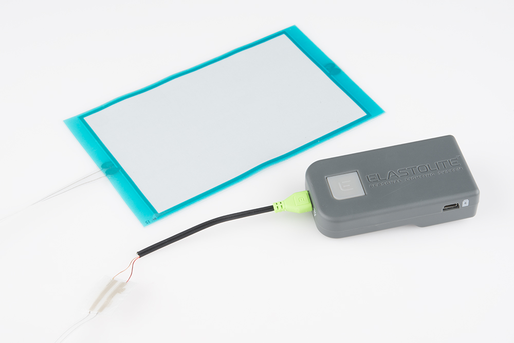
In this tutorial, we will be discussing ELastoLite EL Lamps from Oryon Technologies, and we will be showing you how to connect a single ELastoLite lamp to a single inverter. ELastoLite is desirable for use in E-textiles and wearable applications due to it’s waterproof outer covering and extreme flexibility. In addition, the circuitry is contained in an iron on casing that allows you to attach it to the inside of the garment or material eliminating free floating wires that can become disconnected easily or are just all around an inconvenience. It is imperative that you read this whole tutorial before attempting to add ELastolite to your garments as the process is not as straight forward as it seems, and there is lots of room for irreversible mistakes.
Now, you’re probably reading this tutorial because you’re confused about which parts you’ll need for your project. We didn’t put together a kit for ELastoLite because the parts needed will vary so much that a standard starter kit would benefit very few people. This tutorial aims to help you decide which parts you’ll need and how to connect them all.
NOTE: ELastoLite runs off of AC, similer to EL wire, and it can give you a slight shock if not handled properly. Please handle ELatsoLite panels, connectors, and inverters with care.
You Will Learn
Topics covered in this tutorial include:
- Plotting your design
- Choosing the correct parts
- Assembly techniques
- Proper care.
There will be a small amount of math, but I promise, we will make it as easy as possible. We understand not everyone likes math as much as us.
Suggested Reading
This tutorial builds on some previously discussed concepts. If you are unfamiliar with any of these, please check out the corresponding tutorial.
Required Materials
The very first thing you're going to want to do is gather all the materials you'll need. Here's our recommended list of tools and supplies to work with ELastoLite.
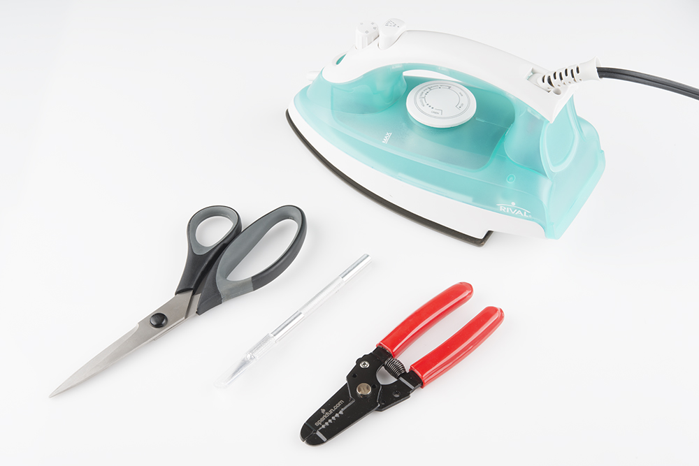
Iron
You’ll need an iron. Not a soldering iron, rather a fabric iron. The iron needs a cotton setting as that will be the optimum temperature to bond the connectors.
Hobby Knife
The circuitry will need to be stripped of it’s cover where the connections will be made. A hobby knife will make this easy.
Wax Paper
While some situations warrant the connector connection and ironing everything into the garment happening at once, others might go easier one at a time. Wax paper will help keep the iron on material sticking to your work surface. In addition, placing wax paper over top the circuitry when ironing it helps should you apply too much pressure or hold the iron on for too long.
Wire Strippers
There’s a small chance you may have to strip the inverter wires a little. So while not required, you might want to have a pair handy.
Patience
This can be a bit of a frustrating process. Keep your mind on the goal, and stay patient with yourself.
Choosing an Inverter
When choosing ELastoLite products, it's very important to take into account how much power your inverter can provide. Therefor, before you begin buying ELastoLite panels, you should look at the inverter options to make sure you have enough juice to power all the panel you want in your project.
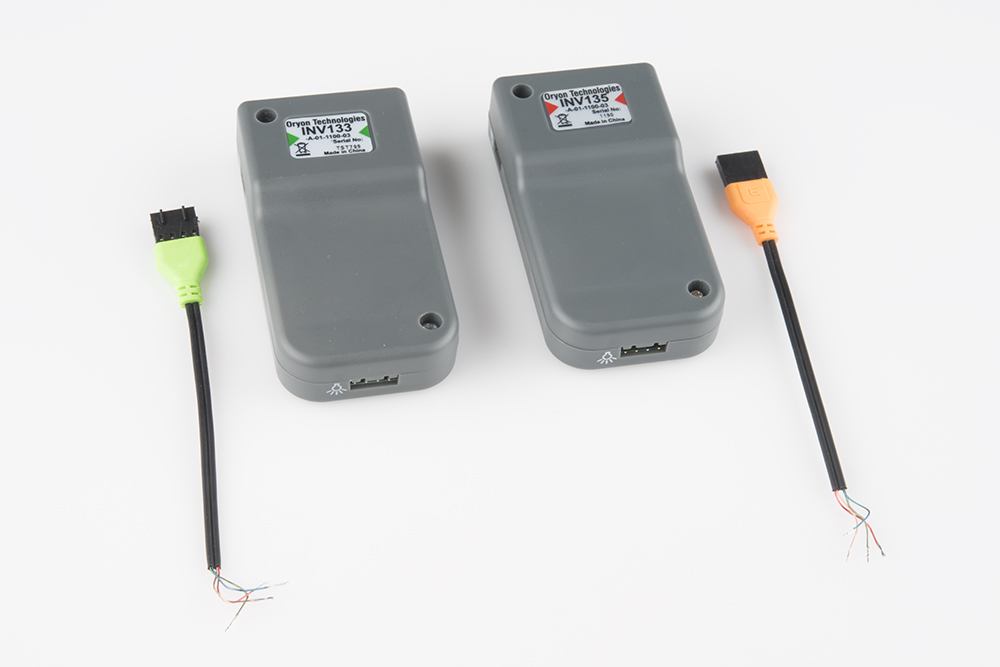
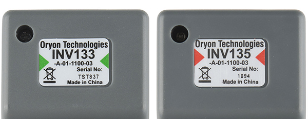
Oryon technologies have provided SparkFun with these great inverters designed specifically for ELastoLite. In addition to being rechargeable, the button is perfect for use in a garment. To cut down on the likelihood of false presses in a garment pocket, a prolonged press of the button is needed to change the flash rate or turn it on or off . There are two sizes of inverter, the INV133 and the INV135. Don’t let the numbers fool you, the INV133 is the more powerful of the two.
Which one you use will be dictated by how much lamp (panel space) you are using in your project. If the total area of the ELastoLite lamps you are using falls under 8 in2 then you want to use the INV135. It's important that you use this inverter for the smaller areas as the built in circuit protection of the inverter could trip should load not be large enough. If your total area falls between 8 in2 and 20 in2, then you want to use the INV133. Any area above that will be too much for a single inverter and will need a combination of two or more. Here’s a set of equations to use to calculate this:
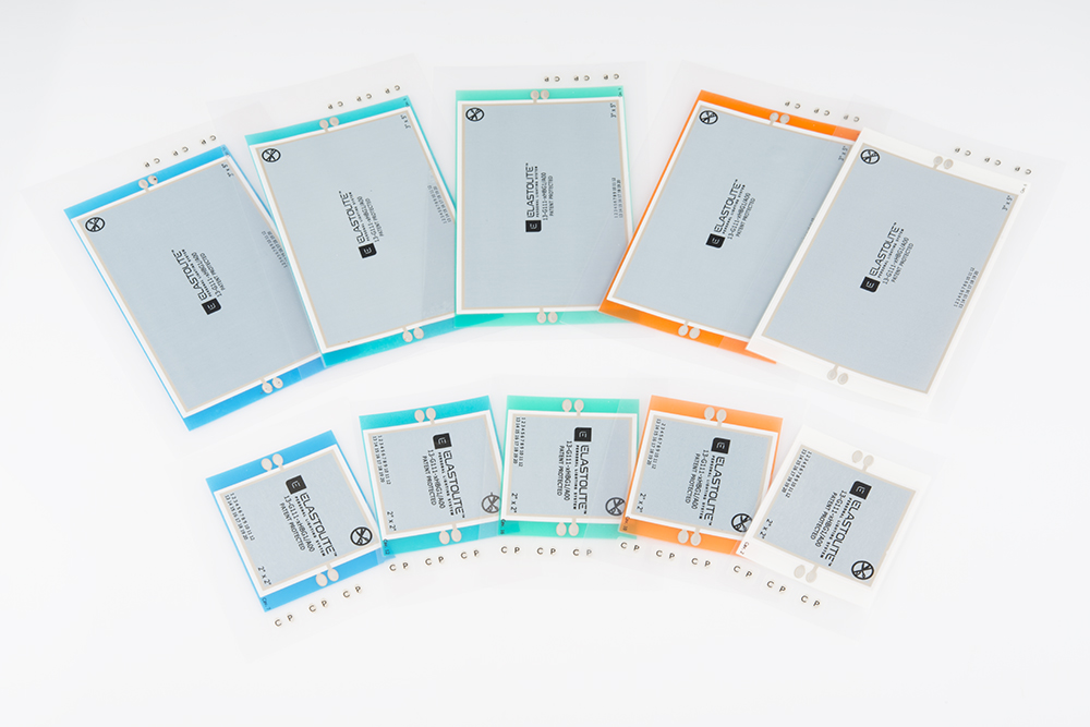
The dimensions on the product page for each panel should include the area of each lamp. If not, the numbers in the product title will suffice (example: 3x5 inch lamp has an area of 3*5 or 15 in²).
Once you have the correct inverter(s) selected, you need to choose Molex connectors to go with the inverters. If you haven’t started already, I recommend start writing down the bill of materials. There are two colors that are associated with the two inverters respectively. I highly recommend buying the correct color as this will serve as an excellent reference for which inverter your circuit needs to be properly powered. The inverters have fantastic safety features, so a smaller area of lamps might not draw enough current to turn off the safety feature of the INV133. Additionally, the INV135 won’t have enough power to power some of the larger lamp configurations. Buying the correct color Molex connector will save you a lot of frustration down the road.
The INV135 corresponds to the orange Molex connector and the INV133 corresponds to the green one. You can double check this by the colors denoted on the label on the inverters.
Charging the Inverter
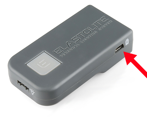
The inverters ship discharged, so you need to charge them before the first use. Simply plug the supplied USB Mini B cable to the Mini B USB connector on the inverter. This is the same method for re-charging when the inverter gets low on juice. Both the INV133 and the INV135 charge at 3.7V with a 1100mAh current. There is internal circuitry that regulates a 5V input down to the required 3.7V, so you can charge from a computer USB port or from a USB wall wart.
Choosing the Right Circuitry
You should now have lamps, an inverter, and a Molex Connector picked out. We now need to buy the circuitry and connectors to connect them all. Below is the exploded view of the connection to be made between the Molex connector and the iron on circuitry.
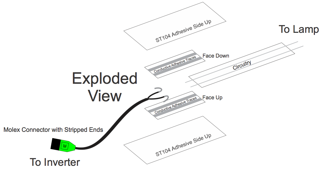
(Note: the top adhesive tape strip should be adhesive side down, not up as in the diagram above.)
To make this connection you will need two of the straight connectors. One goes on the top, the other on the bottom. Those will be encased in an outer layer of iron-on tape. You will only need 1 unit of that. We sell them in 2 inch lengths. When cut in half, it provides the proper amount needed for the top and bottom.
The next part needed is the circuit tape which will provide the connection between the Molex connector and the actual ELastoLite lamp. We sell these in 3 foot lengths. I don’t recommend making connections longer than that. However, if you wish to, repeat the straight connector connection outlined above in the exploded view. Rather than the Molex leads on the one end, use another length of the iron-on circuitry. The lengths will become fully enclosed, and the conductive thread in the circuitry will need to be exposed (which we will cover later).
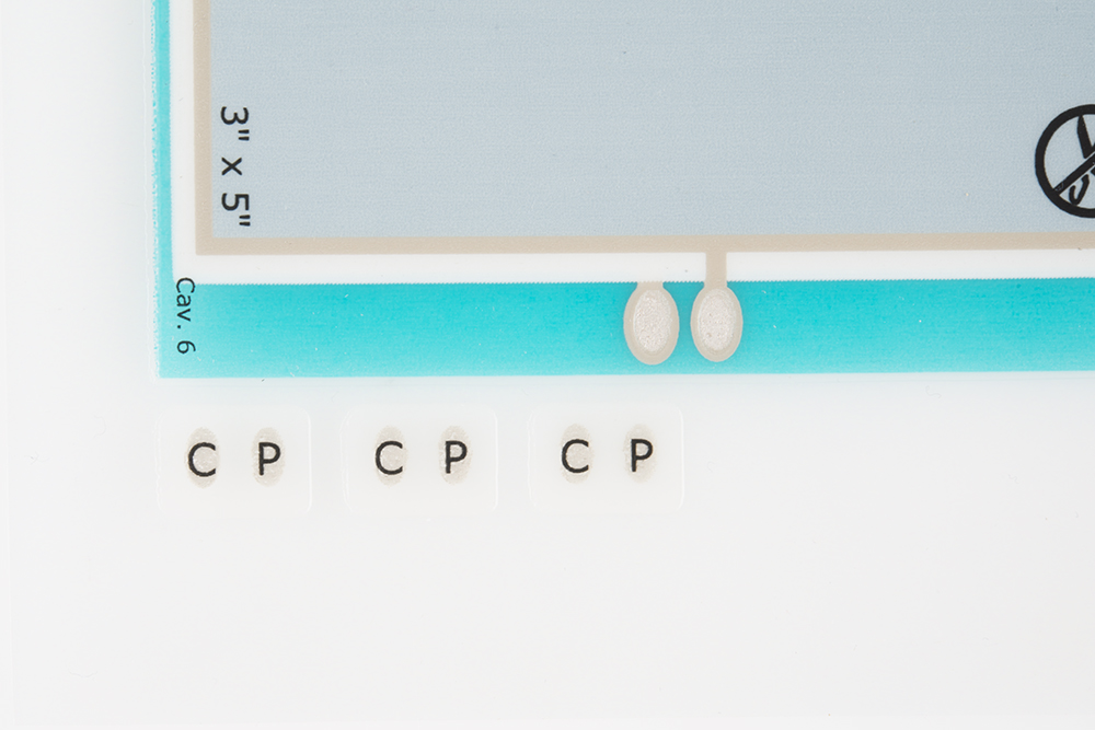
The contact patches that will help establish the connection between the iron on circuitry and the Lamp will be included with the Lamp (the little dots off to the side). Each Lamp comes with three patches. Two of the three will be used. The first will be used to establish the connection between the iron on circuitry and the lamp. The second one will do the same if there is a chain of more than one lamp. If not, the contact patch will be used to cover up the contact points on the Lamp which will be live when powered.
Buy ELastoLite Parts For Your Project
That’s an overview of the parts and their purpose. For this tutorial, I’m going to assemble a circuit of one 3x5 inch lamp and the INV133 inverter. Below is the wishlist for the parts that we're going to use in the next section. Feel free to add or subtract parts as you see fit.
Once you have figured out the parts you will need for this, place your order and get excited. There is an additional T-junction part that can be used, but we will not be covering this piece in the Assembly. If you wish to add a T-connector, instructions can be found in the Going Further section.
Assembly
ReplaceMeOpen
ReplaceMeClose
Now that you have all the parts and tools necessary, lets start assembling. First, plug the inverter into the USB cable and charge the inverter (you can use your computer port or a USB to wall socket power adapter). Lay out your fabric, and plot the path you’re going to want the circuitry to follow. Maintaining the shortest path possible is the main thing to conside. Also, do your best to route in a manner that keeps the connectors out of harms way such as areas where there with be lots movement, eg. shoulders, elbows, knees, etc. Another thing to consider is inverter placement. If it’s a garment, route it into a pocket. If not, make some form of support for it such as a pouch or straps. The circuitry will supply very little structural support for the heavy inverter, so you’re going to want to provide support to the inverter in another manner.
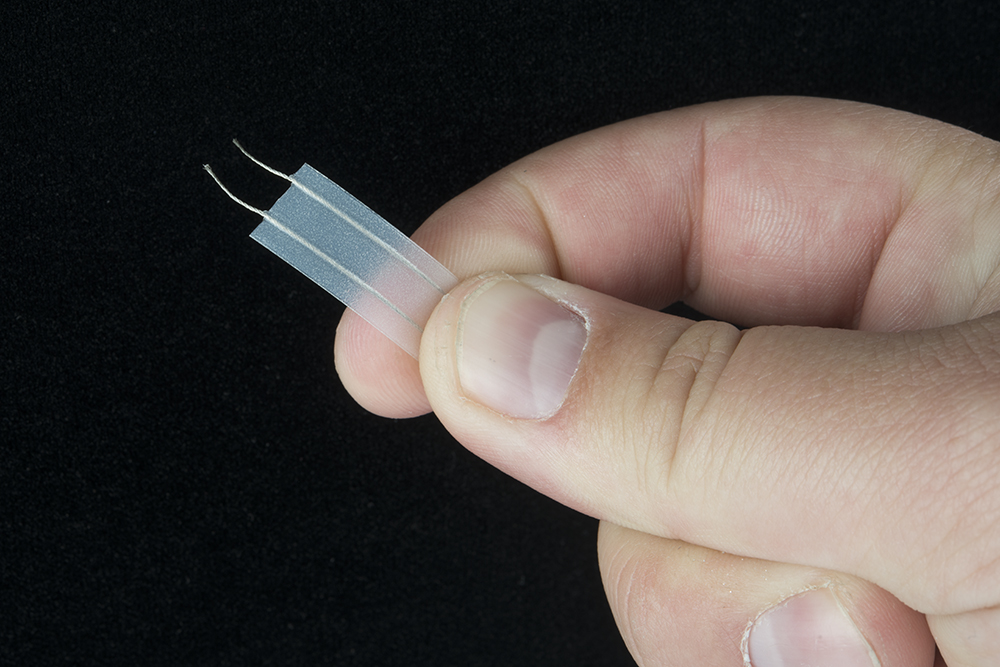
Once you have the circuitry cut to the length you need, you need to strip the ends. You’ll want about ⅕ of an inch on the end that will attach to the lamp and about ⅓ of inch on the end that will connect with the Molex connector. To strip the ends, simply take a hobby knife and make three incisions in the iron-on material perpendicular to the conductive thread. Be sure not to nick the thread as this could easily lead to a break in the thread after use. Once you have your three incisions, pull firmly yet lightly on the end of the iron-on sheath until it comes off, exposing the aforementioned lengths of thread.
Next, you need to decide whether you’re going to iron in the circuitry when making the connector or not. The process will be slightly easier if you do so now. If not, skip ahead to the part about making the inverter connection.
It’s time for some ironing. Go ahead and set the iron to the cotton setting. Once you have the circuitry path established, go ahead, and start ironing. Be sure to apply very little pressure as the weight of the iron will do most of the work, and keep everything as crease free as possible. Leave a couple of inches free at each end as it will be easier to work with when making the connections.

With the circuitry ironed in, we can start the molex connector assembly. Below is the exploded view of how it will go together. PLEASE READ THIS NEXT PART. The wire coming off molex connector is a bit deceiving. There are four wires, only two get used. The two wires we we'll be using are the red and tan wires. The other wires need to be clipped off. The remaining wires should be stripped. If not, gently strip ¼ of an inch of the wire with wire strippers. It doesn’t matter which wire goes on which side as we’re supplying AC power from the inverter to the lamp.
The straight connectors are going to be labeled with a “top” facing the direction that will go on the inside on the connection (the part you want touching the exposed wires). The iron-on tape that will form the outer layer of the connection needs to face a specific direction as well. You want the curve of the tape facing inward. If you can’t tell which side faces in, pinch it between your fingers and rub it back and forth. The side that sticks to your finger will face inward, and the side that faces out will slide across your finger. This is also the time to cut the tape in two equal pieces if you haven’t already.
If you’re not ironing this directly into the garment immediately, put some wax paper underneath before you bond the connector pieces. It’s imperative that the leads off the circuitry and the molex connector get sandwiched between the gray strips on each of the straight connectors. If they don’t sit in those strips, the connection won’t be made. Once you have everything in place like in the diagram above, place the iron over top for 10-15 seconds, then remove. Let it cool before handling it, the connection should be tightly secure. If you ironed the connection into the fabric when bonding it, make sure there’s no pockets of the circuitry that haven’t gotten ironed in (leave the lamp side loose still).
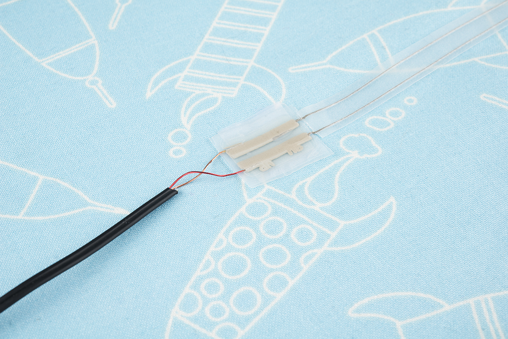
As I mentioned, the circuitry isn’t going to provide any support for the inverter, and you don’t want to risk the inverter pulling apart the bonded connection we just made between the circuitry and the molex connector. So, we’re going to sew in some support for the molex connector. I usually just sew an “X” over the outer insulation for the wire coming off the molex connector.
Now, we need to make the connection to the lamp. This connection is much more simple, thankfully. First, remove the lamp from the hard backing. If heat is applied too long, it could cause the lamp to bond to the backing. You’ll want the back (the side with the text on it) facing up, exposing the connection points (shown in the picture below).

Place the conductive thread over top the connection points then place the connection patch overtop with the letters “C P” facing up. Just like with the molex connection, sit the iron on top of the connection points for 10-15 seconds to make the bond. Let it cool, and insure the bond occurred and is stable. If not, there’s an extra connection patch that can be used to redo the bond.
Finally, if this is the last lamp in the daisy chain, you'll want use the third connection patch to close the exposed connection points as they will be live. Follow the steps previously outlined to make the connection to the conductive thread. Just omit the conductive thread from the process.
Fastening the ELastoLite Lamp to your garment requires a little bit of sewing. It is possible to purchase more of the conductive tape and iron it to the back of the lamp then iron that onto the garment (this is an approved method from Oryon Tech). However, you will still have the edges exposed. I personally recommend sewing a fabric frame around the lamp. This will also allow you to create a shape for the lamp as cutting it and retaining it’s waterproofing is not possible. If you want to create a shape where a lot of the lamp will be hidden, use a heavier fabric to prevent the lamp from shining through. Sewing in a frame will also allow for the potential to swap out lamps should something unfortunate happen to original.
Resources and Going Further
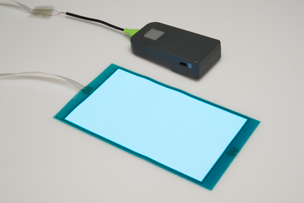
You should know have a blinky, glowy awesome ELastoLite panel. You should also have a good understanding of how to use the various ELastoLite parts to make your project come to life. Be sure to check out these other great resources:
- T Connector Process - This PDF will show you how to make a T junction for the ELastoLite panels, similar to the single connection junction we made in this tutorial.
- Inverter Instructions
For more e-textile awesomeness, you can check out these tutorials: