ProtoSnap LilyPad Development Simple Hookup Guide
 jimblom
Introduction
Interested in getting into LilyPad? Or maybe it's Arduino that tickles your fancy? Just want to add a little white-blinky-LED zest to your vest? All of the above? The ProtoSnap LilyPad Simple is a great tool to explore any of these subjects.
This tutorial is aimed at getting the reader familiar with a variety of topics including: LEDs, LilyPad, Arduino, buzzers, and just circuits in general. I'll cover the basics, like what's going on with all those copper traces all over the ProtoSnap, and what an LED does. We'll also discuss the steps required to load your first Arduino sketch onto the ProtoSnap.
Following that, we'll actually demo how you can make something with the ProtoSnap. We'll be breaking the pieces apart to build a high-tech fabric raygun!

Before we begin though, I'd just like to say one thing. You've probably seen this warning a few times, but just to reiterate:
Don't snap the ProtoSnap apart! Yet.
Continuing on then...
Before You Begin
This tutorial builds upon some concepts ranging from basic electronics to sewing. If you haven't already, it may help to review some of these tutorials:
- E-Textile Basics - Learn the basics of wearable electronics.
- Sewing with Conductive Thread - In the latter half of the tutorial, we'll be breaking apart the ProtoSnap and sewing it all back together. This tutorial explains the basics of working with conductive thread.
- Firefly Jar - This is one of the more basic e-textile circuits out there. You may want to try this one out before going all out with this example.
And there are a few general electronics concepts which might help to know a bit about:
- What is An Arduino? - The ProtoSnap LilyPad Development Simple board has an Arduino! Check out this tutorial if you're unfamiliar with what, exactly, this Arduino thing is.
- Voltage, Current, Resistance, and Ohm's Law - The fundamental rules governing all circuits, whether they're wearable or soldered.
- Series and Parallel Circuits - It helps to have a very basic understanding of series and parallel circuits
Hardware Explanation
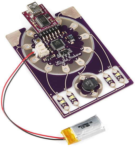
The ProtoSnap LilyPad Simple is a mish-mash of three unique LilyPad boards. Each of those boards are connected together, so you can explore, experiment, and test your Arduino programs without having to worry about wiring (or conductively sewing) any of the boards together.
LilyPad Arduino Simple Board
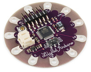
The LilyPad Arduino Simple is the brains of the ProtoSnap's operation. The heart of this board is that tiny black chip in the center – an ATmega328 microprocessor. A microprocessor is a tiny computer that can be programmed to interact with the LEDs, buzzers, and many other peripherals. The ATmega328 is one of our favorite microcontrollers - it's got a good set of inputs and outputs, lots of features, and it plays very nicely with the Arduino software.
The petals circling the LilyPad Arduino Simple board are the inputs and outputs of the microprocessor. The + and - petals are the power inputs to the chip, while the various A# and # labels are the outputs pins.
The other key components of this board are its two connectors. There's a beige, 2-pin JST connector, which mates with the included LiPo battery. The spiky, 6-pin connector facing the top of the board is the FTDI programming header. This connector interfaces with the included LilyPad FTDI Board, which we'll discuss a bit further below.
On top of that, there's a reset button, ON/OFF switch (which only works if the board is running off battery power), and two indicator LEDs (they're tiny, and hard to spot when the board is off).
LilyPad LED Boards
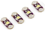
LEDs -- short for light-emitting diodes -- are the heart of every good, blinky electronics project. They're perfect for power indicators, debugging, or just adding a little zazz to your project.
LEDs have all sorts of light-related uses. You're no-doubt used to seeing them in light-emitting displays (clocks, traffic lights, signs, LCD backlights) or as energy-efficient light-sources (flashlights, architectural lighting), but they've also got less obvious light-related uses, like infrared remote controls, mouse-movement detectors, and they can even be hidden inside chips (optoisolators).
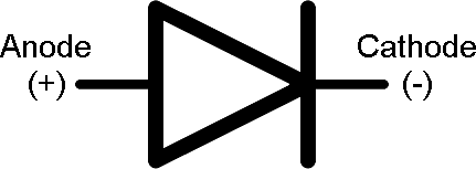
LEDs have two pins: an anode (+) and a cathode (-). When you apply the right amount of power to an LED, it will emit light.
The LilyPad LED boards have two petals labeled + and -. While the ProtoSnap remains unsnapped, the + pins each connect to a different pin on the LilyPad Arduino Simple board, while the - pins are all connected to ground.
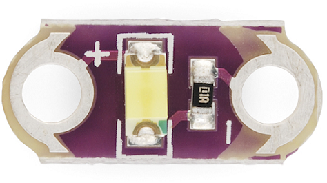
In addition to the LED, the LilyPad LED boards also include a current limiting resistor (those tiny, little, black rectangles). An essential part to any LED circuit, these resistors help make sure you don't burn up your LEDs.
LilyPad Buzzer Board
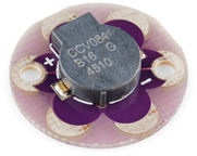
Finally we get to the buzzer. An essential piece to any project that intends to make some noise, even if that noise is the most annoying sound in the world (honestly, it's not gonna sound much better than that).
Buzzers like this can produce frequencies throughout most of our audible range. Feed it a series of tones and you can make musical melodies, special effect sounds, alarms, or whatever other sound-related application your project needs.
This buzzer board has two petals: a plus (+) and a minus (-). While living on the ProtoSnap, the - pin is tied to ground, and the + pin is tied to a pin on the LilyPad Arduino Simple. You'll be able to program the LilyPad Arduino Simple to toggle the + pin at different frequencies to create different tones.
LilyPad FTDI Basic Breakout
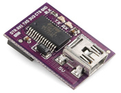
This board serves three separate purposes. First of all, it can power the LilyPad Arduino Simple. A power source for your project is one of the most important decisions you'll make. The FTDI Basic will source power from your computer's USB port, and relay it over to the LilyPad Arduino.
While powering the board is important, that's really what the battery is for. The FTDI Basic board's primary purpose is to help program your LilyPad Arduino Simple. The Arduino software interfaces with this board, which in turn interfaces with your LilyPad Simple board.
Finally, if a LiPo battery is connected to the LilyPad Arduino Simple board, power from the FTDI Basic will be used to charge that battery.
There are a couple LEDs on this board, labeled TX and RX, which will blink when data transfers from your computer to Arduino, or vice-versa. Look for them to blink like crazy when you upload code to the board.
Lithium Polymer (LiPo) Battery
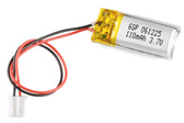
This little LiPo battery provides the power that is essential for most LilyPad projects. Instead of having to walk around with a USB cable coming out of your shorts, the battery gives you freedom to get your project running remotely.
We love LiPo batteries because they pack a lot of juice into a tiny package, they're generally easy to work with, and, best of all, they're rechargeable.
This single-cell LiPo will produce a voltage between about 3.6V and 4.2V, depending on its charge. The included battery has a rated capacity of 110mAh (that's miliamp-hours) which should be enough juice to power your project for at least three hours or so (assuming you're just blaring the LEDs and buzzer), probably much longer.
Eventually the LiPo battery will discharge to the point where it can't power the ProtoSnap. To charge the LiPo battery back up, you'll need to leave it connected to the LilyPad Arduino Simple board, while also plugging that board into an FTDI Basic Breakout (which should be connected to a USB cable...which should be connected to a computer's USB port. A lot of connecting). An orange charge LED indicator on the LilyPad Arduino Simple will turn on when the battery is charging, and will go off once the battery's full. It should take about an hour to charge the battery from dead to full.
LiPo batteries are wonderful, but they can prove dangerous if mishandled. Don't go stabbing it with an exacto knife, and only charge as detailed above.
The ProtoSnap Circuit
What's great about the ProtoSnap is all of the boards I mentioned above, sold separately, are mish-mashed and wired together. Before programming the Arduino board, it's important to know just how all of those boards are wired together.
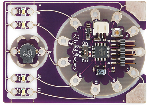
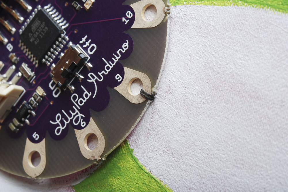
Each pin on the Arduino Simple Board is given a distinct number, which will be referenced in the Arduino code. Notice the white pin labels on the board - specifically those labeled 5, 6, 9, 10, 11, A2, A3, A4, and A5 - those are the pin numbers. They'll be used time and time again in your Arduino sketch.
On the ProtoSnap, these pins are wired up to LEDs or buzzers (or, in some cases nothing). If you want to control an LED, or activate the buzzer, it'll be important to know which pin they're connected to. There are a few ways to find this out: you can actually see and trace the wires -- the bronze-silver colored, squiggly lines running from one petal to the other -- or you can reference the pin number. Or, you can check back to this handy table:
| Arduino Pin Number | Component | Input or Output? |
| 5 | Left-most LED | OUTPUT |
| 6 | Middle-left LED | OUTPUT |
| 10 | Middle-right LED | OUTPUT |
| 11 | Right-most LED | OUTPUT |
| 9 | Buzzer | OUTPUT |
| A3 | Touch sensor | INPUT |
| 13 | On-board, green LED | OUTPUT |
To be clear, any of those pins could be configured as inputs or outputs. That input/output column is really only applicable when you're using this exact circuit.
The inputs with an "A" in their name are analog inputs. They're special. They can do everything a digital input can do, but they can also be used as an analog-to-digital converter. An ADC can read in a range of voltages, instead of just reading a high or a low. This makes them handy for sensing analog inputs (like the on-board touch sensor).
Powering It Up
Without further ado-do, let's plug the battery in and revel in blinky LEDs! Pick out the battery and the ProtoSnap board, and plug the battery's white connector into the LilyPad Simple's beige-ish connector. Make sure you match up the notch on the battery's connector, with the inverted notch on the board's connector. If it isn't already, switch the ON/OFF switch into the ON position.
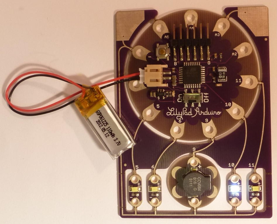
The ProtoSnap should run through its example sketch. The LEDs will light up in progression, the buzzer will buzz, and then nothing will happen. Seemingly nothing that is. Try touching both of those big, silvery, corner pads (labeled GND and A3) at the same time.
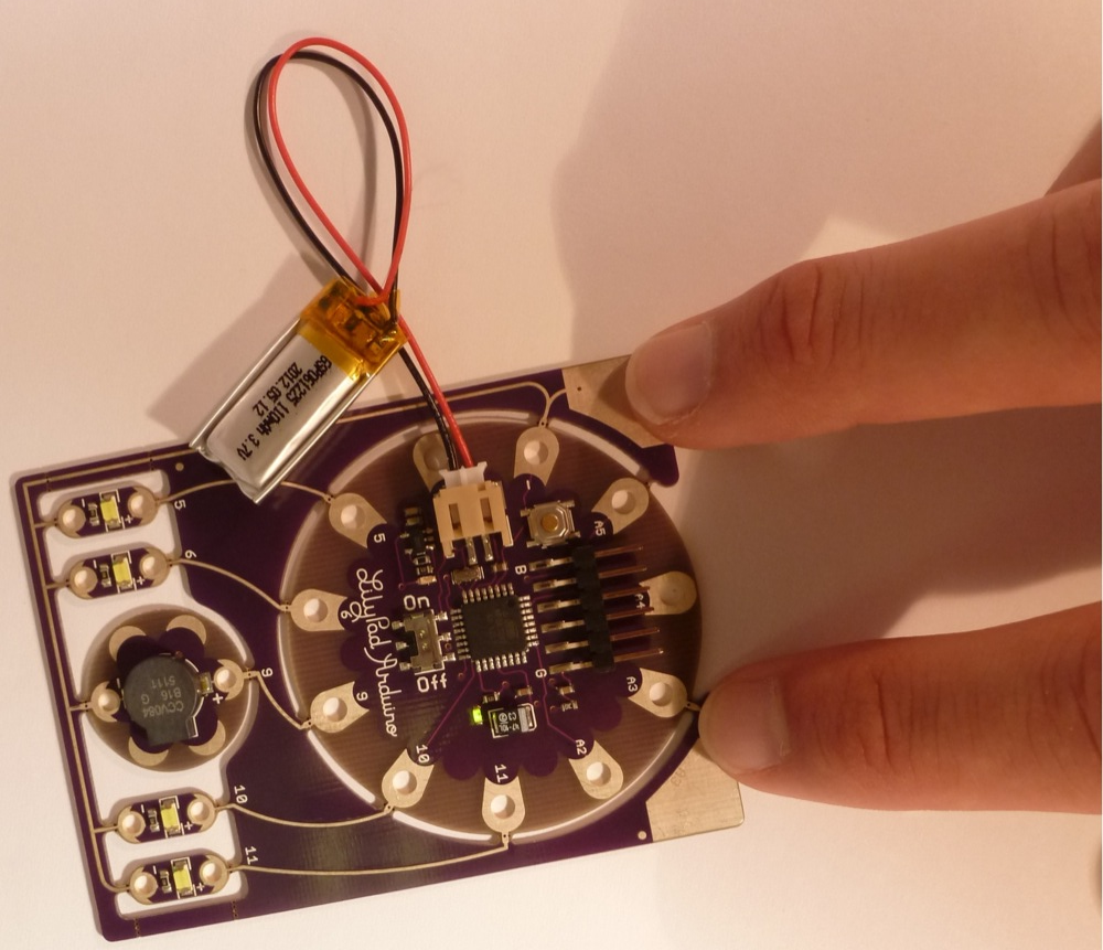
Turns out the example sketch has some really nifty code that can turn varying levels of touch-sensing into beautiful synth sounds.
If you want to relive the blinkiness, hit the reset button (it's a little gold circle surrounded by silver, up near the FTDI connector). Be gentle while hitting the reset button, and make sure you've got the ProtoSnap on a solid, level platform (speaking from experience, I just unsnapped my ProtoSnap's ground trace by hitting reset a little to hard).
Uploading an Arduino Sketch
Once you've gotten sick of the example sketch (as-if!), you'll no-doubt be itching to write and upload you're own piece of code. So, let's get right to it.
Install Arduino
You'll need to have Arduino installed from this point forward. You can grab the most recent version of the software from Arduino's downloads page. Check out our Arduino installation guide (Windows, Mac, or Linux) for help installing the IDE. When those tutorial speak of plugging in the Arduino to installing drivers, plug in the FTDI Basic board.
Savvy? Now, open up an Arduino window. You'll be greeted by something similar to this:
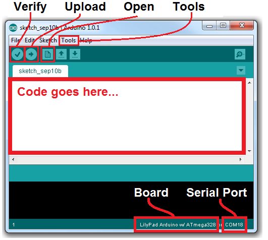
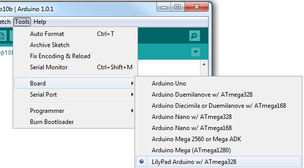
Before you can upload code, there are a few settings to make. Notice how in my picture above "Board" is correctly set as "LilyPad Arduino w/ ATmega328"? Yours is most likely not set that way. To change that, go to the Tools menu, navigate to the Boards dropdown, and select LilyPad Arduino w/ ATmega328. That tells the Arduino software what kind of board to compile code for.
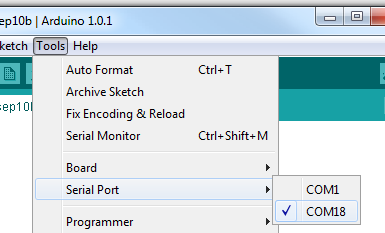
You'll also need to set the Serial Port, so Arduino knows that it's talking to your fancy new FTDI Basic board. Again go to Tools, and under Serial Port select your FTDI's port. On a Windows machine this is "COM#", on Mac your port will be "/dev/tty.usbserial###". Usually you should only have one choice available under this menu, pick that one. If you've got more than one (like me, I've got a COM1, which is my computer's ancient RS-232 port) a little trial-and-error won't hurt, or you can check for sure in the device manager.
Connect the FTDI Basic to LilyPad Arduino
Before you can upload the code, you'll need to connect the FTDI Basic to the LilyPad Arduino Simple board. There are "B" and "G" labels on the LilyPad Simple, which should line up with the "BLK" an "GRN" labels on the FTDI board. Line those up and slide the FTDI's female connector onto the mating pins.
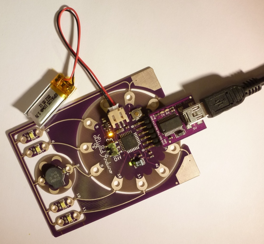
When you plug the FTDI board (assuming the battery is connected), you should see an orange LED light up, to indicate the battery is charging.
Upload Code
Sweet! Now the only missing ingredient is code. Which is quite the void, when it comes to programming recipes. Click here to download the Raygun example code we'll be using in the latter part of the tutorial (or you can copy/paste from below). Unzip that folder, and open "Raygun.ino" with Arduino.
language:c
/* RAYGUN!!! Example Code
   By: Nick Poole and Dia Campbell
       SparkFun Electronics
   Date: September 12, 2012
   License: This code is released into the open domain. Please
   use, re-use, and modify this code in any which way you
   require.

   This example code was written specifically for the ProtoSnap
   LilyPad Simple Development Board. After initializing the pins
   in setup(), this code jumps straight into making awesome,
   super-pleasant-sounding Raygun sounds. From time to time, the
   LEDs will sequentially light up (5->6->10->11).

   All sounds are labeled with an approximate onomatopoeia. You
   can move around the for() loops to make the Raygun that best
   suits you.
*/

const int buzzer = 9; //Buzzer pin
int freq; //frequency out (don't freak out)

void setup()
{
  // Set LED pins as OUTPUTs:
  pinMode(5, OUTPUT);
  pinMode(6, OUTPUT);
  pinMode(10, OUTPUT);
  pinMode(11, OUTPUT);

  // Set buzzer pin as OUTPUT:
  pinMode(buzzer, OUTPUT);
}

void loop()
{
  // BOOOOOOOOoooooooooo sound (descending) >>>>>>>>>>>>>>>>>>>>>
  // Goes from 1000 Hz to 340 Hz with 2ms delays in between
  for (int b=1000; b>340; b--)
  {
    tone(buzzer, b);
    delay(2);
  }
  // End of BOOOOOOOOoooooooooo <<<<<<<<<<<<<<<<<<<<<<<<<<<<<<<<<

  // Now call the ledZap() function. This is a function that we've
  // defined ourselves in the code below. Look under this loop to
  // see what the ledZap() function does.
  ledZap();

  // Turn the buzzer off, this must be called if the tone()
  // function was not given a duration (the 3rd paramater).
  noTone(buzzer);

  // DSIFGSIVOESRGJIOFDSJGFSD sound (white noise) >>>>>>>>>>>>>>>
  // This for loop plays 5000 random frequenices to create what
  // sounds like white noise.
  for(int i =0;i<5000;i++)
  {
    freq = random(240,1080);
    tone(buzzer, freq);
  }
  // End of DSIFGSIVOESRGJIOFDSJGFSD <<<<<<<<<<<<<<<<<<<<<<<<<<<<

  noTone(buzzer);  // Turn off the buzzer

  // WAWAWAWAWAWAWAWA sound (pacman waka) >>>>>>>>>>>>>>>>>>>>>>>
  // This set of for loops very quickly sweeps frequencies
  // down then up then down then up (10 iterations of down/up)
  for(int r=0;r<10;r++)
  {
    for(int c=1000;c>340;c--)
    {
      tone(buzzer, c);
    }
    for(int d=340;d<1000;d++)
    {
      tone(buzzer, d);
    }
  }
  // End of WAWAWAWAWAWAWAWA <<<<<<<<<<<<<<<<<<<<<<<<<<<<<<<<<<<<

  noTone(buzzer);

  ledZap();  // Zzzzzzzap

  // DSIFGSIVOESRGJIOFDSJGFSD sound (white noise) >>>>>>>>>>>>>>>
  // Same as the last DSIFGSIVOESRGJIOFDSJGFSD
  for(int i =0;i<5000;i++)
  {
    freq = random(240,1080);
    tone(buzzer, freq);
  }
  // End of DSIFGSIVOESRGJIOFDSJGFSD <<<<<<<<<<<<<<<<<<<<<<<<<<<<

  noTone(buzzer);

  // ooooOOOOBooooOOOOB sound (ascending) >>>>>>>>>>>>>>>>>>>>>>>
  // This set of for loops will twice sweep frequencies UP
  // from 340 Hz to 1000 Hz, with a small delay in between
  // each tone.
  for(int s=0;s<2;s++)
  {
    for(int g=340;g<1000;g++)
    {
      tone(buzzer,g);
      delay(2);
    }
  }
  // end of ooooOOOOBooooOOOOB <<<<<<<<<<<<<<<<<<<<<<<<<<<<<<<<<<

  noTone(buzzer);

  ledZap();  // Raygun be zapping


  // DSIFGSIVOESRGJIOFDSJGFSD sound (white noise) >>>>>>>>>>>>>>>
  // same white noise as usual.
  for(int i =0;i<5000;i++)
  {

    freq = random(240,1080);
    tone(buzzer, freq);
  }
  // End of DSIFGSIVOESRGJIOFDSJGFSD <<<<<<<<<<<<<<<<<<<<<<<<<<<<

  noTone(buzzer);

  // Now that we've reached the end of loop(), jump back up
  // to the top and do it all over again! Yay!
}

// the ledZap function quickly, and sequentially blinks
// each LED on and off. It'll blink pin 5, then 6, 10 and 11.
void ledZap()
{
  digitalWrite(5, HIGH);   // set the LED on
  delay(50);              // wait for 50ms
  digitalWrite(5, LOW);    // set the LED off
  delay(50);              // wait for 50ms

  digitalWrite(6, HIGH);   // set the LED on
  delay(50);              // wait for 50ms
  digitalWrite(6, LOW);    // set the LED off
  delay(50);              // wait for 50ms

  digitalWrite(10, HIGH);   // set the LED on
  delay(50);              // wait for 50ms
  digitalWrite(10, LOW);    // set the LED off
  delay(50);              // wait for 50ms

  digitalWrite(11, HIGH);   // set the LED on
  delay(50);              // wait for 50ms
  digitalWrite(11, LOW);    // set the LED off
  delay(50);              // wait for 50ms
}
Now, try Uploading that code, by clicking the right-pointing-arrow-icon button. Give Arduino few seconds to compile the code, and then a few more to upload. If all goes well, you should be greeted by something like this:
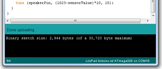
Yay! You uploaded some new code to the LilyPad Arduino Simple. As soon as the new code is uploaded, your Arduino Simple board should start running the Raygun code we'll use in the next part of the tutorial.
If you're having trouble with the upload, double check that the board and serial port are correctly set. Then, make sure the FTDI Basic board is properly plugged into the LilyPad Arduino Simple board ("B" goes to "BLK, and "G" goes to "GRN"). If you're still not having any luck, let us know in the comments below. You can also get in contact with our tech support team, who'd be happy to help.
This concludes part one of this tutorial. You've uploaded some code to the ProtoSnap (which should still be in one piece). In the remaining pages, we'll unsnap the Development Board, and break out the conductive thread to do some sewing!
Raygun Preparation
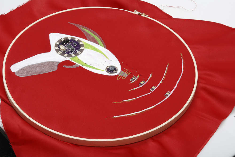
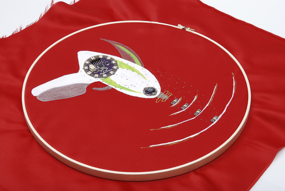
So, you've uploaded code, played around with it a little bit, and you've familiarized yourself with the components on the board. Now it's time to snap it apart and sew a circuit! If you want to use all of the components, you'll need something with a good use for lights and sound, so I'm just going to go ahead and say what we're all thinking- A RAYGUN!
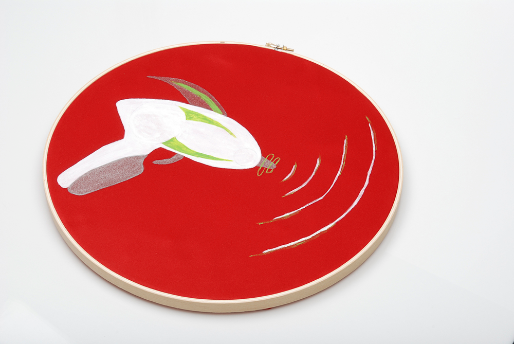
I started with a simple raygun painted onto a piece of fabric. There's really no end to the things you can sew this circuit onto. Feel free to run with your own ideas! I'm going to show you my circuit, but all I'm doing is laying out the components and sewing everything to the same pin it was already attached to on the board. You can absolutely make changes to this configuration, just make sure that if you change pins, your code gets changed to reflect that!
Required Materials
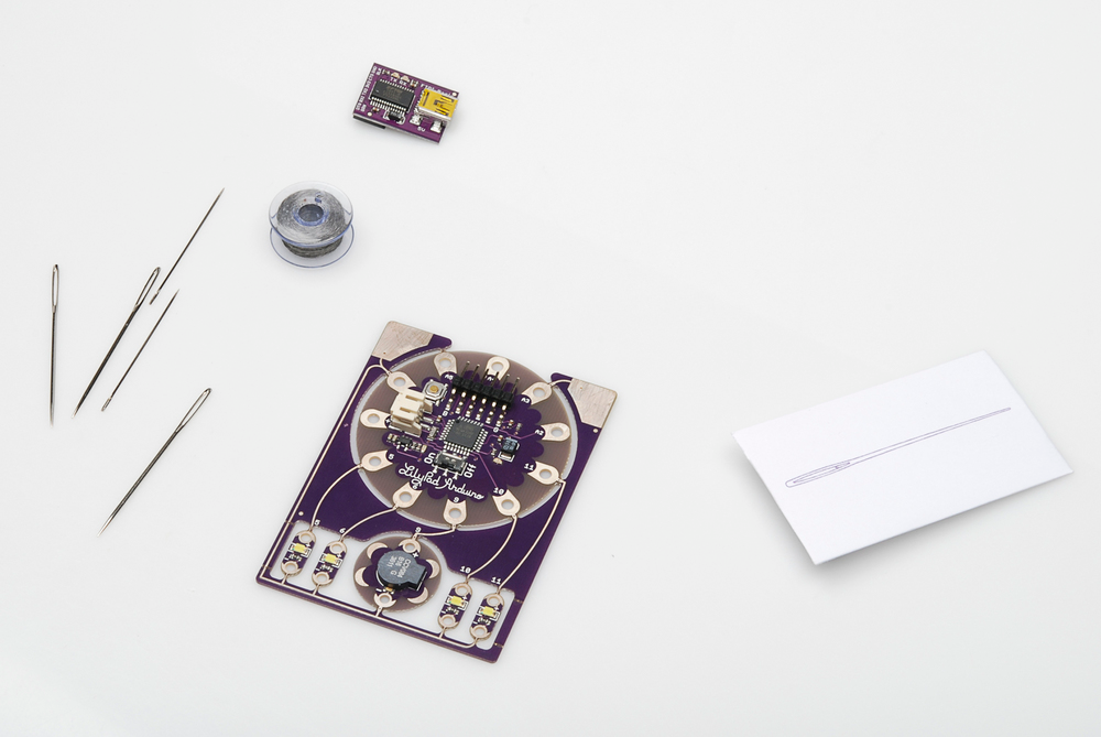
For this section of the tutorial, In addition to the things that came with your ProtoSnap, you're also going to need:
- Scissors
- Wire cutters
- Non-conductive thread
- Whatever you're sewing the circuit onto
Unsnapping and Tacking
I'm just going to go ahead and jump on in, since you guys warmed up on part 1! If you're here, you should have your code working adequately, so go ahead and snip the pieces of the ProtoSnap apart. I'll go ahead and take them all off at once. We'll get them all secured to the project quickly, so you shouldn't have to worry about losing parts. Use your wire cutters to snip the connections between the boards. Do this carefully -- you don't want to cut into or snap apart any of the hole you'll use for sewing later.
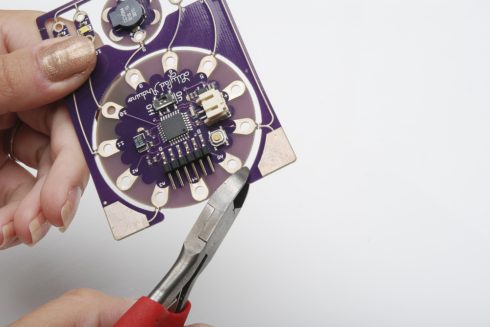
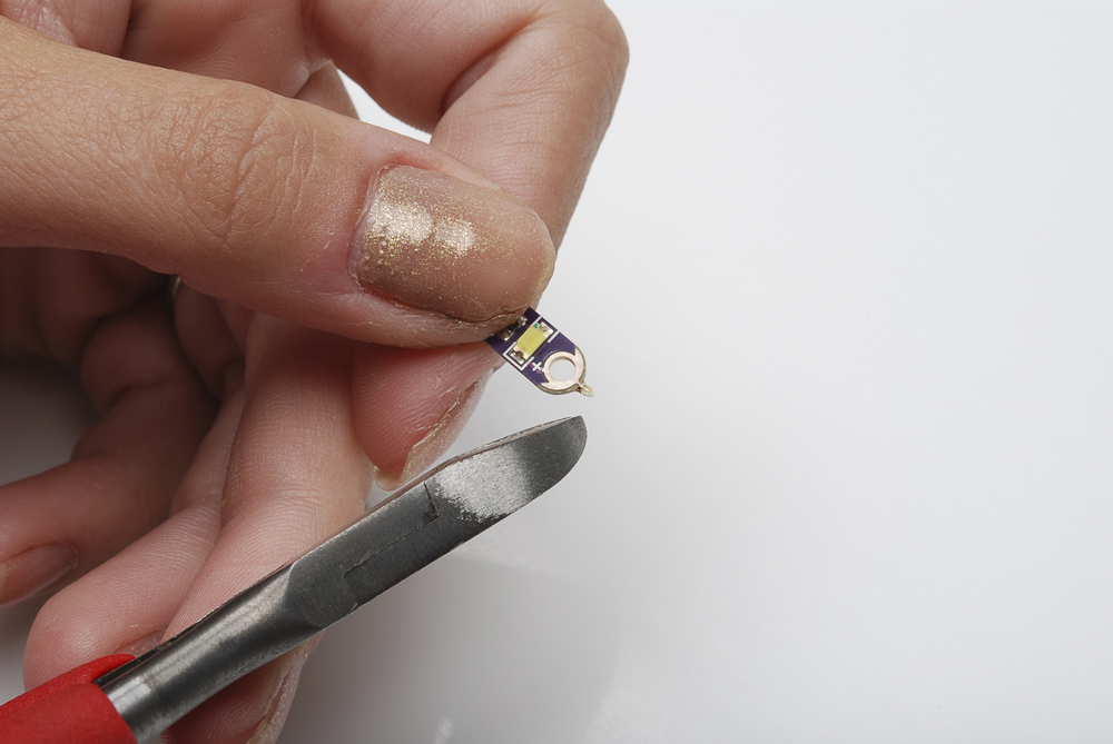
Make sure that you also snip off any extra sharp bits after you've taken these pieces apart
Once all of your parts are snipped apart and cleaned up nice and smooth, it's time to start sewing! Start with your non-conductive thread. We're going to go ahead and secure the parts to your project so that everything is already attached and oriented the way you need it to be. This will make it easier to connect things with your conductive traces, because it will be easy to see both the starting and ending point. Grab your Arduino simple board first. Turn it so that the "9" pin is facing where you want the buzzer to go. In my case, that's towards the tip of the ray gun. It won't take a lot of stitches- you certainly don't have to tack down every sewing hole on the board. I just chose two across from each other and sewed those down.
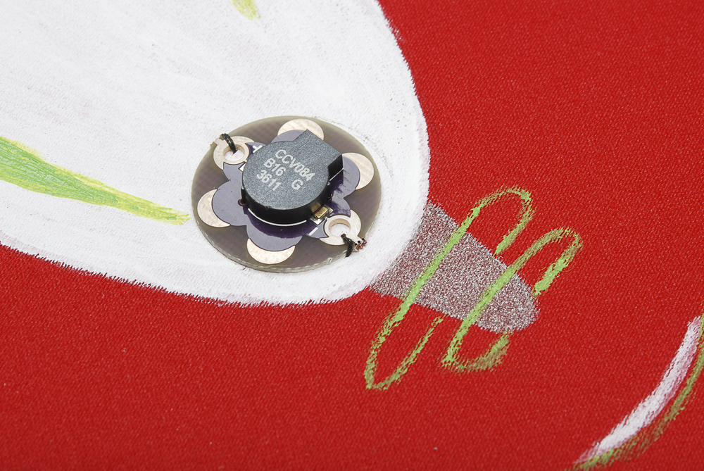
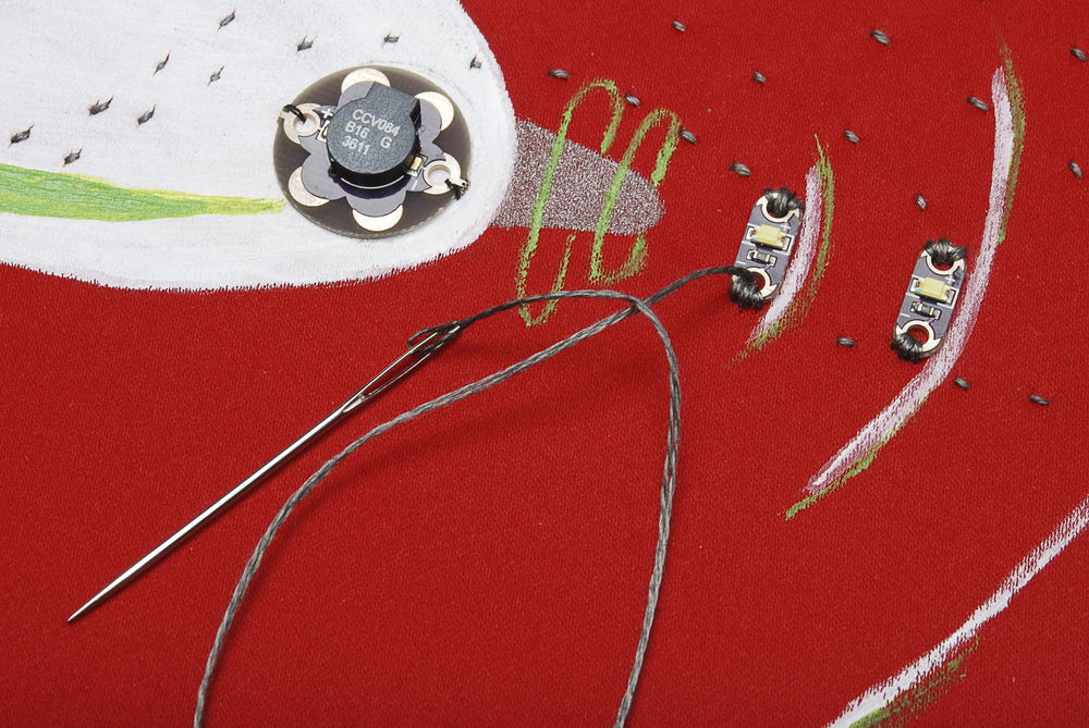
Next, let's tack down the buzzer. You'll want the positive pin pointed back towards pin 9 on the Arduino, and the negative pin pointed forwards, towards the tip of the gun.
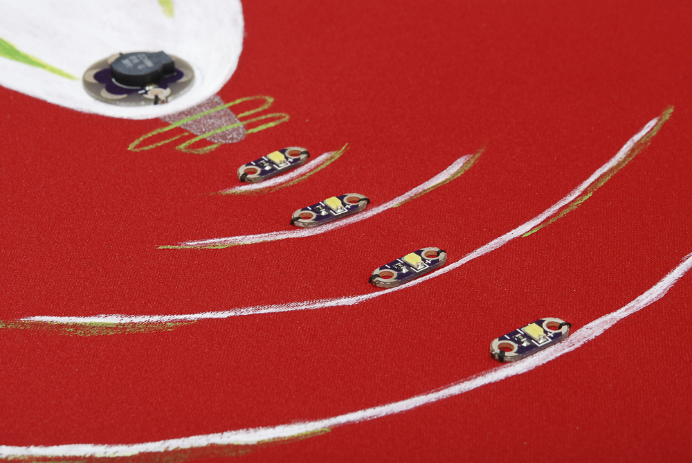
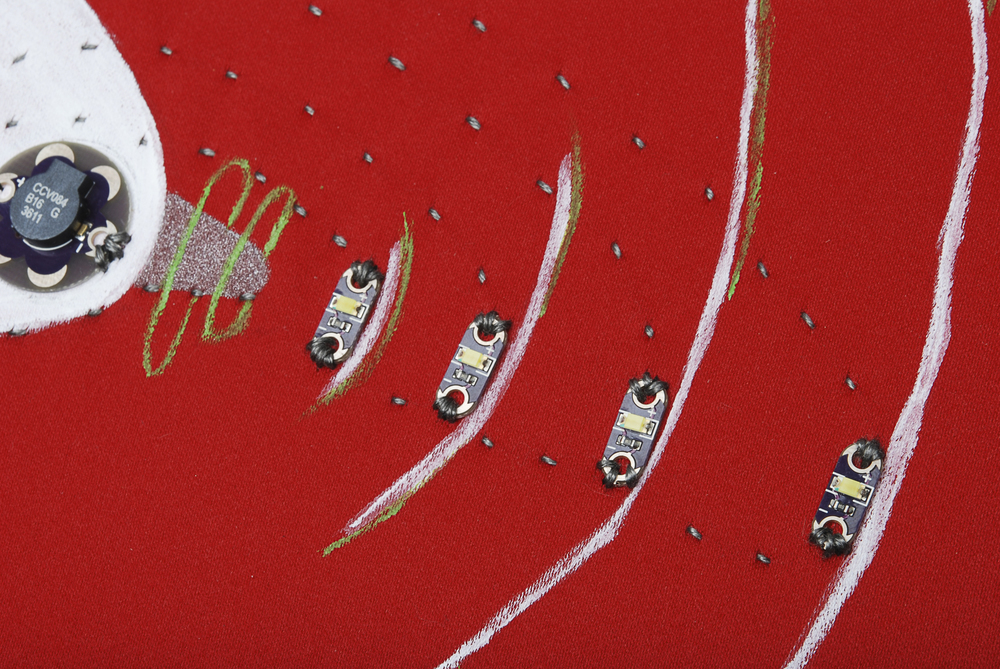
Finally, get the LEDs tacked down. You want them in a straight row, with the positive sides up and the negative sides down
Sewing the Positives
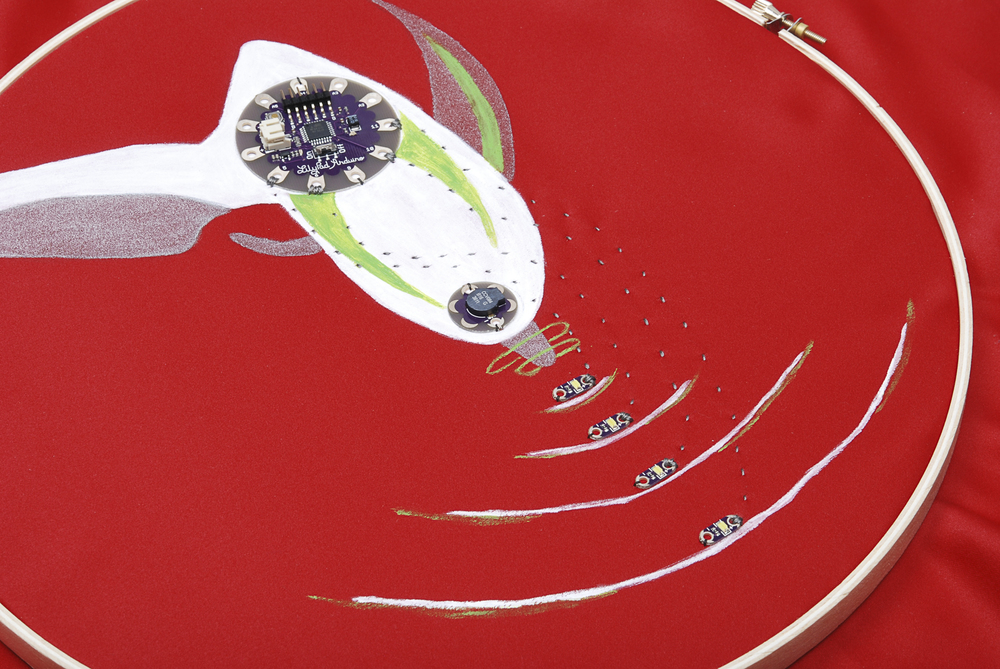
Now it's time to start sewing conductive traces! I know that the trace from the buzzer to pin 9 is a short, straight one, but we're going to skip that one for now. It has to cross a couple of the LED traces, so we'll do those first. Start with the LED closest to the buzzer, and stitch down the positive terminal with several stitches.
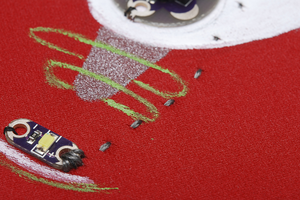
Sew from that positive hole to pin 5 of the Arduino board. You'll want to skirt around the buzzer a little ways, to leave room for the negative trace to leave the buzzer. When you get to pin 5, stitch it down several times before knotting and cutting your thread.

Sew down the positive side of the next LED, connecting it to pin 6.
Make sure you keep some distance between these traces -- you don't want them to touch.
Stitch down the positive side of the third LED and connect it to pin 10.

Stitch down the positive side of the last LED and connect it to pin 11.
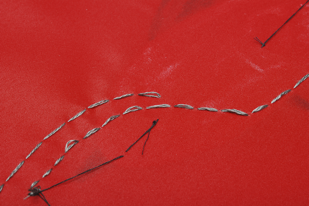
Take a second to double check that your traces aren't touching, both on the front and the back.

Sewing the Negatives
Let's get started on negative traces (or Ground)! Starting with the furthest LED out, stitch down the negative side, sew it to the next LED, and stitch that negative hole down. Continue down the line, sewing down each negative pad while connecting them all to each other.
Continue with this trace, sewing down the negative petal of the buzzer.
Continue this trace down and around to the negative pin of the Arduino. I neglected to get a picture of this connection, but just be careful not to touch the other traces and to pin it down well with several stitches. Next, cut and knot your thread, and get ready for the final trace! Sew down the positive pin on the buzzer.

Flip over the circuit to the back side. You can see the two traces between the LEDs and pins 5 and 6, which will need to be crossed. Cut a piece of felt or another thick fabric, or create an alternative bridge if you prefer- you just need something that will insulate between this trace and the previous ones.

It you are using felt, put a few stitches lightly through the top layer of fibers to the other side. Now you're safely past the previous stitches, and you can lift up the felt to confirm that the stitches in your felt haven't gone all the way through.
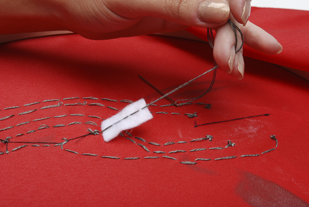
Now you can finish the trace, taking it to pin 9, and tacking it down. Tie off your thread and cut it.
And that's it! Those are all of your traces, so you should be able to plug your battery in, turn the switch to 'on', and check out your special effects! if your circuit doesn't work, there are a few things you can do. Use a multimeter to double check that all of your connections are firm, and that you don't have any shorts (places where traces touch that shouldn't.) If you haven't got a multimeter, check on these traces visually. If all of your traces are correct, try re-loading the code from part one of the quickstart guide. That should do it! Enjoy your new piece of raygun art!
Resources and Going Further
Did you build the Raygun? Or do you have a design of your own that you built? Awesome! If you're interested in learning more about e-textiles, check out some of these tutorials:
- LilyPad Design Kit Experiment 1: Lighting Up a Basic Circuit - The first experiment in the LilyPad Design Kit series. In this exercise, you will learn how a basic e-textiles circuit works, and light up a sewable LED using a coin cell battery holder and conductive thread.
- Soft Circuits: LED Feelings Pizza - Here we will learn how to say how you feel with pizza. Electric pizza.
- Getting Started with the LilyPad MP3 Player - The LilyPad MP3 Player is an amazing little board that contains almost everything you need to play audio files. You can use it to create all kinds of noisy projects, from MP3 hoodies to talking teddy bears. Your imagination is the only limit! This tutorial will help you get started.
- Mario the Magician's Magical Lapel Flower - A guest tutorial from the astonishingly talented Mario the Magician. A step-by-step tutorial to put together your own flower with an awesome video demonstration of its use!
Or, if you're feeling more inclined towards Arduino and other general electronics stuff, check out some of these tutorials:
- Pulse Width Modulation - PWM is the magic behind dimming and pulsing LEDs.
- Series and Parallel Circuits - After reading this tutorial, can you tell which type of circuit we used in the Raygun example of this tutorial?
- How to Read a Schematic - Learn how to decipher schematics, even that of the ProtoSnap LilyPad Development Simple board.