EL Sequencer/Escudo Dos Hookup Guide
 Toni_K
Introduction
The SparkFun EL Sequencer is an Arduino-comptabile microcontroller, with circuitry for controlling up to eight strands of electroluminescent (EL) wire. The Arduino shield version of the Sequencer is the SparkFun EL Escudo Dos, and it can be used with any Arduino Uno footprint-compatible microcontroller.
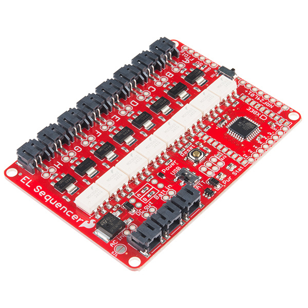
SparkFun EL Sequencer
COM-12781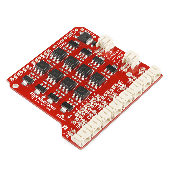
SparkFun EL Escudo Dos
COM-10878Materials Required
To follow along with this tutorial, we recommend you have access to the following materials in addition to your Sequencer or Escudo Dos.
Suggested Reading
If you aren't familiar with the following concepts, we recommend reviewing them before beginning to work with the EL Sequencer or Escudo Dos.
How to Solder: Through-Hole Soldering
Battery Technologies
How to Power a Project
Installing Arduino IDE
Alternating Current (AC) vs. Direct Current (DC)
Getting Started with Electroluminescent (EL) Wire
Arduino Shields v2
Hardware Overview - Comparison
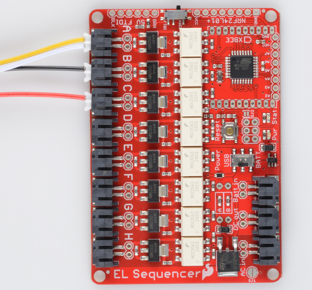
This section will cover the features that are shared between both the EL Sequencer and the EL Escudo Dos.
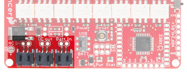
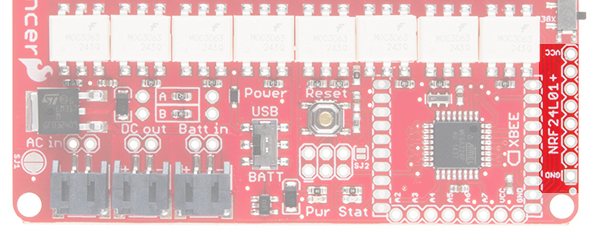
External Power Headers
The EL Sequencer and Escudo Dos have ports for power.
 |
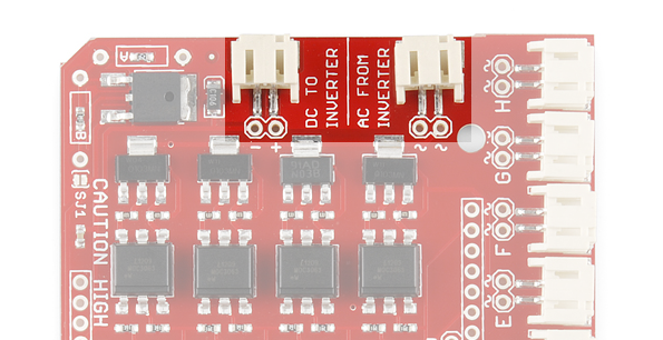 |
| External Power Headers on the EL Sequencer | External Power Headers on the EL Escudo Dos |
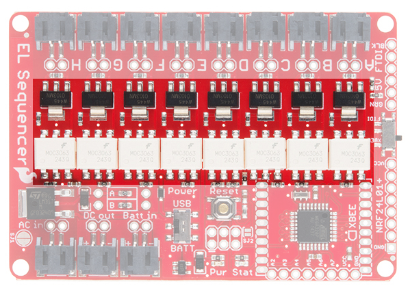
There are three power connection points on the Sequencer. The first is the AC In connection, which is the default connection point for any external inverter. The second connection is the DC Out line, which will connect to any inverter that does not have an external power supply. This provides a DC power supply to the inverter from the EL Sequencer itself. The final power connection is the Batt In connection. This allows the user to provide a power supply from a 3.7V lipo battery, or other power supply of 3.5V-16V.
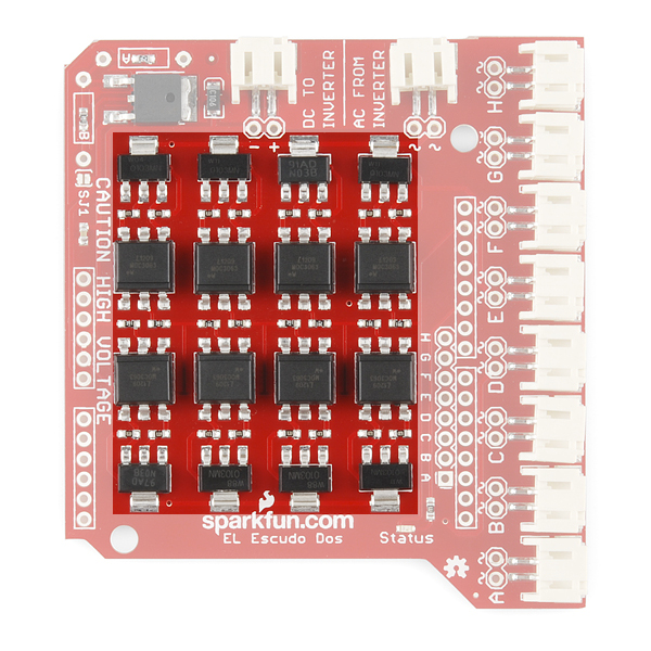
These can be connected via a standard 0.1" 2-pin header, or via the JST connector available on each line. If you ever forget the purpose of these connections, they are clearly labeled on the bottom of the board. The power headers on the EL Escudo Dos have the same functionality as the EL Sequencer. However, there is no Batt In header. This is because the power for the Escudo comes from the VRAW line on the connected Arduino or RedBoard.
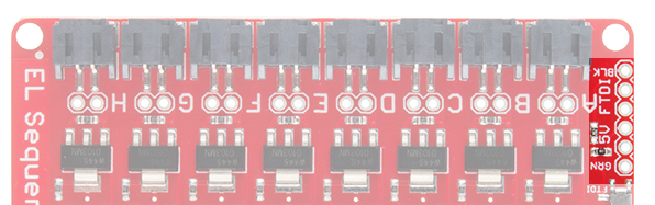
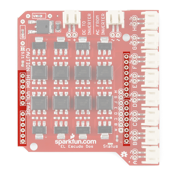
Channel Headers (HIGH VOLTAGE)
 |
 |
| EL Sequencer Channel Headers | EL Escudo Dos Channel Headers |
As the silk on the bottom side of the board states, there is high voltage in this area of the board. Care must be given when handling the board in a powered state, to prevent a shock to the user. These channels output the AC current needed to drive the EL wire. This is output at 100+V AC, 4000Hz (dependent on the inverter used). Each channel (A-H) is attached to one digital pin on the ATMega328 (pins 2-9, respectively). Driving the digital pins HIGH triggers the EL wire to turn on.
These can be connected to EL devices (wire, panels, etc.) via a standard 0.1" 2-pin header, or via the JST connector available on each line.
Solder Jumpers
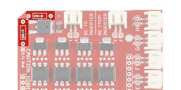
- SJ1 - This jumper allows the user to bypass the LM317 regulator when it's shorted. This regulator is used for external inverters. If left open, the regulator output voltage can be modified by user-supplied resistors on RA and RB pads. More on that below.
 |
 |
| Solder Jumper 1 on the Sequencer. | Solder Jumper 1 on the Escudo. |
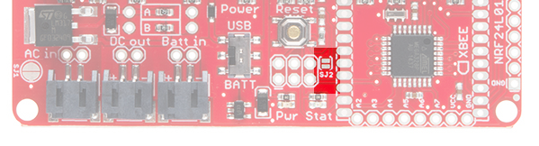
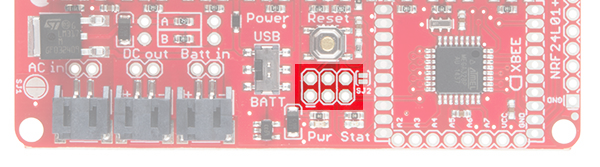
- SJ2 - This jumper is included as an option for wirelessly uploading of code to the Sequencer via XBee. This feature is experimental, and no guarantees are given for this feature's functionality.
TRIACs and Optoisolators
The main functionality of the Sequencer/Escudo comes from the TRIACs (Triode for Alternating Current) on-board. The MO3063S TRIAC Optocoupler takes the logic output from the associated ATMega328 digital pin which triggers the Z0103MN TRIAC to open the flow of the AC current from the inverter through the gate to drive the EL channel. This keeps the AC side of the circuit optically isolated from the DC portion of the circuit.
 |
 |
| EL Sequencer TRIACs and Optoisolators | EL Escudo Dos TRIACs and Optoisolators |
Adjustable Voltage Regulator
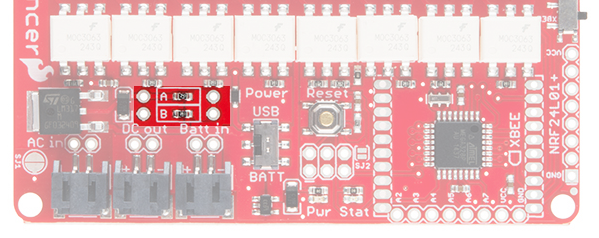
The LM317 voltage regulator on this board is adjustable based on the resistor values applied to it. By default, this board comes shipped with a 390Ω resistor on R1 and a 240Ω on R2. However, footprints for thru-hole resistors (A and B) have been added for the user to adjust the voltage out to their project needs. You'll need to remove the SMD resistors first. Then add thru-hole resistors of your choice. See the LM317 Datasheet for more information on which resistor values correspond to which voltage output.
 |
 |
| Resistors A and B on the EL Sequencer | Resistors A and B on the EL Escudo Dos |
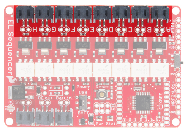
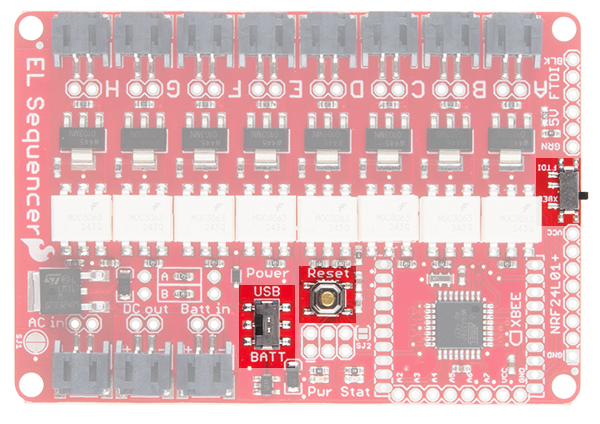
Hardware Overview - EL Sequencer
This section will cover the unique features of the EL Sequencer.
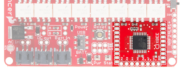
NRF24L01+ Header
This header is designed to interface with an NRF24L01+ module breakout. This provides a 2.4GHz signal to the EL Sequencer, which provides remote control options for the Sequencer at up to a 100m range.
FTDI Header
This is a 5V FTDI header, which is given to provide simple access for reprogramming the ATMega328 via serial connections. This can also be used to have the EL wire triggered via serial data in to the system.
XBee Header
This connection is provided to give users the option of wirelessly connecting the EL Sequencer via XBee. This can be used for mesh networking of several different Sequencers together (this is great for group costume projects), or remote control of the Sequencer.
ICSP Header
This 6-pin header is provided to allow the user to reprogram the ATMega328 on board via an external programmer. This also allows you to reprogram the EL Sequencer without the requirement of the Optiboot loader from the Arduino IDE.
Analog Input Header
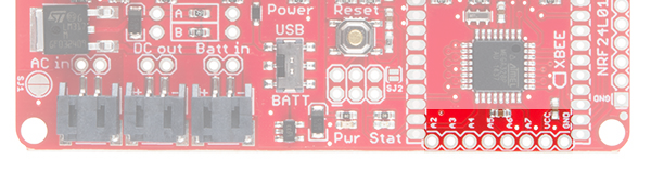
The additional analog pins on the ATMega328 are broken out to a standard 0.1" header on the EL Sequencer. This also gives the user the capability to trigger the EL wires from analog inputs (such as a photocell, temperature sensor, or a line sensor ).
Pins A6 and A7 are analog input only. Pins A0-A5 can be used as an analog input or as a digital I/O.
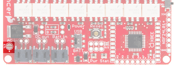
Switches and Reset Button
XBee to FTDI (far right, center) - This switch changes the RX line from being supplied via the FTDI header or the XBee. If attempting to program the Sequencer via FTDI, this switch must be set to the FTDI side.
USB/BATT (bottom, center) - This switch changes the power source for the ATMega328. The USB setting allows the ATMega328 to be powered via the FTDI connection, while the BATT setting allows the Arduino part to be powered off of a lipo battery instead.
Reset Button - Resets the Arduino sketch running on the ATMega328. It pulls the RESET line low, allowing the system to reset.
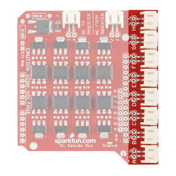
Hardware Overview - EL Escudo Dos
This section will cover the unique features of the EL Escudo Dos Arduino Shield.
Shield Headers
These headers allow the shield to be connected to any Arduino Uno/Uno R3 compatible board. We will be using the SparkFun RedBoard for this example.
Channel Headers
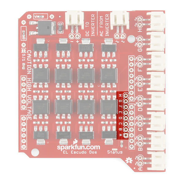
The EL Escudo also provides a row of 0.1" spaced headers to allow the user to read the signals from the microcontroller to the EL wires. This is beneficial for debugging.
Hardware Hookup
To get started using the EL Sequencer or EL Escudo Dos, there are a few basic steps that must be completed.
Solder Headers
EL Sequencer
At an absolute bare minimum, you must solder 6 pins on the FTDI header. For simplicity's sake, we recommend using male headers (either straight or right angle as these are compatible by default with the FTDI breakout). This will enable you to program the EL Sequencer via an FTDI breakout board.
If you plan on using an XBee unit with your Sequencer, you will also want to solder XBee Sockets to the board. If you plan on using any additional connectors on the board, you will also want to solder those headers on now. Keep in mind you may also want to trim off any excess header on the bottom of the board if you intend to use this in a wearable application.
EL Escudo Dos
Thanks to the simplified design, you only need to solder Arduino shield headers onto the Escudo. If you want to use any additional components in your project (such as wireless modules or external sensors), you will want to use stackable headers.
Connect the EL Wire
You have 8 channels available on the Sequencer to which you can plug in EL wire, chasing EL wire, or EL panels.
Please check out this tutorial on working with EL Wire specifically, and the current requirements for different types of materials.
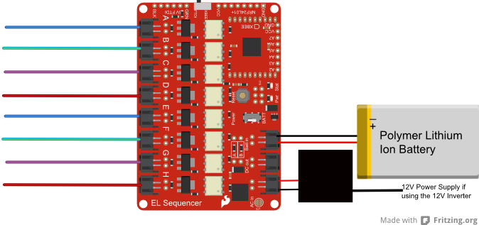
Connect the Inverter
Once you have hooked all of your EL wires up, the next step is to hook up the inverter.
3V Inverter - If you are using the 3V inverter, you will need to hook up both wire pairs from the inverter to the Sequencer. The black/black wire pair will plug into the
AC InJST connector, while the red/black wire pair plugs into theDC OutJST connector.12V Inverter - While using the 12V inverter, there is only one wire pair that will plug into the Sequencer. The red/black wire pair will plug into the
AC InJST connector. You will need a separate power supply to run this inverter (such as the 12VDC 600mA Wall Adapter).
Connect the Power Supply
EL Sequencer
If you are using a battery for the power supply, you can connect this to the Batt In JST header without altering the board. Using an external power supply with the 3V inverter will require closing SJ1. You will need to connect that supply to the PTH headers labeled Batt In. Make sure the power supply falls in the range of 3.5V-16V for an external power supply.
EL Escudo Dos
The power supply for the EL Escudo Dos actually comes from the Arduino. We recommend using a 12V wall adapter for powering the Arduino.
Alternatively, if you would like to go wireless, you could use a male barrel jack adapter along with a 12V battery. Typically, however, the EL Sequencer will be a better option for you for wireless applications.
Final Circuit
Once everything is hooked up, your circuit should look something like the following:
Arduino Example Code
Note: This example assumes you are using the latest version of the Arduino IDE on your desktop. If this is your first time using Arduino, please review our tutorial on installing the Arduino IDE. If you are unsure about installing the FTDI drivers, please check out our tutorial on How to Install FTDI Drivers.
Once you have all of your hardware hooked up properly, it's time to program your Sequencer to run the EL Wire display as you want. You can download the most up-to-date code from the EL Sequencer GitHub repository. Or you can download the Arduino code in order to follow along with the example. We will be working with the "SparkFun_EL_Example.ino" example.
Board Selection
**If using the EL Sequencer: **
Plug in your FTDI board to the computer via USB, and insert the FTDI onto the EL Sequencer. Make sure you match up the BLK to BLK and GRN to GRN labels.
When uploading your code, please be sure to select the following settings in the IDE:
- Board: LilyPad Arduino
- Processor: ATMega328
- COM port: Whichever port the FTDI Basic appears on for your operating system.
**If using the EL Escudo Dos + RedBoard: **
Plug in the RedBoard to the computer via USB. Select the following settings in the IDE:
- Board: Arduino Uno
- COM port: Whichever port the FTDI Basic appears on for your operating system.
Demo Example Code
This basic demo will cycle through each channel on the Sequencer, one by one, repeating until the system is either reprogrammed or turned off.
In the first section, we must define each pin that we will be using on the ATMega328.
language:c
/*******************Setup Loop***************************/
void setup() {
  // The EL channels are on pins 2 through 9 on the ATMega328
  // Initialize the pins as outputs
  pinMode(2, OUTPUT);  // channel A
  pinMode(3, OUTPUT);  // channel B
  pinMode(4, OUTPUT);  // channel C
  pinMode(5, OUTPUT);  // channel D
  pinMode(6, OUTPUT);  // channel E
  pinMode(7, OUTPUT);  // channel F
  pinMode(8, OUTPUT);  // channel G
  pinMode(9, OUTPUT);  // channel H

//Uncomment the following line if using this on the EL Escudo Dos.
// Pin 10 is a status LED on the EL Escudo.
//  pinMode(10, OUTPUT);

//Pin 13 is the status LED on both the EL Sequencer and Arduino for use with the EL Escudo Dos.
   pinMode(13, OUTPUT);
}
Each pin is declared as an output, which will allow us to drive the channel HIGH or LOW. We will cycle through each channel, turning them on individually, waiting 1/10 second, turning off, and moving to the next channel.
language:c
/*******************Main Loop***************************/
void loop()
{
  int x,status;

  //Step through all eight EL channels (pins 2 through 9)
  for (x=2; x<=9; x++)
  {
    digitalWrite(x, HIGH);   // turn the EL channel on
    delay(100);              // wait for 1/10 second
    digitalWrite(x, LOW);    // turn the EL channel off

//digitalWrite(10, status);   //Uncomment this line if using the EL Escudo Dos
digitalWrite(13, status);   // blink status LEDs
    status = !status;
  }
}
Each time a channel is cycled through, the status LEDs on the board will blink.
Once the code is uploaded, you should see each strand of EL wire light up one by one. If you aren't seeing that, verify that you have the correct power settings on the USB/Batt switch, and that the inverter is connected properly, switched on (if using the 12V inverter), and that the power supply to the board is properly charged and/or connected.
Going Wireless
If you would like to add wireless capabilities to your project, there's just a few more steps to get up and running.
**Insert a radio unit: ** You can either use a paired XBee unit or an NRF24L01+ module. You will need to make sure headers are soldered on for either device. If you need additional information on adding an XBee module, please check out our tutorial here. On the EL Sequencer, you will also need to flip the XBee to FTDI switch to XBee to ensure XBee communication is working properly.
Update the Code
If using a Series 1 XBee:
Upload the 'SparkFun_XBee_EL_Sequencer.ino' sketch to your board. In the first section, the status LED is declared as an output, and the Serial connection is opened at 9600bps.
language:c
//Declare character 'val'
char val;

/*******************Setup Loop***************************/
void setup(){
  Serial.begin(9600); //Begin Serial communication for debugging
  pinMode(13, OUTPUT); //Set pin mode as output for status LED
  val = 'A';// button pressed, therefore sending  letter A

  Serial.println("EL Sequencer's XBee is Ready to Receive Characters");
  digitalWrite(13,LOW); //set Status LED off
  delay(1000); //Wait 1 second
}
The main loop of the code simply waits for the XBee unit to receive the character 'A' from a remote XBee unit. If the character is received, the status LED is turned on, and a message is output to the serial terminal.
language:c
/*******************Main Loop***************************/
void loop(){

  //Check if XBee is receiving data from other XBee
  if(Serial.available()){
    val = Serial.read();

    //Check to see if character sent is letter A
    if(val == 'A'){
        digitalWrite(13,HIGH); //turn ON Status LED
        delay(50);
      Serial.println("Character Received");
    }

    else{
      digitalWrite(13,LOW); //turn OFF Status LED
    }
  }
}
If using an NRF24L01+:
You will need to use the RF24 library with the nRF24L01+ boards. We have a tutorial with more information regarding installing this library here.
We recommend using the RF24/examples/Usage/led_remote.ino example sketch. This is already configured to be compatible with the EL Sequencer with 6 channels of EL wire attached and will trigger each channel based on buttons hit on the remote unit.
The EL Sequencer will trigger the channels on and off based on the LED role in the code.
language:c
      //
      // LED role.  Receive the state of all buttons, and reflect that in the LEDs
      //

      if ( role == role_led )
      {
        // if there is data ready
        if ( radio.available() )
        {
          // Dump the payloads until we've gotten everything
          while (radio.available())
          {
            // Fetch the payload, and see if this was the last one.
            radio.read( button_states, num_button_pins );

            // Spew it
            printf("Got buttons\n\r");

            // For each button, if the button now on, then toggle the LED
            int i = num_led_pins;
            while(i--)
            {
              if ( button_states[i] )
              {
                led_states[i] ^= HIGH;
                digitalWrite(led_pins[i],led_states[i]);
              }
            }
          }
        }
      }
The code waits until the receiver gets data coming in and then swaps the LED states accordingly (in this case, the LEDs will be replaced with the EL channels).
That's it!
That's all you need to do to add wireless capabilities to your EL project. You can now remotely control your EL Sequencer project.
Resources and Going Further
Now that you have your EL Sequencer or EL Escudo Dos up and running, you can start creating your own awesome art displays, interactive costumes, or colorful installations. Making something really neat? Let us know - we'd love to see it!
For more information, check out the resources below:
- Datasheet
- Example Code (ZIP)
- GitHub Repo
Need some inspiration for your next project? Check out some of these related tutorials on our site:
EL Wire Light-Up Dog Harness
Heartbeat Straight Jacket
Pokémon Go Patches with EL Panels
Modifying Your EL Wire Inverter
There's also some great tutorials on these other tutorial websites.
Or try automating the sequence and syncing it with an audio track using Vixen instead of manually programming your EL Sequencer to trigger the channels.
Or check out some of these blog posts for ideas:
If you have any feedback, please visit the comments or contact our technical support team.